Search results
Query: wave
Links: 989 | Categories: 55
Categories
- Antennas > End-Fed > End Fed Half Wave Antenna
- Operating Modes > Longwave
- Antennas > Longwave
- Manufacturers > Microwave
- Shopping and Services > Microwave
- Operating Modes > Microwave
- Antennas > Microwave
- Shopping and Services > Antennas > Microwave Antenna
- Manufacturers > Antennas > VHF UHF Microwave > Microwave antennas
- Technical Reference > Mircrowave
- Software > Shortwave
- Antennas > Shortwave
- Shortwave Radio
- Manufacturers > Antennas > VHF UHF Microwave
- Technical Reference > Standing Wave Ratio
- DX Resources > Beacons > 10 GHz Beacons
- Antennas > 40M > 40 meter Loop Antennas
- Operating Modes > Aircraft scatter
- Manufacturers > Antennas
- Radio Scanning > Regional > Australia
- Shortwave Radio > BCL Resources
- DX Resources > Beacons
- Shortwave Radio > Beginner's guides
- Shortwave Radio > Broadcasters
- Manufacturers > Broadcasting Equipment
- Shortwave Radio > Clubs
- Manufacturers > Antennas > VHF UHF Microwave > Discone Antennas
- Antennas > End-Fed
- Manufacturers > Antennas > VHF UHF Microwave > Ground Plane Antennas
- Antennas > Horn
-
 Radio wave propagation describes how radio waves travel from one point to another, classified as ground waves, skywaves, and free space propagation. Ground waves propagate over the earth's surface in low/medium frequencies, bending around obstacles but limited to short ranges. They enable AM/FM broadcasting and military submarine communication.
 -
 This article details an Inverted-L antenna design optimized for 160-meter band operation, consisting of a 10m vertical section and a 28m horizontal section supported by Spiderpoles. Despite its relatively low height compared to the wavelength, the antenna has demonstrated impressive DX capabilities, achieving contacts up to 3,453 miles into Asiatic Russia. The system incorporates a Pi-Network ATU at the base for tuning flexibility. While modeling shows a radiation pattern favoring the South, practical operation indicates effective all-round coverage on Top Band.
 -
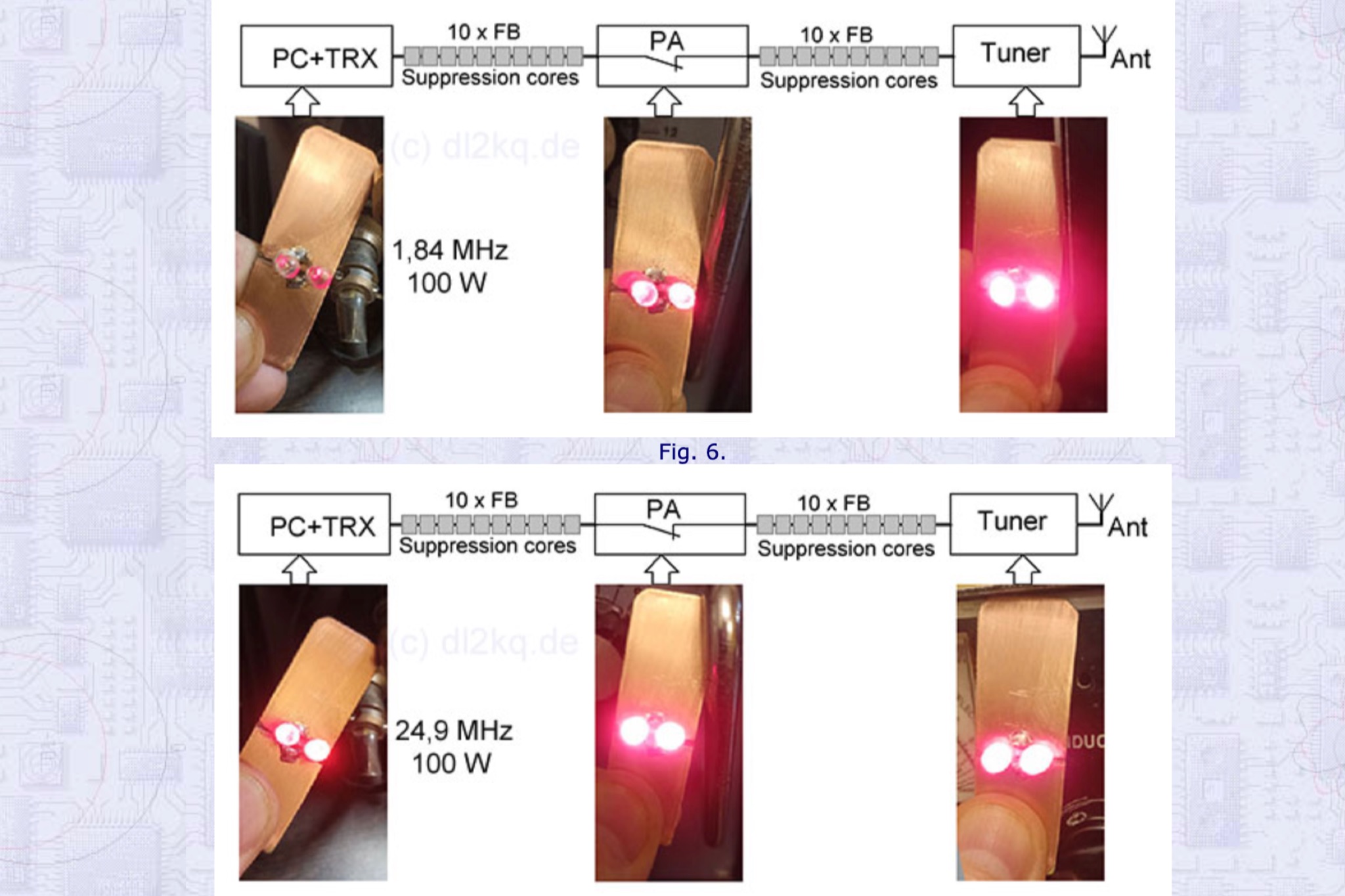 Detecting stray RF voltages on station grounds, chassis, and interconnecting cables is crucial for preventing program and hardware failures in the shack. This article details the construction and application of an LED RF V-probe, which offers significantly higher sensitivity compared to conventional neon lamp indicators. The probe leverages two specific properties of modern red LEDs: their ability to glow at microampere currents and their rectification capability at frequencies up to tens of megahertz. The design features a simple circuit with two LEDs, allowing for indication of both positive and negative RF voltage half-waves. The minimum detectable RF voltage is approximately 2 V, a substantial improvement over the 40-60 V threshold of neon bulbs. The resource illustrates the probe's physical construction on a PCB and provides a direct comparison demonstrating its superior sensitivity in detecting RF fields near a coil. Two operational modes are described: a non-contact mode for high RF voltages (above 15-20 V) and a direct-contact mode for measuring lower RF voltages, with a safety caution for the latter. Practical examples show the probe's use in analyzing RF voltage distribution across a radio station setup at 1.84 MHz and 24.9 MHz, revealing insights into common-mode current issues and the effectiveness of mitigation strategies like adding radials.
 -
 The article explores the concepts of return loss, VSWR, and S11 within the context of microwave engineering, highlighting the confusion arising from their definitions. It clarifies that these parameters, while seemingly distinct, fundamentally describe the same phenomenon related to wave reflection and transmission in microwave circuits. The discussion emphasizes the historical context and mathematical relationships among these terms, revealing that their interpretation can vary significantly across different engineering disciplines. Ultimately, it advocates for a pragmatic approach to using these parameters based on familiarity rather than strict definitions.
 -
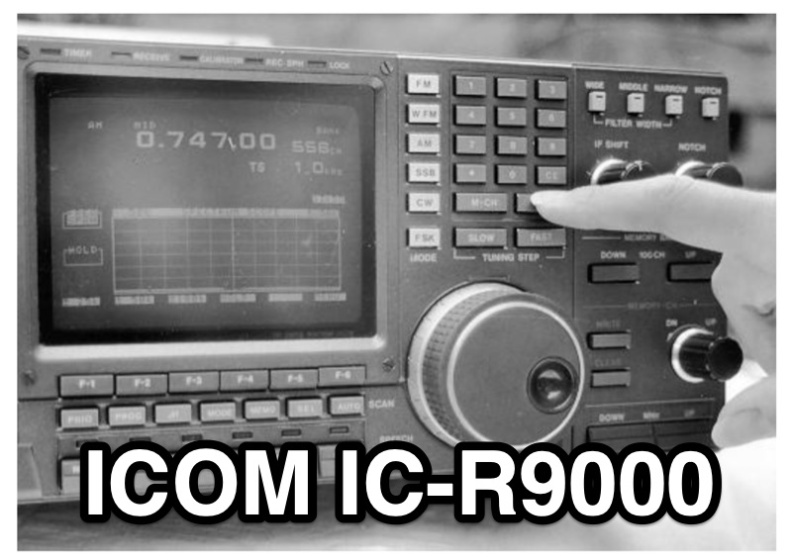 Assessing the ICOM IC-R9000 communications receiver, this review details its operational parameters and user experience for radio enthusiasts. Introduced in 1985, the IC-R9000 covers a broad frequency spectrum from 0.1 MHz to 1999.8 MHz, making it suitable for a wide array of listening activities from medium wave (MW) to VHF/UHF. Key performance metrics include a dynamic range of **102 dB** with the narrow SSB filter, crucial for discerning weak signals in crowded bands, and its substantial physical dimensions of 424 x 150 x 365 mm and 20 kg weight. The receiver's architecture supports various modes, though it notably lacks synchronous detection, a feature often desired for improved AM reception under fading conditions. It incorporates 1000 memory channels and robust scanning capabilities, facilitating efficient monitoring across its extensive frequency range. This analysis provides insights into the IC-R9000's capabilities and limitations, offering a historical perspective on a significant piece of amateur radio and shortwave listening hardware.
 -
 This excel workbook addresses the issue of power loss in transmission lines with complex characteristic impedance ZoZo​. It illustrates the discrepancy between actual loss (0.35 dB) and matched line loss (0.6 dB) using a simplified example, highlighting potential software tool limitations. The RF Feedline Power-Loss Calculator provides accurate end-to-end loss assessments for both microwave and RF applications. This tool is suitable for engineers and students and is compatible with Windows versions of Excel 2016 or later, though it is not compatible with Macintosh systems.
 -
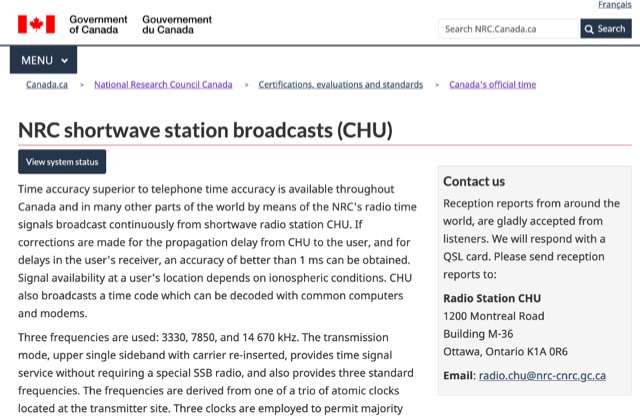 CHU is a time signal transmitter operated by the National Research Council in Canada. It broadcasts on various frequencies and is primarily used for time synchronization in North America.
 -
 AM radio listening excels at night due to sky-wave propagation, where signals travel farther by reflecting off the ionosphere’s F1 and F2 regions. Daytime ground wave propagation falters as solar radiation ionizes the D region, absorbing signals. At night, reduced ionization allows recombination, letting waves reach hundreds of miles. This enables tuning into distant stations, like KGO in San Francisco from Northern California. Enhanced by tools like the CCRadio-2E, sky-wave propagation turns AM listening into an exciting nocturnal adventure.
 -
 This project documents the construction of a coaxial 50 MHz notch filter to eliminate inter-band interference between 50 and 70 MHz transceivers. Using RG-213 coax and based on quarter-wave stubs, the filter achieved a 44 dB attenuation at 50.060 MHz while maintaining low insertion loss on 70 MHz. A dual-stub design broadened the notch response and minimized attenuation on 70 MHz to 0.2 dB. Fine-tuned using an FA-NWT network tester and Elecraft XG3 signal source, the filter effectively resolved interference for seamless dual-band operation.
 -
 A guide to constructing a simple quarter-wave ground plane antenna, detailing design principles and providing dimensions for VHF/UHF bands
 -
 KISS703 is a 703 Hz narrowband digital mode for amateur radio, designed for simple, low-power operation without computers. A 500 Hz pilot tone ensures frequency alignment, replaced by unique tones for 37 symbols (letters, numbers, space). Built from common discrete components, it draws about 40 mA at 12 V, ideal for SOTA/IOTA use. The receiver uses amplification, wave shaping, and a pulse-counting frequency meter for manual decoding via a calibrated meter. Transmitter and receiver calibration involves marking meter positions for each tone, enabling fully self-contained messaging with minimal hardware in portable or fixed operations.
 -
 This comprehensive article dispels common misconceptions about Standing Wave Ratio (SWR) in amateur radio. The author explains that SWR is not an antenna property but a measure of the entire antenna system, representing the mismatch between transmission line and load impedance. Contrary to popular belief, modest SWR values (under 3:1) typically cause minimal power loss in HF applications. The article demonstrates mathematically why obsession with achieving 1:1 SWR is often unnecessary, explains when SWR matters more (QRO, QRP, VHF/UHF), and explores effective matching techniques including proper ATU placement and quarter-wavelength transformers.
 -
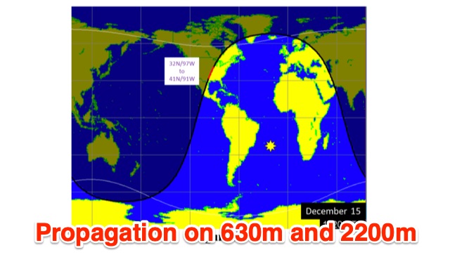 This is a theoretical look at propagation on 630-Meters and 2200-Meters using ray tracing software. It expands on the brief discussion in the ARRL Handbooks. The Earth's magnetic field affects 630-Meter and 2200-Meter band propagation. Lower ionization reduces absorption, aiding low-frequency propagation. Differences exist between bands, limited daytime sky-wave propagation. Sunrise/sunset show promise, yet mechanisms are unclear. Ducting possible at night in specific conditions. Negative ions enhance propagation. Inefficient antennas and high man-made noise are anticipated. Groundwave propagation is significant on 2200-Meters.
 -
 The Zeppelin antenna, a J-type design, is presented as a two-band HF dipole, offering independent operation on harmonically related frequencies. This resource details its electrical configuration, comprising a half-wave radiator end-fed by a quarter-wave matching section, and explores its historical evolution from early Zeppelin airship applications to modern amateur radio use. The article specifically examines how a Zepp antenna tuned to 28.4 MHz (10 meters) exhibits a harmonic relationship with 15.4 MHz (20 meters), noting a frequency ratio of approximately 1.84:1, which deviates from a perfect 2:1 due to factors like elevation, wire separation, velocity factor, and end-effect. Antenna modeling results, including SWR sweeps at 28.4 MHz (1.1 SWR) and 15.4 MHz (1.6 SWR), are provided through Graph 1 and Graph 2, illustrating the antenna's performance across these bands. Current distribution patterns for both the 28.4 MHz (second harmonic) and 15.4 MHz (first harmonic) operations are visually represented in Figure 2 and Figure 3, respectively. The author also includes a 4NEC2 model's "Symbol Conversion file" definitions and calculated #14 wire dimensions for achieving resonance at 28.4 MHz, with the antenna positioned at a height of 33 feet. The discussion further highlights the antenna's versatility, suggesting its potential as a single-band, center-fed, 15.4 MHz half-wave folded end dipole when fed at a specific low current point. This analysis provides practical insights into constructing and optimizing a multi-band Zepp antenna for HF operations, emphasizing its unique harmonic characteristics and physical compactness.
 -
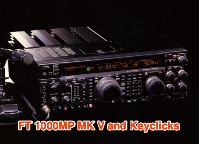 YaesuFT1000MK V stands out with improved close-spaced SSB transmit performance, reversing a trend seen in other modern radios. Featuring a class-A mode, it offers clean HV finals when kept out of ALC. However, two significant flaws persist: the noise blanker causes receiver IM distortion, and the transmitter lacks wave-shaping on CW, resulting in pronounced keyclicks. Preliminary tests reveal strong keyclicks +1kHz and -1kHz, prompting a combined modification to address both issues.
 -
 MyWaveRecorder is a lightweight utility designed to capture and save any audio played on your computer. Whether it’s sounds generated by programs like CW_PLAYER, WX_PLAYER, MyWaveRecorder itself, your microphone, your sound card, or even streaming audio from the internet, this tool records them all with a single click.
 -
 Operating amateur radio satellites presents unique challenges, particularly concerning antenna design and signal propagation. Juan Antonio Fernández Montaña, EA4CYQ, recounts his three-year journey into satellite communication, starting with initial guidance from EB4DKA. His early experiments involved a portable 1/4 wave VHF antenna with four 1/4 wave ground planes, designed for hand-held use to adjust polarity. This setup, paired with an FT-3000M transceiver, allowed full-duplex operation on **VHF** transmit and **UHF** receive, proving effective for early contacts on satellites like AO27, UO14, and SO35. EA4CYQ's experience highlights the critical role of coaxial cable loss and antenna polarization. After encountering significant signal degradation with longer RG213 runs, he experimented with a 1/2 inch commercial cable, noting improved reception but persistent fading due to varying satellite polarities. This led to the construction of an **Eggbeater II** antenna, an omnidirectional UHF design offering horizontal polarization at the horizon and circular right polarization at higher elevation angles. Subsequent modifications resulted in the directional **TPM2** antenna, which provided sufficient gain for LEO satellites with a wide 30-degree lobe, enabling consistent contacts from his home station. The article concludes with practical insights on the performance of the Eggbeater II for both UHF and VHF, and the TPM2 for UHF, emphasizing their utility for portable and fixed operations. EA4CYQ's journey underscores the iterative process of antenna development and the importance of adapting designs to overcome real-world propagation challenges in satellite communications.
 -
 A 5/8-wavelength vertical antenna for 2-meter FM operation is detailed, focusing on eliminating loading coils by utilizing a series inductor to cancel capacitive reactance at the feed point, thereby presenting a 50-ohm impedance match. The design illustrates three basic configurations, including a method employing a short-circuited coaxial stub for inductance, as implemented by K4LPQ. An alternative design is presented where the center conductor of the stub is extended one-quarter wavelength, creating a signal-frequency short and allowing for an insulated wire stub to develop the required series inductance. The article provides electrical theory and mechanical considerations for building the antenna, emphasizing the adjustment of stub length for proper impedance matching. This technical documentation is intended for amateur radio operators interested in homebrewing VHF antennas, offering practical insights into impedance matching techniques for vertical radiators.
 -
 The article discusses the construction of a UHF band-stop stub filter to protect an APRS receiver from potential damage during a balloon launch. The author, who communicates using a 441 MHz transmitter, needed to ensure that the RTL-SDR dongle receiving at 144 MHz wouldn't be damaged by the transmissions. The solution involved creating a quarter-wavelength open stub filter using coaxial cable, which attenuates the 441 MHz signal while allowing the 144 MHz signal to pass through. The filter's design is based on the principles of constructive and destructive interference, with careful measurement and trimming to achieve the desired frequency response. The final filter provided 34.8 dB of insertion loss at 441 MHz and minimal loss at 144 MHz, effectively protecting the receiver.
 -
 Demonstrates a specific impedance matching technique for resistive loads ranging from 22.2 to 45 ohms, connecting them to a 50-ohm transmission line. The method employs series sections of 50-ohm and 75-ohm coaxial cables, with graphical data illustrating the required cable lengths (L1 and L2) in wavelengths for a perfect match. This approach is particularly useful for feeding **vertical** and **Yagi antennas**. The resource provides a practical example of matching a 25-ohm Yagi antenna at 50.150 MHz, specifying the use of RG-58C/U (50 ohms) and RG-59B/U (75 ohms) cables, both with a 66% velocity factor. It calculates the precise physical lengths in centimeters and inches for the required cable sections. Additionally, the document briefly discusses integrating a balun at the load end, suggesting methods such as coiling a cable section or utilizing ferrite beads to create a W2DU-type balun. The presented methodology offers a clear, data-driven solution for common antenna impedance challenges.
 -
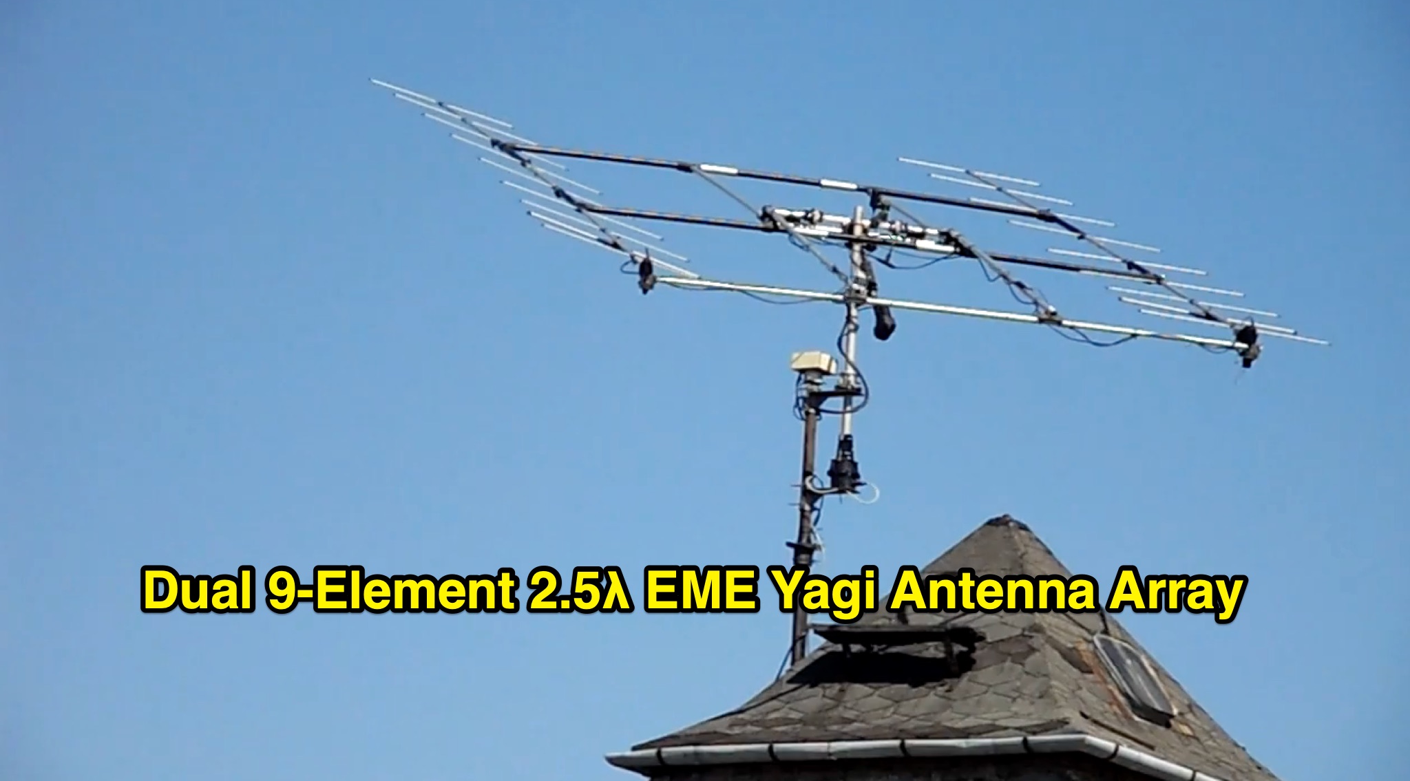 This project describes a high-performance EME antenna array consisting of two home-designed 9-element Yagis, each about 2.5 wavelengths long, combined into a 25-ohm system and matched to 100 ohms using 9/4λ sections of 50-ohm coax. The array supports rotatable polarity from 0° to 180°, allowing both horizontal and vertical polarization to optimize moonbounce performance under varying conditions. Despite operating for years without a balun—something another designer called “disastrousâ€â€”the system has delivered strong results, including copying very weak DX such as VK3KH at about -25 dB with only 120 W (around 2 kW ERP). The builder continues to refine the mechanics, having installed new gear motors and an upgraded follow-up control system in 2011.
 -
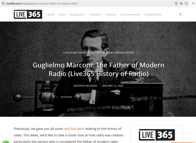 Tracing the foundational work of Guglielmo Marconi, this article details his early laboratory experiments in 1895, where he successfully transmitted wireless signals over 1.5 miles. It highlights his 1896 patent for a wireless telegraphy system in England and subsequent demonstrations, including signal transmissions up to 6.4 km (4 miles) on Salisbury Plain and nearly 14.5 km (9 miles) across the Bristol Channel. Marconi's work built upon the mathematical theories of _James Clerk Maxwell_ and the experimental results of _Heinrich Hertz_, proving the practical feasibility of radio communication. The resource further chronicles the formation of The Wireless Telegraph & Signal Company Limited in 1897 and Marconi's relentless efforts to popularize radiotelegraphy. A significant milestone was the 1901 transatlantic reception of the Morse code letter "S" from Poldhu, Cornwall, at St. John's, Newfoundland, using a kite-supported wire antenna, defying contemporary mathematical predictions about Earth's curvature limiting range. This achievement underscored the global potential of radio. The article also touches upon Marconi's later discoveries, such as the "daytime effect" concerning atmospheric reflection of radio waves, and his 1902 patent for a magnetic detector, which became a standard wireless receiver. His contributions earned him a Nobel Prize in 1909.
 -
 This page by Arctic Peak provides a detailed explanation on how to use quarter-wave transmission lines as impedance transformers in ham radio antenna work. It explains how to match impedance values by connecting them with a λ/4 transmission line. The page also offers guidance on constructing your own transmission lines with specific impedance requirements, along with a calculator to determine the quarter wave length based on velocity factor and frequency. Useful for hams looking to optimize antenna performance and match transmission line impedance effectively.
 -
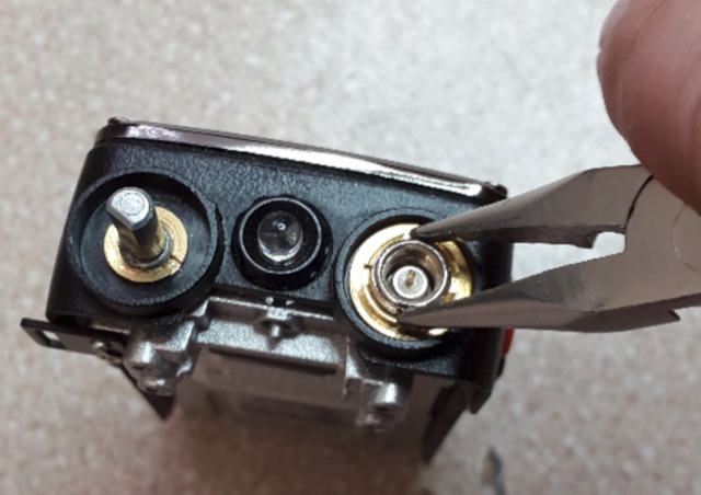 Fix the no-mic problem with the Baofeng UV5R+. It may happen the carrier wave is there, but there is no modulation.
 -
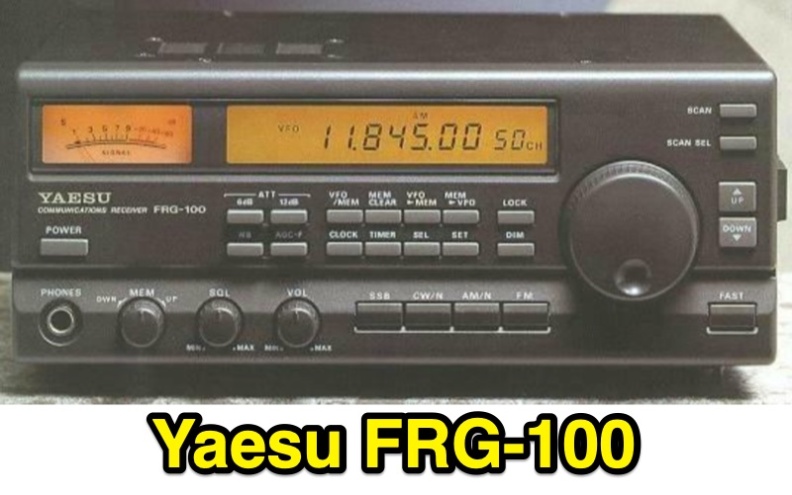 The **Yaesu FRG-100** shortwave receiver, introduced in 1992, operates across a frequency range of 50 kHz to 30 MHz, accommodating AM, LSB, USB, and CW modes, with an optional narrow-band FM capability. Its physical dimensions are 238 x 93 x 243 mm, with a weight of 3 kg, making it suitable for both portable and fixed station deployments. Power options include standard mains voltage or 12VDC, providing operational flexibility for diverse listening environments. The front panel integrates a manual tuning knob, an analogue signal strength meter, and an LCD display that provides critical information such as frequency, operating mode, memory channel, and time. Users can configure various operational parameters, including tuning steps and bandwidth filters, to optimize reception for specific signals. This review highlights the FRG-100's straightforward interface and its utility for shortwave listening enthusiasts. The design emphasizes user-friendly adjustments for settings, which contributes to its appeal among those interested in general coverage reception.
 -
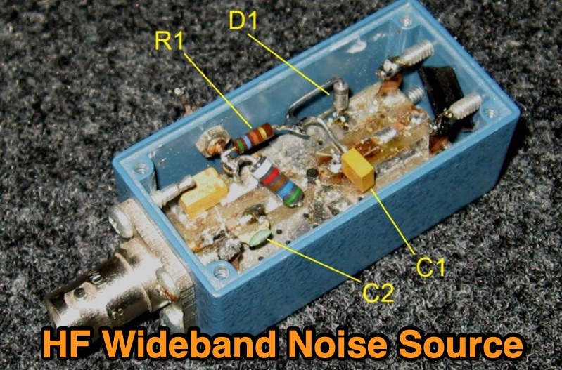 Details the construction of a **wideband noise source** for HF filter alignment, specifically targeting transceivers such as the Elecraft K2. The design modifies a Down East Microwave (DEMI) MMIC amplifier board, part number MMICPCB, by integrating a 1N4735A zener diode, 560-ohm resistors, and 4.7 nF, 10 nF, and 22 µF capacitors. This modification enables the board, originally configured for a MAR-6 MMIC (with MAR-1 as an alternative), to generate noise suitable for procedures like the K2's "CAL FIL" function. The resource provides a **schematic** and a comprehensive bill of materials, including specific component values for replication. It outlines the practical steps involved, such as removing the input connector and integrating the new components into the existing MMIC amplifier board layout. The output is optimized for wideband HF applications, ensuring compatibility with various filter alignment tasks. This project focuses on practical implementation, demonstrating how to repurpose readily available components for a critical test instrument. It offers a cost-effective alternative to commercial noise sources, leveraging existing amateur radio hardware for enhanced station maintenance and performance.
 -
 Constructing a **J-Pole antenna** from 450 Ohm ladder line for 2-meter (144 MHz) and 70-centimeter (440 MHz) operation involves specific calculations and assembly steps. The design, based on an earlier KD6GLF concept using 300 Ohm twinlead, features a ¾ wavelength radiator and a ¼ wavelength matching stub, functioning as an end-fed half-wave antenna without requiring ground radials. It offers a gain of 2.4 dB over isotropic. The resource provides the formulas for determining the lengths of the ¾ wave radiator and ¼ wave stub, incorporating a velocity factor of 91% for 450 Ohm ladder line. For 146 MHz, the radiator measures 55 3/16 inches and the stub 18 3/8 inches. Construction details include cutting a 57¾-inch piece of ladder line, stripping 4 inches from one end, and attaching a 24-inch section of RG58 or RG8X coax with a 3-5 turn RF choke. SWR adjustment is achieved by sliding a shorting bar or by incrementally trimming the elements at a 1:3 ratio (stub to radiator). The goal is a 1:1.1 SWR at 146 MHz, which typically yields 1:1.2 at 446 MHz. The article also discusses power handling, noting that while 10-15 watts is fine, 50 watts may increase SWR to 1:2.1, and advises keeping the antenna away from other objects to prevent coupling and SWR degradation.
 -
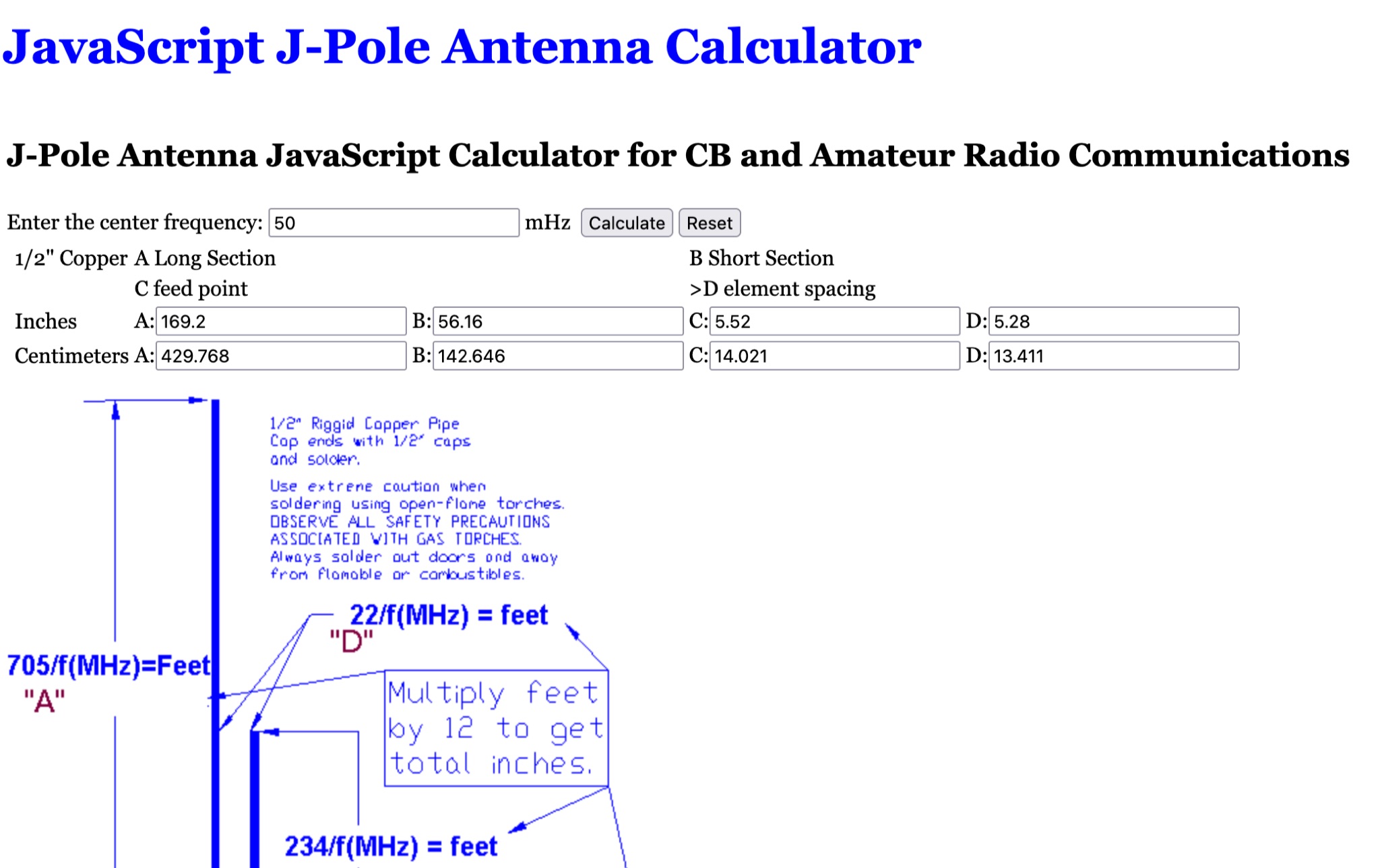 This page provides a detailed guide on the J-pole antenna, an end-fed half-wave antenna matched to the feedline by a quarter-wave transmission line stub. It covers the characteristics, construction materials, feeding options, and mounting considerations for optimal performance. The information is useful for hams or amateur radio operators looking to build and set up a J-pole antenna for improved transmission and reception.
 -
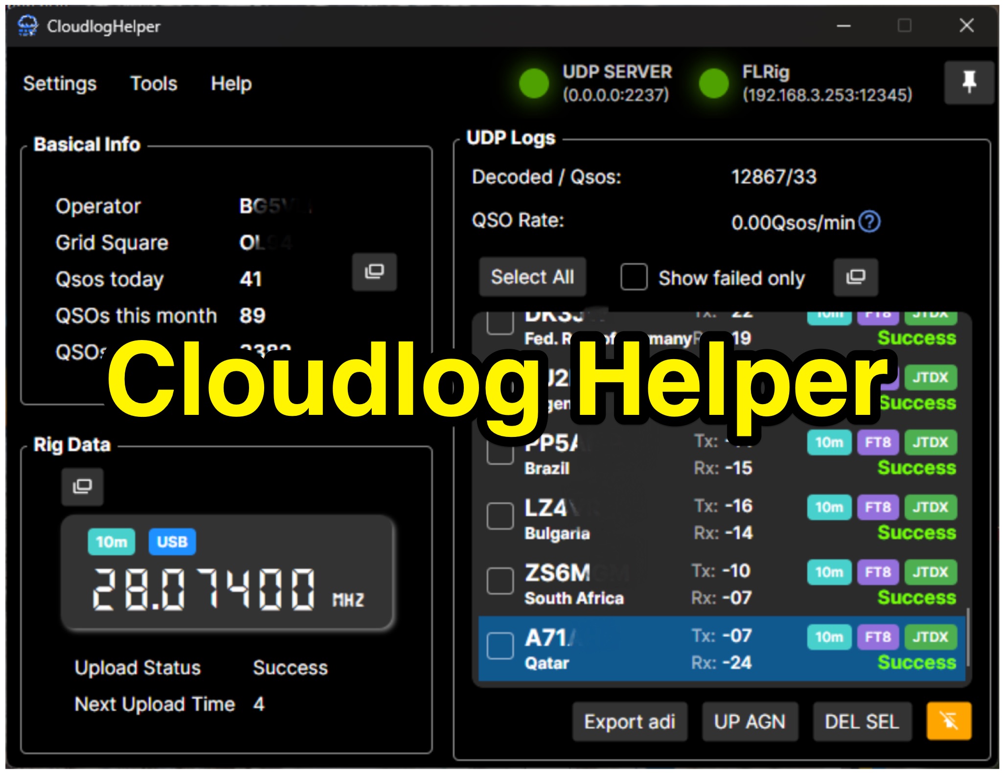 Cloudlog Helper addresses the need for streamlined, automated logging of amateur radio contacts, particularly for operators utilizing digital modes like FT8 or those with limited system resources. This utility syncs real-time rig data and QSO information to various logging platforms, including _Cloudlog_ and Wavelog, supporting mainstream transceivers. It integrates seamlessly with popular digital mode software such as JTDX and WSJT-X, ensuring that contact details are captured and uploaded without manual intervention. Operators can compile the software themselves and configure essential settings, including their Maidenhead locator, Cloudlog server address, API key, and station ID. The application's design prioritizes efficiency and portability, making it a practical solution for hams who prefer automated logging processes. While an unofficial community project, Cloudlog Helper provides a robust framework for automating the often-tedious task of logging, supporting multiple logging services beyond its primary integration. It offers a direct method for hams to maintain accurate and up-to-date logbooks with minimal effort, potentially improving their DXCC or other award tracking by ensuring no QSO is missed.
 -
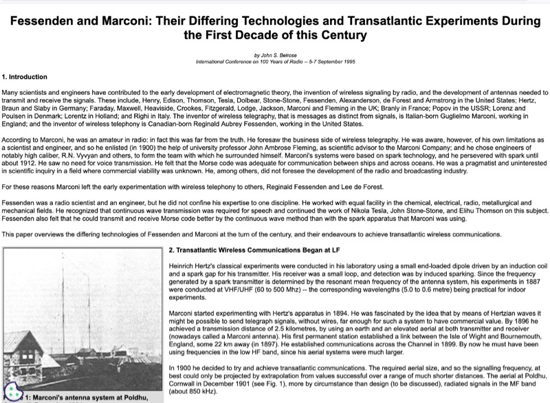 Early 20th-century transatlantic wireless communication efforts involved distinct technical approaches by Reginald Fessenden and Guglielmo Marconi. Marconi's systems, operational until approximately 1912, primarily utilized _spark technology_ for wireless telegraphy, facilitating Morse code communication between ships and across oceans. His Poldhu station in December 1901 radiated signals in the MF band around 850 kHz, later evolving to 272 kHz in October 1902, and eventually 45 kHz by late 1907 with increasingly larger antenna structures like the pyramidal monopole and capacitive top-loaded arrays. Fessenden, conversely, focused on _continuous wave transmission_ for wireless telephony, recognizing its necessity for speech. His transatlantic experiments in 1906 employed synchronous rotary-spark-gap transmitters and 420-foot umbrella top-loaded antennas at Brant Rock, MA, and Machrihanish, Scotland, tuned to approximately 80 kHz. Fessenden later utilized the _Alexanderson HF alternator_ at 75 kHz by late 1906 for pure CW transmission, integrating a carbon microphone for amplitude modulation. Receiver technology also differed, with Marconi initially relying on untuned coherer-type detectors, later developing the magnetic detector in 1902, while Fessenden's CW approach necessitated more advanced detection methods.
 -
 The W6PQL 23cm Beacon Project describes a **1296 MHz** beacon designed for microwave propagation studies and equipment testing, capable of 30 watts output. It utilizes a PIC 16F628A microcontroller to generate CW and FSK keying for a crystal oscillator, followed by a series of frequency doublers and triplers to reach the target frequency. The final power amplification stage employs a Mitsubishi M57762 module, providing a robust 10-watt RF output. The design emphasizes stability and reliability for continuous operation, with the microcontroller code, written in assembly, provided for customization of the beacon's callsign and message. Originally located in CM97am and aimed at 140 true, the beacon used four 4-foot Yagis stacked vertically for a total ERP of 3kW. The article includes schematics, parts lists, and construction notes to guide builders, along with antenna pattern measurements. Although the beacon itself is no longer in service as of August 2010, the detailed documentation remains a valuable reference for amateur radio operators interested in building similar **microwave** projects or understanding beacon operation.
 -
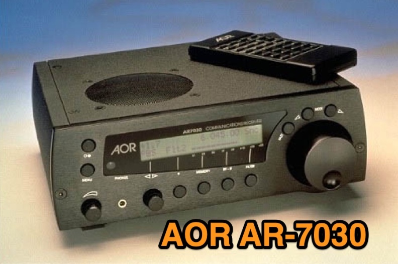 Examines the AOR AR-7030 communications receiver, detailing its technical specifications and operational characteristics. The resource describes its compact design, CNC machined aluminum cabinet, and a frequency range spanning 0-32 MHz. Key features include a ceramic metal cased 4 kHz AM filter, with typical bandwidths of 2.2 kHz, 4.0 kHz, 5.3 kHz, and 9.5 kHz, alongside 400 memory channels and multi-timer functionality. It emphasizes the receiver's high-quality components and a design philosophy focused on reliable performance without superfluous features, making it a dedicated tool for serious listeners. The review assesses the AR-7030's performance within its price class, particularly for **medium wave** and **shortwave** reception. It provides insights into how the receiver's design choices, such as its robust construction and specific filter options, translate into practical listening experiences. The analysis highlights its suitability for users prioritizing signal clarity and operational stability over extensive, complex features, offering a clear perspective on its utility for dedicated DXers and broadcast listeners.
 -
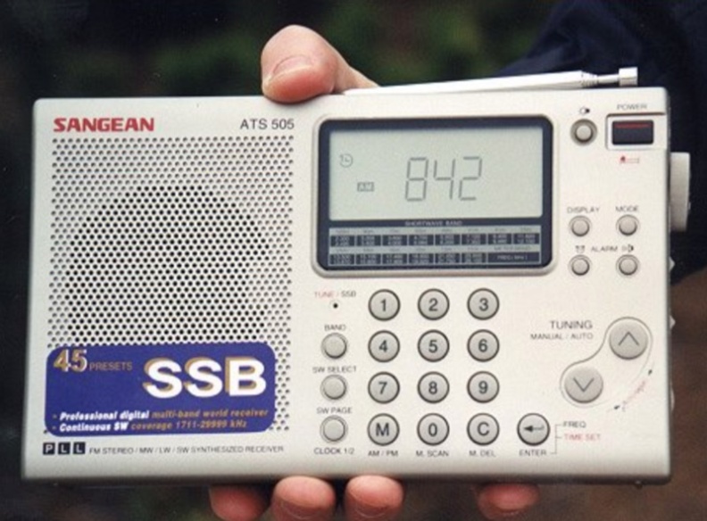 Examines the Sangean ATS-505 portable receiver, a unit introduced in March 2000, providing an in-depth analysis of its capabilities. The review details critical specifications such as its 6 Volt DC power requirement, utilizing 4 AA batteries, and its physical dimensions of 128 x 214 x 39 mm, weighing 840 g without power cells. Frequency coverage spans **LW** from 153-279 kHz, **MW** from 520-1710 kHz, **SW** from 1711-29999 kHz, and FM from 87.5-108 MHz, making it a versatile listener for various broadcast types. Key features highlighted include a backlit display for low-light operation, 45 memory presets for quick access to favorite stations, and the inclusion of Single Sideband (SSB) mode, which is crucial for serious shortwave listening and utility monitoring. The review also draws technical comparisons with other Sangean models, specifically the ATS-404 and ATS-909, pointing out differences in band coverage and operational features. This independent assessment offers practical insights into the ATS-505's performance, helping enthusiasts understand its place within the portable receiver market.
 -
 The Alfa Alfa (AA) DX Group, established on March 1, 1974, in the Netherlands, is presented as the pioneering Dutch 27mc DX group. It details the group's historical significance, particularly its revolutionary use of the '000' club callsign (19AA000) which influenced international 11-meter group callsign structures. The resource outlines the group's re-establishment in 2024, inviting new active CB operators and _Short Wave Listeners_ (SWL) to join its ranks, emphasizing a free worldwide membership model. Membership requirements are specified, focusing on active participation with an assigned AA callsign. The group provides QSL card management services, with options for direct QSL requests requiring **3 USD** and a Self-Addressed Envelope, or **4 USD** via PayPal for expenses. It also mentions upcoming initiatives like an _AA DX Contest_ and an award program, with sections for certificates and plaques currently under construction. The site also lists useful CB resources, including an 11M DX Cluster and an 11M Callsign Database, and provides contact information for the founder, 19AA001 Mr. Theo, and the Worldwide QSL Manager, 178AA001 Mr. Emil, based in Bulgaria.
 -
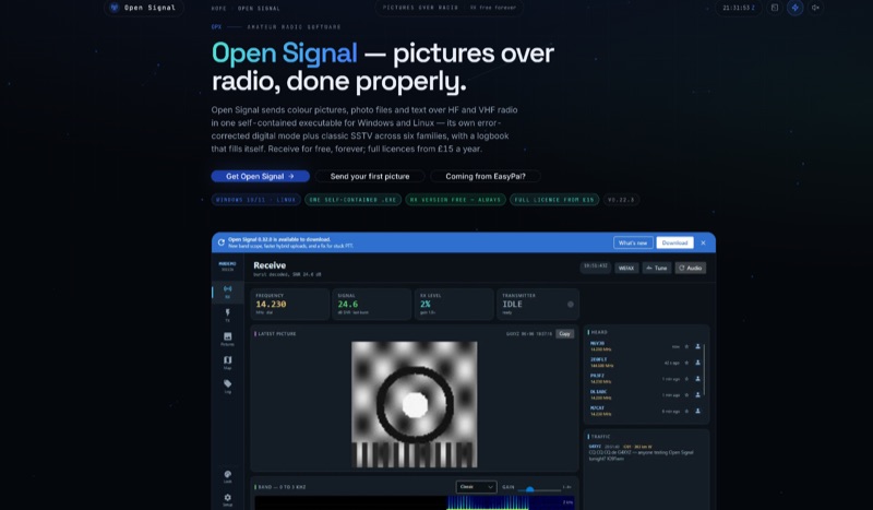 Open Signal, a software application for Windows 10/11 and 64-bit Linux, facilitates the transmission of color pictures, photo files, and text over HF and VHF amateur radio bands. It integrates its own error-corrected OFDM digital picture mode, delivering pixel-exact images in under a minute, with classic analog SSTV across six families: Martin, Scottie, Robot, Wraase, PD, and MMSSTV's MP/MR, featuring automatic VIS mode detection on receive. The application offers four distinct sending methods, including byte-exact JPEG transfer, a hybrid mode utilizing internet for full quality with a short RF link, and its proprietary digital waveform. This self-contained executable eliminates the need for external software like FLDIGI, Hamlib, or virtual audio cables, simplifying setup. It includes a self-filling logbook that integrates with Wavelog/Cloudlog, eQSL, and provides UDP ADIF broadcast. Built-in spotting features include PSK Reporter, DX cluster announcements, and APRS-IS position beacons. The receive-only version is permanently free, while a full license, enabling transmit capabilities and access to the live network, is available for an annual or lifetime fee. The software is actively maintained, unlike EasyPal, which has not seen updates since 2014.
 -
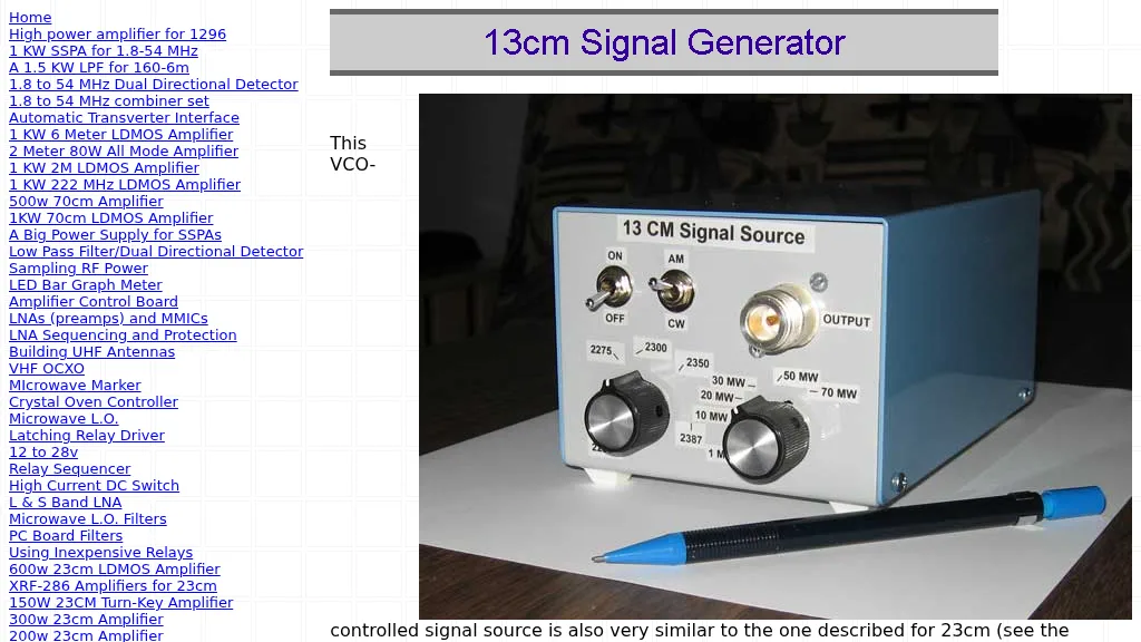 This online construction guide details the assembly of a signal generator specifically for the **13cm band** (2.4 GHz). The curriculum focuses on the integration of a Voltage Controlled Oscillator (VCO), specifically the ROS-2400, to produce a stable RF signal. The resource outlines the necessary components for frequency generation and output, including the use of a Mini-Circuits MMIC amplifier for signal conditioning. The construction protocol involves configuring the ROS-2400 VCO to operate within the 2.3 GHz to 2.45 GHz range, ensuring frequency coverage for amateur radio _microwave experimentation_. The guide specifies the output power level, approximately 70mW, directly from the MMIC stage, indicating its application as a low-power instrumentation source rather than a transmit-capable device. This project provides a practical example of constructing a dedicated test instrument for microwave frequency measurements and system alignment on the **13cm band**. DXZone Focus: Construction Guide | 13cm Signal Generator | VCO Integration | Microwave Experimentation
 -
 Define the SWL contest 2026 as an event for monitoring a variety of languages on _medium wave_ (MW) and _shortwave_ (SW) AM radio stations. Participants can utilize either traditional radio receivers or _WEB SDR_ platforms to log their findings. The contest encourages the use of both analog and digital methods to maximize the diversity of languages captured. The contest rules specify that entries must include detailed logs of the stations received, including frequency, time, and language identified. Logs should be submitted in a standardized format to ensure consistency and accuracy in judging. The use of WEB SDR is particularly highlighted for its ability to access distant stations that may not be reachable with local equipment. The contest is open to all SWL enthusiasts worldwide, with a focus on European WEB SDR access. The event aims to foster a deeper understanding of global broadcasting patterns and linguistic diversity. Participants are encouraged to explore various bands within the MW and SW spectrum, enhancing their skills in signal identification and language recognition. The contest offers a unique opportunity to engage with the global SWL community and share insights into the art of listening.
 -
 AA DX Group was founded in March 1, 1974 in The Netherlands. Our members was more than 10000 from all over the World. Because during the years many of our members became "Silent Keys" or they are not active on the air anymore, we deceide to make new fresh group and to delete all old database. So, we are the new - old Alfa Alfa DX Group and you are welcome to be our member. We make avaiable all Alfa Alfa numbers for new and active CB members and SWL ( Shrot Wave Listeners ). Alfa Alfa World Wide DX Radio group is looking or ACTIVE CB Operators and SWL stations ! The New AADX team in in 2024 Main base in 178AA000 178AADX000 in Belgaria
 -
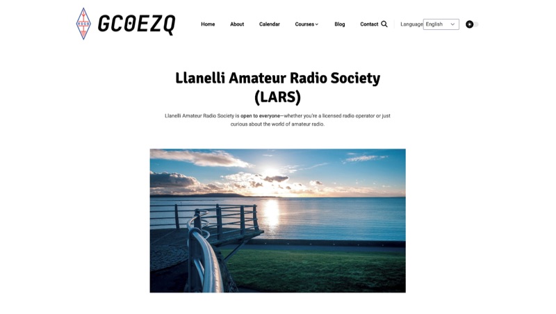 The Llanelli Amateur Radio Society (LARS) website details the club's offerings for both licensed operators and those new to amateur radio, including shortwave listeners and individuals pursuing Foundation, Intermediate, or Full licenses. It highlights opportunities to learn radio techniques, explore digital modes such as C4FM, D-Star, DMR, and FreeDV, and participate in contests and social events. The club aims to foster a supportive environment for experimentation and knowledge sharing among its members. Member testimonials illustrate practical applications, such as a new licensee making a 1000km contact via a repeater after being inspired by space exploration, and another quickly passing the RSGB Foundation exam. The site also features accounts of members progressing to Intermediate and Full licenses, with one Full license holder continuing to learn new modes like CW and digital, and engaging in activities like Parks on the Air (POTA).