Search results
Query: 20 meter
Links: 529 | Categories: 6
-
 A rotary trapped-dipole for 17 and 20 meters, as described by IZ7ATH, presents a practical solution for multi-band HF operation. The author, Talino, recounts his experience building this antenna for IK7ZCQ, detailing the evolution from an initial concept involving a grounded-driven element and gamma-match to a direct-fed, non-grounded design. His pragmatic approach, adapting available materials, is evident throughout the construction narrative, particularly with the use of eight tapered aluminum pipes for the driven element. Construction specifics include precise measurements for the aluminum tubing, with diameters ranging from 30 mm down to 16 mm, and a critical note on reducing tip thickness for weight optimization. The _traps_, initially a concern, are fabricated using 8 turns of RG58 coax on a 27 mm support, tuned to resonate at 18.1 MHz using a dip-meter. Talino emphasizes sealing the traps with RF glue and PVC tape to prevent water ingress, a crucial step for longevity. Field test results, conducted on a 10-meter pole in a clear garden environment, showed an SWR of 1.2:1 on 17 meters and 1.5:1 at 14.200 MHz. While SWR varied slightly when installed at Mario's QTH due to nearby objects, the antenna's performance remained commendable. The final half-dipole length is 46 cm for the 18 MHz tips, and the total weight is under 6 kg, with potential for further reduction.
 -
 20 meter wire j-pole for 14.2 MHz, a vertical, end-fed half wave antenna by N1LO
 -
 A homebrew project for a 2 meter 4 element yagi beam antenna by 2E0HTS
 -
 This project describes an ARDUINO based automatic antenna tuner, for an end-fed half wave (EFHW) antenna, working on 20 & 40 meter bands
 -
 A 3 element yagi beam for 40 meters band
 -
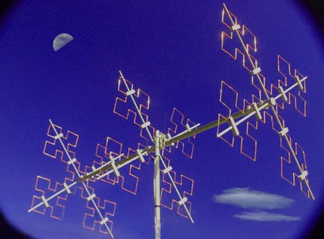 A Quad Fractal Antenna for 20 meters band by F3DD
 -

-
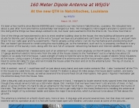 Pictures of the 160 meters dipole antenna at W5JGV
 -
 A double dipole for the 20 and 15 meters band in french
 -
-
 This antenna project came out very nice. It's a rugged homebrew multi-band trap vertical antenna that works the 10, 15, and 20 meter amateur radio bands. The antenna can be mounted on the ground or on a mast. Mounted on the ground the antenna has a low take off angle for working DX. If mounted on a mast the antenna will acheive both a low angle as well as another radiation lobe that has a much higher take off angle.
 -
 This very large moxon antenna resonate on 80 40 and 10 meters, has been used for CQWW 2006 by a YU team project
 -
 A site devoted to Amateur Radio Homebrewing, CW-decoder, CW QRP Transceiver for the 40 & 20 meters band, CMOS reader
 -
 10 to 20 meters band log-periodic antenna project with SWR Plots, boom lenght and element spacing.
 -
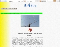 IK4DCS experience on maintaining a multiband delta loop antenna for 10/12/20 meters.
 -
 MQ-1 four band HF beams 20,15,10,6 meters MQ-2 six band HF beams 20,17,15,12,10,6 meters, beam antennas and Hybrid Quad antennas
 -
 A Moxon rectangle antenna projects for the 6 10 15 17 and 20 meter band but include drawings, plans, statistics and homebrewing statistics.
 -
 End-Fed Half-Wave Antennas (EFHWAs) are analyzed for their utility in portable QRP operations, emphasizing their simplicity, efficiency, and predictable radiation patterns compared to other portable antenna types. The discussion contrasts EFHWAs with vertical antennas, random length wires, and center-fed dipoles, highlighting the common pitfalls of each, such as ground system dependency for verticals and feedline issues for dipoles. The article details the electrical half-wavelength calculation using the formula L (Ft) = 468/F(MHz) and explains how EFHWAs can be resonant on harmonic frequencies, enabling multiband operation. Various deployment configurations are presented, including the inverted L, inverted Vee, sloping wire, and vertical setups, each with specific advantages for radiation angle and polarization. For instance, a vertical EFHWA offers a low angle of radiation suitable for DX contacts without requiring an extensive ground system. The resource also addresses the counterpoise requirements, suggesting a quarter-wavelength wire or connection to a metallic structure for decoupling. A schematic diagram for a simple parallel-tuned circuit tuner, based on the _Rainbow Bridge/Tuner_ design, is provided, detailing component values for 30 and 40 meters, including a 6 microhenry toroidal inductor and a 20-100 picofarad mica compression capacitor. The tuner's adjustment process for SWR matching is also outlined.
 -
 Details a practical QRP wattmeter construction, leveraging a simplified SWR meter design by JA6HIC. The project focuses on a forward-only power measurement circuit, providing a functional instrument for RF power levels from milliwatts up to 5 watts. It maintains a 50-ohm input and output impedance, suitable for typical QRP transceivers and antenna systems. The resource includes the schematic for the "VSW" (Very Simple Wattmeter) and outlines a six-step alignment procedure. This calibration process involves using a known RF source up to 5W, setting full-scale deflection, and marking power increments. It also addresses minimizing frequency effects on readings with a 100pF trimmer capacitor, noting that measurement error is highest at the lower end of the scale. Construction notes mention using a piece of RG-213 coaxial cable for the inductance and coupler, with the wattmeter assembled in early 2003. The author provides an example measurement showing 0.8W into a dummy load and 1W into a 3-element beam.
 -
-
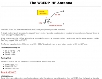 G3YCC article pn the W3EDP end-fed antenna for 80 to 20 meters bands
 -

-
 This PDF document, authored by KT4QW in October 2004, details the construction and modeling of a dual-band, horizontally polarized hanging rectangular loop antenna for **10 and 17 meters**. The design, adapted from *The ARRL Handbook*, utilizes _NEC4WIN95_ software for scaling and optimization, targeting a 50 ohm feedpoint impedance. The resource includes a bill of materials, step-by-step construction instructions, and a discussion of the antenna's radiation characteristics. It presents NEC-generated elevation and azimuth patterns, comparing the loop's performance to a half-wave horizontal dipole at the same height and frequency. The 17-meter element is centered at 18.140 MHz for low SWR across the phone band, while the 10-meter element is centered at 28.500 MHz. Construction involves 14-gauge stranded copper wire and Schedule 40 PVC spreaders, with the total wire length calculated by the formula: Length in feet = 1005/MHz. The feedpoint impedance can be adjusted by modifying the rectangular aspect ratio. The document specifies hoisting the antenna to at least a half-wave above ground for testing. It notes that a balun was tested and found to have no measurable effect on SWR or radiation characteristics. A 2-meter scale model is presented to illustrate the physical design, and a "rotator" string is incorporated for directional adjustment up to 90 degrees.
 -
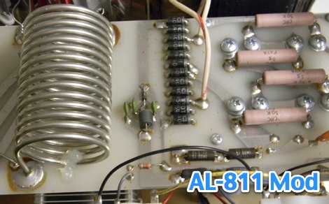 Pictures of the Ameritron AL-811 modification for 10 meter band extension by km5ps
 -
 The Buddipole website showcases a range of portable amateur radio antenna systems, including the **Buddipole**, Mini-Buddipole, Buddistick PRO, and BuddiHEX, designed for rapid deployment and multi-band operation from 40 meters to 2 meters. Each product page details specifications, operational modes (dipole or vertical), and compatible accessories like tripods, masts, and baluns. The site also features portable DC power management systems such as the PowerMini 2 and PowerPlus, which include integrated battery chargers and solar controllers, catering to off-grid or field day setups. Instructional videos demonstrate antenna assembly, tuning, and deployment techniques for various configurations, including the VersaTee vertical and Mini-Buddipole. Customer testimonials and DXpedition highlights, such as operations from Montserrat (VP2M) and Dominica (J38), provide real-world examples of the equipment's performance in challenging environments. The company, established in 2001, emphasizes modularity, versatility, and efficiency in its product line, all manufactured in the USA. Shipping information, a 30-day return policy with no restocking fee, and contact details for their Heber City, Utah facility are clearly presented. The site serves as a direct sales portal, offering a comprehensive catalog of antennas, power solutions, and components for portable amateur radio enthusiasts.
 -
 Download a 6 meter moxon antenna, drawings, photos, plots by Allen Baker KG4JJH, (10 Mb!)
 -
 A simple to build Yagi 2 element antenna for 15 or 20 meters band by 9m2mso
 -
 Presents _DirLog_, a freeware logging application specifically developed for the 11-meter CB band, catering exclusively to members of the _Alfa Tango Group_. The software facilitates the recording and management of contacts, providing a dedicated tool for CB operators to maintain their station logs. Its development spans from 1997 to 2025, indicating a long-term commitment to its maintenance and evolution by its author, 1AT069 Enio. This specialized logbook offers features tailored for CB operations, allowing users to track their contacts within the 27 MHz band. While primarily focused on CB logging, its structure and functionality could be compared to amateur radio logging software in terms of data entry and retrieval. The exclusivity to Alfa Tango members suggests a community-specific utility, fostering organized record-keeping among its users.
 -
 An homebrew project for a 3 elements yagi monoband antenna for the 20 meters by 9M2MSO
 -
 A direct drive ring radiator antenna for the 40 meters band by W6WYQ QST article.
 -

-
 Doublet multiband antenna for 80 to 10 meters band by
 -
 A homebrew project for a multiband end-fed antenna made with a single FT140-43 and 50pf capacitor and 20 meters of wire.
 -
 The document details the optimization and construction of the _Maria Maluca_ antenna, a compact 6-band (20m-6m) directional beam. It presents a comparative analysis of shortwave antenna principles, highlighting the efficiency gains achieved by using an open feeder line and tuner as a resonant unit, contrasting this with the losses associated with traps or capacitive loads in multiband antennas. The resource specifically revisits an older South American 2-element design for 10, 15, and 20 meters, applying modern NEC-based software to develop a six-band version. Performance data is meticulously tabulated, showing impedance, free space gain, gain at 12m height, elevation angle, and front-to-back (F/B) ratio for each band from 20m through 6m. For instance, on 15m, the antenna achieves 5.1 dBd free space gain and 13.72 dB F/B ratio. The construction section provides practical guidance on element assembly using aluminum pipes and hose clamps, detailing the use of a heavy-duty glass fiber reinforced polyamide rod for electrical separation and bending strength. It also specifies the use of 450-ohm _Wireman_ line CQ 552 for the transmission line. The document includes diagrams for rod fixing, an air-wound balun, and a vertical elevation diagram for the 15m band, illustrating its DX qualification. It also discusses the antenna's suitability for portable and expedition operations, noting its compact transport dimensions (max 1.50m length, 12 lb weight) and quick assembly time (under 15 minutes). The author, Dipl.Ing. Helmut Oeller, DC6NY, is identified as a source for material kits.
 -

-
 The article "Exploring the World of 10 Meter Beacons" by Ken Reitz, KS4ZR, provides an in-depth look at 10-meter beacon operations, focusing on their utility for propagation analysis. It details FCC Rules part 97.203 governing beacon stations, including license requirements, power limits (under 100 watts), and the specified band segment of 28.200-28.300 MHz for U.S. operations. The content highlights the diversity in beacon construction, from converted CB radios to home-brew QRP transmitters, and discusses the robust operating conditions these 24/7 stations endure. The resource presents several case studies of active 10-meter beacon operators like Ron Anderson KA0PSE/B, Domenic Bianco KC9GNK/B, and Bill Hays WJ5O/B, detailing their equipment, antenna setups, and typical signal report volumes. It also introduces the NCDXF/IARU International Beacon Project, which features 18 synchronized beacons worldwide transmitting on 28.200 MHz at varying power levels (100W, 10W, 1W, 100mW) to facilitate propagation testing. The article also covers the PropNet Project utilizing PSK31 on 28.131 MHz and the 250 Synchronized Propagation Beacon Project on 28.250 MHz. Practical advice for monitoring includes using the RST reporting method, understanding the impact of the solar cycle on 10-meter propagation, and tips for setting up a personal beacon, such as frequency selection and power output considerations. The IY4M Guglielmo Marconi Memorial Beacon Robot on 28.195 MHz is also mentioned for its automatic QSO mode. The article concludes with a list of other resources for 10-meter beacon information.
 -
 The G5RV antenna, a popular multi-band wire antenna, typically employs a center-fed design with a specific length of 300-ohm or 450-ohm open-wire line acting as an impedance transformer, feeding a coaxial cable run to the shack. Its overall length for 80-10 meters is approximately 102 feet (31 meters) for the flat-top section, with a 34-foot (10.36 meter) matching section. The original design by Louis Varney, G5RV, aimed for efficient operation on 14 MHz (20 meters) as a 3-half-wave antenna, with the matching section providing a good match to 50-ohm coax on that band. While the G5RV offers multi-band capability, its performance varies across bands, often requiring an antenna tuner for optimal SWR on bands other than 20 meters. The matching section's length is critical for its impedance transformation properties, influencing the feedpoint impedance presented to the coaxial cable. Variations like the G5RV Junior and ZS6BKW utilize different flat-top and matching section lengths to optimize performance for specific band sets or to achieve a lower SWR without a tuner on certain bands, demonstrating the adaptability of the basic G5RV concept.
 -
 An experimental fractal Quad antenna for 10 meter band project by AG1LE
 -
 A 7 elements yagi beam monoband antenna for 14 Mhz by VE3GK
 -
 Easy home brew 2 meter copper jpole antenna build - under 20 bucks - Hits repeaters 45 miles away. Parts used bought at home depot build time 1 hour.
 -

-
 How to homebrew an hex beam antenna for 20 17 15 12 10 meters band by VA7ST
 -
 VU2RAR basic VHF power amplifier suitable for 144-146 Mhz output power can vary from 3 to 25 Watts.
 -
 An homemade portable vertical antenna with a trap near the mid point of the main element. The trap is made with 42mm diameter PVC pipe with 9 turns of wire on it
 -
 The RigPix database entry provides a comprehensive technical overview of the Icom IC-746 amateur HF/VHF transceiver, detailing its operational parameters and physical characteristics. It specifies the transmit frequency ranges across 10-160 meters plus WARC bands, 50-54 MHz, and 144-146/148 MHz, alongside receive coverage from 0.03-60 MHz and 108-174 MHz. The resource outlines supported modes including AM, FM, SSB, CW, and RTTY, noting a tuning step resolution down to 1 Hz and a frequency stability of ±5 ppm. Key electrical specifications are presented, such as a 13.8 VDC power supply requirement, current drain figures for RX (1.8-2 A) and TX (Max 20 A), and RF output power ranging from 5-40 W for AM and 5-100 W for FM, SSB (PEP), and CW. The entry details the triple conversion superheterodyne receiver system, listing IF frequencies at 69.01 MHz, 9.01 MHz, and 455 KHz, along with sensitivity ratings for various modes and bands. Transmitter section specifics include modulation systems and spurious emission levels. Additional features like a built-in auto ATU, electronic keyer, simple spectrum scope, DSP, and CI-V computer control are noted. The page also lists related documents, modifications, and an extensive array of optional accessories, including various filters, microphones, and external tuners, providing a complete profile of the IC-746.
 -
 This resource details the computer-optimized design of the _ZS6BKW_ multiband dipole, an evolution of the classic _G5RV_ antenna. It begins by referencing the original 1958 RSGB Bulletin article by Louis Varney G5RV, explaining the operational principles of the G5RV's flat-top and open-wire feedline on 20m and 40m, noting its impedance transformation characteristics for valve amplifiers of that era. The article then transitions to the rationale for optimizing the design for contemporary solid-state transceivers requiring a 50 Ohm match. The core of the project involves using computer modeling to determine optimal lengths for the flat-top and matching section, aiming for a VSWR of less than 2:1 on multiple HF bands. It discusses the process of calculating feedpoint impedance based on antenna length and frequency, referencing professional literature from Professor R.W.P. King at Harvard University. The analysis also considers the characteristic impedance (Z(O)) of the open-wire line, identifying a broad peak of adequate values between 275 and 400 Ohms. Specific design parameters for the improved ZS6BKW are presented, including a shorter flat-top and a longer matching section compared to the original G5RV, with a velocity factor of 0.85 for the 300 Ohm tape. The article confirms acceptable matches on 7, 14, 18, 24, and 28 MHz bands when erected horizontally at 13m, and also discusses performance in an inverted-V configuration, noting frequency shifts. The author, Brian Austin ZS6BKW, emphasizes the antenna's suitability for modern 50 Ohm coaxial cable without a balun.
 -
 JJ0DRC's HF multi-band delta loop antenna project, initially conceived during the waning peak of Cycle 23, addresses the common challenge of achieving effective DX operation from a small residential lot in Japan. Dissatisfied with a ground plane antenna's performance in SSB pile-ups, the author sought a beam-like solution without a tower, drawing inspiration from a JJ1VKL article in CQ Ham Radio Sep. 2000. The antenna, constructed in October 2000, employs two 7.2-meter fishing rods (37% carbon fiber, reinforced with cyano-acrylate glue and aluminum tape) and 1mm enameled wire, fed by an Icom AH-4 external antenna tuner. While the exact beam pattern remains unmeasured, JJ0DRC observed a significantly higher callback rate compared to dipole antennas, particularly on higher bands. The system's circumference length of 15-20m is crucial for maintaining a good beam pattern across HF bands, though performance on lower bands like 80m, 40m, and 30m becomes less directional as the length deviates from a full wavelength. Ongoing maintenance addressed degradation issues, including aluminum tape cracking and wire breakage at connection points due to strong winds (often exceeding 10-15m/s in winter). The author reinforced rod connections with IRECTOR PIPE SYSTEM components and INSU-ROCK ties, and improved wire attachment methods using Cremona rope and epoxy bond to enhance durability.
 -
 Improvements to Using the Heath SB-200 Linear on Six Meters by Ron Klimas, WZ1V
 -
 For radio amateurs engaged in propagation studies and DXing on the 6-meter band, understanding the distribution of active beacons is crucial for assessing band openings and signal paths. This resource presents a static map compiled by _Carl-Axel Lindberg, SM6NZV_, illustrating the geographical placement of European beacons operating on the 50 MHz band, which is vital for monitoring sporadic-E, F2-layer, and other propagation modes. The map, last updated in April 2002, serves as a historical reference for beacon locations, allowing operators to correlate observed signal reports with known beacon positions. While not real-time, it provides foundational data for analyzing past propagation events and understanding typical beacon coverage areas across the European continent. Operators can use this information to identify potential receive stations or transmit points for future _DX contacts_ on the _Magic Band_.
 -
 A vertical half-moxon for the 7 Mhz by F6IRF