Search results
Query: google.com
Links: 860 | Categories: 0
-
 This is a picture of a schematic diagram of a multifunctional interface for Yaesu FT-8x7 Series Transceivers. It will work for Yaesu radios like FT-897 FT-857 FT-817
 -
 Notes on building a basic wire vertical or horizontal antenna for 160 meters band by L. B. Cebik, W4RNL
 -
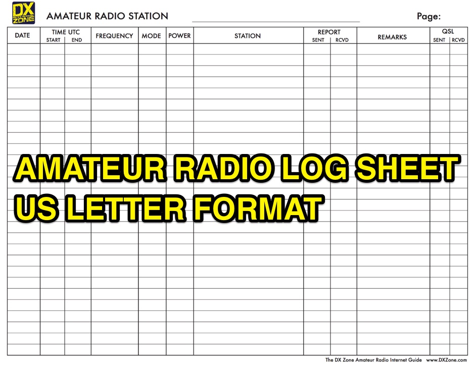 A free to download and print, amateur radio station log sheet in a paper US letter format
 -
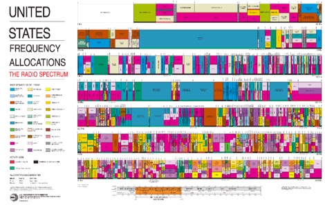 The radio spectrum in usa, PDF File representing the united stares frequency allocations in graphical mode, dated 2003
 -
 A **90-foot tall** top-loaded vertical antenna for the 160-meter band is detailed, constructed from aluminum irrigation tubing. The design incorporates four sets of four guy wires for structural stability, essential for an antenna of this physical size. This _monoband_ vertical is optimized for low-band operation, providing a robust solution for DXing and contesting on 1.8 MHz. The document includes specific construction methods for assembling the aluminum irrigation tubing sections and securing the guy wires. While a full NEC model is not explicitly provided, the physical dimensions and construction materials are sufficient for replication by experienced builders. The antenna's height and top-loading configuration are critical for achieving efficient radiation on 160 meters, particularly in minimizing ground losses.
 -
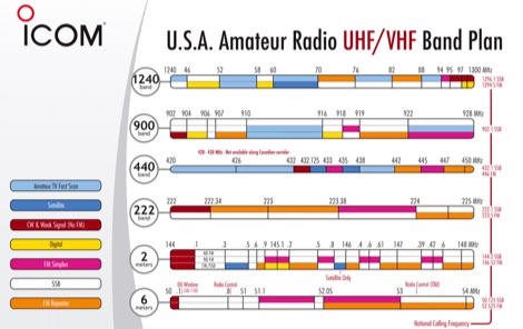 Download the PDF with USA Amateur radio HF band plan and common country prefixes updated in 2008 by Icom
 -
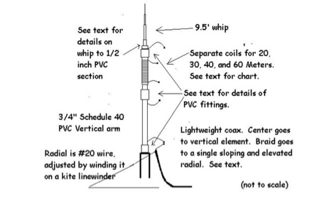 W3FF article about the buddistick portable vertical antenna in a PDF file
 -
 An interesting article on NVIS antennas, explaining basics of NVIS antennas and the main usage of this particular aerials by Patricia Gibbons
 -
 KaWin is a Windows software that supports multiple Kantronics TNCs and multiple radio transceivers with an intuitive, graphical interface, setting a new standard of performance for digital radio communications. Software is not supported anymore.
 -
 The resource details the construction and performance of a dual-band 40/30 meter _Moxon_ antenna, evolving from an initial single-band 30-meter design that failed in a storm. It specifies materials such as four 10-meter fishing rods, galvanized iron TV antenna support pipes, 1mm diameter PVC-covered copper wire, and a piece of 75-ohm TV satellite cable for feedline. The document outlines the iterative design process, including initial resonance measurements of 9.9 MHz for 30 meters and subsequent recalculations to shift the center frequency by 300 kHz using _Moxon software_. Initial testing on a roof yielded SWR readings of 1.4:1 at 7.200 MHz and 1.5:1 at 10.280 MHz. After installation atop a 30-meter tower, the final SWR measurements were 1.1 at 7.130 MHz and 1.4 at 10.230 MHz, with a notable 30 dB front-to-back ratio on 40 meters. The 30-meter performance, while good, showed a front-to-back ratio of approximately 15 dB, suggesting a slightly high resonance. The antenna's placement on a 700-meter hill, with a significant ground drop in certain directions, is noted as a potential factor in its excellent DX performance, enabling daily contacts with the USA West Coast on 30 and 40 meters with 100 watts.
 -
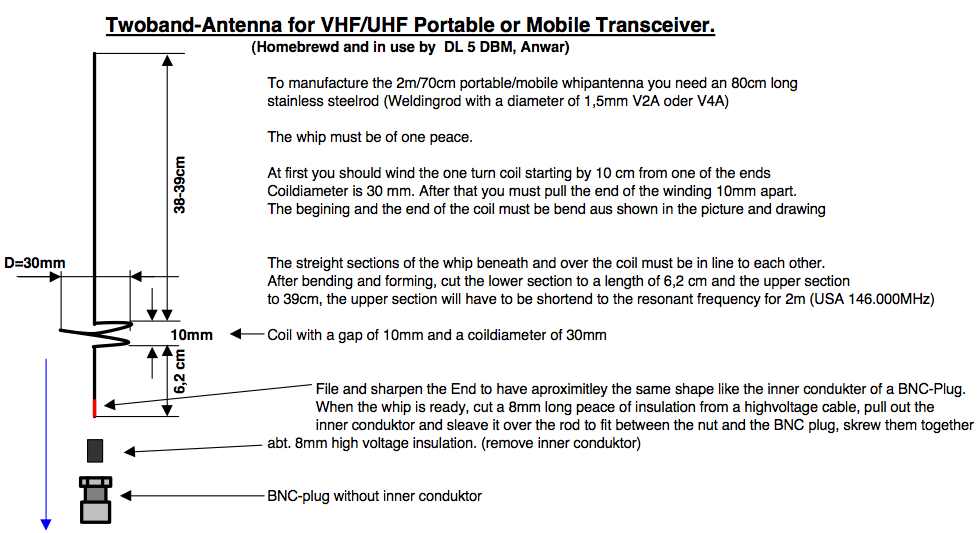 A project by DL5DBM for a VHF UHF antenna suitable for handheld transceivers
 -
 Excellent article on limiting noise using chockes by Chuck Counselman, W1HIS
 -
 WinTone v2.02 is a windows DTMF Decoder, run on old windows versions only.
 -
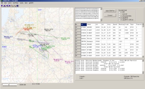 adsbScope is a freeware Windows application designed for processing _ADS-B_ (Automatic Dependent Surveillance-Broadcast) frames received from a compatible decoder. It identifies aircraft, calculates their real-time positions, and presents flight parameters in both alphanumeric tables and a graphical display. The software interfaces via a virtual COM port, receiving raw frames to provide detailed situational awareness, including a global coordinate grid, continental coastlines, over 4,000 **airport** locations, and major cities. Users can overlay OpenStreetMap tiles and view world state boundaries, with each tracked aircraft rendered with labels showing altitude, speed, heading, squawk code, and flight identifiers. When paired with the adsbPIC-decoder, adsbScope enables advanced hardware control, allowing users to toggle data filters for specific frames like DF17/18/19, adjust analog signal thresholds for reception fine-tuning, and manage system resets or bootloader activation directly from the PC. This functionality provides a customizable toolkit for hobbyist radar listeners, offering a robust alternative to commercial tools for processing aircraft data. The software displays up to **1090 MHz** transponder data and can track aircraft up to 250 nautical miles.
 -
 The W8JK is a famous and effective DX antenna, first built by John Kraus, W8JK, in 1937. A Beam antenna with two parallel dipoles driven with opposite phase, with a close spacing of an eighth of a wavelength.
 -
 This program descrambles band inverted encrypted transmissions, usually found on VHF/UHF. It uses a NCO (numerical controlled oscillator) to re-produce the originally inverted audio band.
 -
 A simple keyer which can be built for as little as $6 with some junk box parts. Although this circuit is not a true iambic keyer, it is capable of producing perfectly sounding CW.
 -
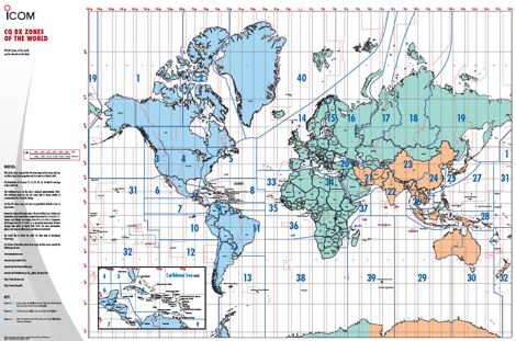 The ITU and CQ Zones Map is a printable two-page PDF provided by Icom, displaying the world divided into ITU and CQ Zones. The purpose is to assist radio amateurs in identifying and understanding these zones for communication purposes.
 -
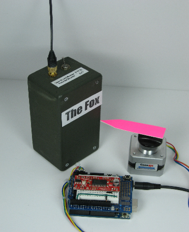 Ham Radio applications with the Arduino micro-controller presentation
 -
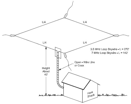 An horizontal full wave wire loop antenna for the 80 meters band by W4HM
 -
 Presents G0GSF Brian's ZS6BKW antenna, a refined iteration of the classic G5RV, offering improved performance across multiple HF bands. The design emphasizes specific radiator and ladder line lengths to achieve lower SWR on 40m, 20m, 17m, 12m, and 10m, making it a practical choice for operators seeking a single wire antenna solution. The document includes critical dimensions for the flat-top and the 450-ohm ladder line section, which are key to its multiband resonance characteristics. Unlike the original G5RV, the ZS6BKW aims for direct 50-ohm feedpoint impedance on several bands, reducing the need for an external antenna tuner. My field experience with similar optimized dipoles confirms that precise construction, particularly the ladder line length, is paramount for realizing the intended SWR benefits. This design offers a compelling alternative for hams with limited space or those preferring a less complex antenna system.
 -
 WA2UGT X-beam antenna for 17 meters band
 -
 Based on a W4TWW project and modified by KN4LF
 -
 Demonstrates building a basic _VOX circuit_ to add voice-operated transmit functionality to HF transceivers that lack this feature. The design utilizes a _1458 dual op-amp_ (two 741 op-amps in one package) to amplify microphone audio and act as a comparator, driving an NPN switching transistor for PTT control. A capacitor, C2, provides the necessary delay before unkeying the PTT, with a variable resistor, R6, allowing adjustment of the VOX level for specific microphones or voices. This low-cost circuit, detailed with a full parts list, offers a practical solution for hams seeking to enhance their budget HF rigs. The author, N1HFX, provides guidance on initial setup, including advice on microphone gain and the use of headphones to prevent speaker audio from re-keying the transceiver. Modifications for adjusting delay time are also included, suggesting increasing R8 to 10K for more delay or decreasing C2 to 22µF for less.
 -
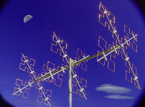 A Quad Fractal Antenna for 20 meters band by F3DD
 -
 This article describes a simple, inexpensive, dipole antenna that will rival the performance of a ten-meter beam.
 -
 NuMorse 2.20.0.0 for Win 7/Win 8/XP/Vista/Win 10 A complete rewrite of the original NuMorse used by thousands of radio amateurs to gain and upgrade their licenses. NuMorse offers an intermediate feature set that is somewhere between the lean and mean NuCode program and the vast array of features supported by NuMorse Professional. But NuMorse is no cut-down program. It has several unique features not found in other Nu-Ware products as well as a compact and intuitive set of controls that you will be able to learn quickly.Product is no more developed and out of support.
 -
 Freeware Hellschreiber decoding program for windows by Nino Porcino
 -
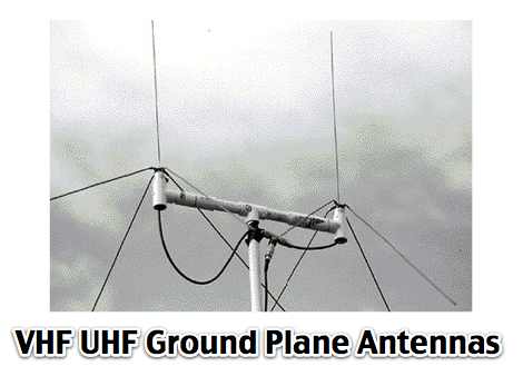 Phased array Ground Planes antennas for 144 Mhz
 -
 Download ex1726 a 32-bit DOS radio control program for the ICOM M700PRO, M710 and M710-R NMEA computer interface.
 -
 Phased arrays of short vertical antennas. A technical notes from Butternut antennas on phased vertical arrays
 -
 The original G5RV antenna system consists of a center-fed horizontal 102' wire plus a 34' length of open-wire 525-Ohm feeder. Louis Varney, the antenna system's developer, intended two other features. Learn more at Cebik website
 -
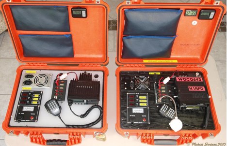 Radio Incident Command Kit project is described in this article loaded with many pictures and go-kit composition.
 -
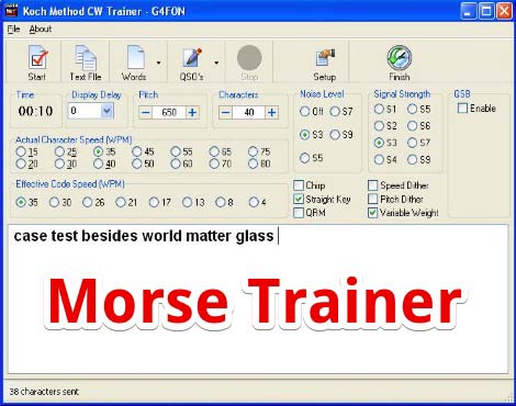 Mose Trainer by G4FON is a free windows morse code training program developed using the Koch method. Sends words simulating real morse code transmission, with QSB and QRM, allow change speed tone and many other settings. Download the kochmorsetrainer_install file and start learning Morse Code.
 -
 A PIC16F876 microprocessor-based digital SWR/WATTmeter project provides automatic operation across the 1.8 to 60 MHz frequency range. This design displays both SWR and P.E.P. power values, incorporating a bar graph on the second LCD line for instantaneous power tracking. The directional coupler utilizes a single-wire coil on a ferrite FT50-43 toroid, balanced with a 60 pF trimmer, and employs 1N5711 Schottky diodes for detection, ensuring linearity and a power range of 5 to 120 W. The software, developed by IW3EGT, compensates for diode voltage drop for precise readings, updating power every two seconds for stable display of modulated carriers, while the bar graph updates ten times per second for near real-time feedback. Calibration involves two phases: adjusting the directional coupler for minimum SWR on a 50-ohm dummy load at 28 MHz, and calibrating the microprocessor system by inputting a calculated power value (Power (Watt) = (Vout + 0.5)^2 / 100) at 14-21 MHz. The project includes PCB layouts for both the directional coupler (two-layer copper board) and the PIC module (single-sided), with specific instructions for component placement and shielding to prevent RF interference. The design allows for modification of power reading capability by varying the number of turns in the coupler coil, catering to different power levels.
 -
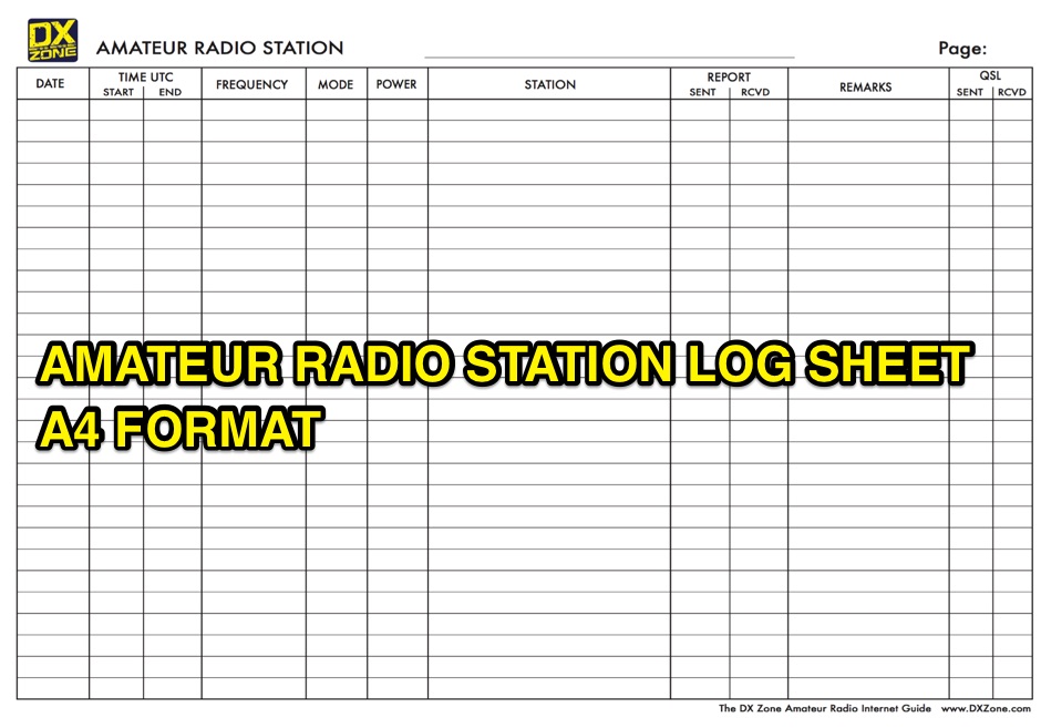 A free to download and print, log sheet in A4 paper format for amateur radio stations
 -
 A 40-meter reversible _Moxon rectangle_ antenna project details its construction and performance, featuring 51-foot long sides and 7.7-foot turned-in sections. The design incorporates a 16.5-foot boom, with elements spaced 1.1 feet apart, constructed from #14 covered wire. It utilizes two double-pole relays for switching between NE and SW directions, achieving F/B ratios up to 40 dB on CW and 30 dB on SSB, with distinct reflector stub settings for each mode. This antenna replaced a full-size 2-element Yagi, demonstrating comparable forward gain while offering superior F/B ratios and directional flexibility. _EZNEC_ modeling indicates only 0.2 dB less forward gain than the Yagi. The system uses no baluns, relying on half-wave feedlines and switched stubs for impedance matching. The antenna is tree-supported at 45 feet, with its effective radiation height modeled at 80 feet due to local terrain, enhancing its performance over a nearby lake.
 -
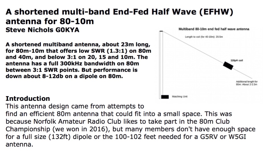 A shortened multiband antenna, about 23m long, for 80m - 10m bands with a low SWR (<1.3) on 80m and 40m, and < 3 till 10m. Bandwith on 80m is 300kHz
 -
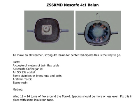 Making a 4:1 balun with a nescafe coffee jar lid and a toroid
 -
 The "Largest YU Moxon" document details the design and construction of a substantial multiband Moxon antenna, primarily for 80m, 40m, and 20m operation. It presents specific design parameters derived from NEC-based simulations, including a 4-element 80m Moxon with 37 dB F/B and 7.81 dBi gain on a 47m boom, a 4-element 40m Moxon with a bidirectional pattern, and a 6-element 20m Moxon optimized for specific side lobes. The resource provides precise element lengths and spacing in meters for each band, alongside measured SWR results across the 3.650-3.800 MHz, 7.000-7.100 MHz, and 14.000-14.350 MHz segments. The construction narrative outlines the challenges and solutions encountered by the YU team, including the use of trees for support, the creation of "ugly" air-choke baluns from RG-58 cable wound on plastic bottles for each band, and the meticulous process of attaching wires to a rope boom. It documents the physical dimensions of the vineyard site (47 x 38m) and the azimuth orientation (340 degrees) chosen for the antenna. The document is distinctively useful for its practical insights into large-scale antenna deployment in a field environment, offering real-world SWR measurements and anecdotal performance reports from CQWW contest operations. It includes numerous photographs illustrating the construction process, the team members, and the finished antenna structure, providing visual context to the technical details.
 -
 The varieties of twinlead J-Poles and some performance standards, L. B. Cebik, W4RNL
 -
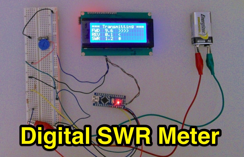 Inline RF Power & VSWR Meter. A DIY meter 0 to 30 Watt with Average and Peak. Circuit Description, Arduino Nano software code and part list to DIY your own Digital SWR Meter
 -
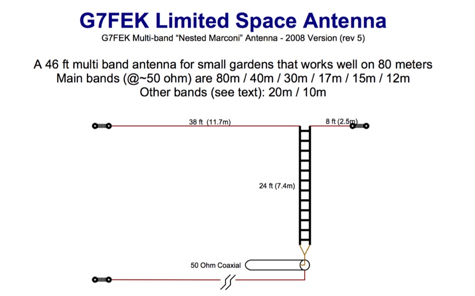 46ft multi-band antenna for small gardens. Works well on 80m. An excellent DX performer and is an ideal replacement for your half size G5RV
 -
 The total length of the inverted L is 240 feet, which is 7/16th of a wave length long. It has a 92 foot horizontal linear load section 1 foot above ground that terminates into a home-brewed parallel network tuner by KN4LF
 -
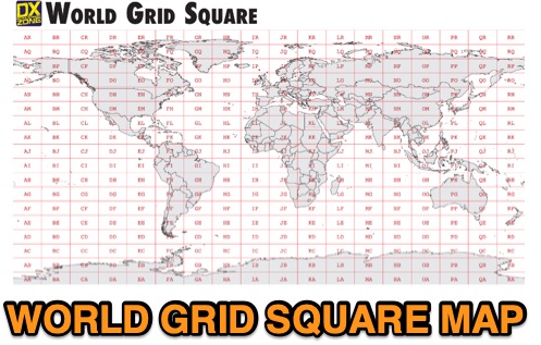 This free PDF file contains two Worldwide grid square maps. The first map displays the fields (first two letters of a maidenhead locator) while the second includes also squares (third and fourth digit) and it can be useful to determine what is your ham radio grid square. PDF file can be enlarged and scaled to A3 and higher dimensions.
 -
 Designing quagi and yagi antennas on 2 Meters, some preliminary notes by Cebik, W4RNL
 -
 A Primer for the new Packet Radio operator
 -
 Great first time J-pole project. Covers most of the basics. This small and thin design also makes it good for several stealth applications.
 -
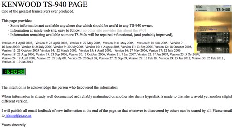 Comprehesive page on TS-940 TS-940 reference maintained by ZL4AI Jeff
 -
 When one operates at low power on SSB, speech processing becomes almost essential to get through the QRM. The circuit is a low cost speech processor that will perform well with a minimum of construction effort.