Search results
Query: RF
Links: 626 | Categories: 67
This query is too generic. Please try adding an additional term to focus your research.
Categories
- Manufacturers > Interfaces
- Technical Reference > Radio Frequency Interference
- Technical Reference > Amplifiers > RF Amplifiers Theory
- Technical Reference > RF Design
- Software > RF Design
- Technical Reference > Test Equipment > RF Probe
- Technical Reference > RF Safety
- Technical Reference > RF Signal Generators
- Technical Reference > Test Equipment > RF Sweep Generator
- Shopping and Services > RF Tubes
- Software > RF Coverage Mapping
- Technical Reference > Sound Card Radio Interfacing
- Shopping and Services > Accessories
- Radio Equipment > HF Amplifiers > Ameritron AL-80B
- Manufacturers > Amplifiers
- Technical Reference > Amplifiers
- Technical Reference > APRS
- Technical Reference > Attenuators
- Antennas > Baluns
- Radio Equipment > HF Portable Antenna > Buddipole
- Manufacturers > Cable and Connectors
- Shopping and Services > Cables and Connectors
- Technical Reference > Calculators
- Antennas > Feed Lines > Choke
- Antennas > Feed Lines > Coax Stubs
- Radio Equipment > HF Vertical Antenna > Cushcraft R5
- Manufacturers > Digital and Packet Radio
- Ham Radio > Clubs > Europe > UK > Eastern England
- Antennas > EH
- Radio Equipment > HF Transceivers > Elecraft K4
-
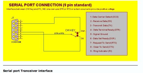 How to connect a mose key to a pc using the standard RS232 serial ports by F8EHO
 -

-
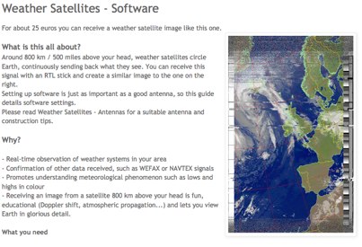 Complete guide to receive weather satelite images with a RTL SDR dongle and free software
 -
 The Megacycles combine the hobbies of amateur radio and bicycling. This group is not a club as there are no officers, dues or by-laws.
 -
 About DRM, the DRM standard, emission types, upfrading your old HF RX to DRM
 -
 This video will provide a foundation for understanding how power amplifier circuits work. If you are new to High Frequency Power Amplifier Circuit Design, this is the place to start.
 -
 Home Brew a 4-1000A RF power amplifier project by W4NFR
 -
 The current, the voltage, the impedance, the bandwidth, the polarization, and how the earth influences the famous radiation pattern.
 -
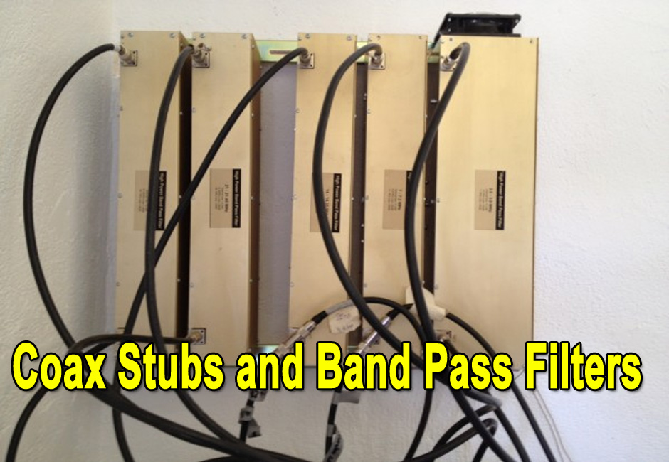 Will additional coax stubs improve Band Pass Filter performance?
 -
 A MacOSX antenna design and electronics/electrical tool package. It is a multipourpose application that allow antenna design and comomn calculations
 -
 A RF Probe circuit for the RADIO frequency experimenter to check the presence of a RF signal and also to measure its strength
 -
 Understanding the operational impact of Broadband over Power Line (BPL) on amateur radio communications is crucial for any radio amateur, especially given the potential for significant radio frequency interference (RFI). This ARRL tutorial delves into the technical aspects of BPL, explaining how the technology operates by transmitting data over existing electrical power lines, which can inadvertently radiate broadband noise across various amateur bands. My own field experience, particularly on the lower HF bands, has often involved tracking down noise sources that exhibit characteristics consistent with BPL emissions, making this a pertinent topic for maintaining clear receive conditions. The resource further details the specific FCC rules and regulations implemented to restrict BPL deployment. These regulations aim to protect licensed radio services, including amateur radio, from harmful interference. It outlines the technical standards and operational limitations imposed on BPL systems to minimize their impact on the electromagnetic spectrum, a critical aspect for contesters and DXers alike. For those engaged in RFI mitigation, the tutorial provides a foundational understanding of the regulatory framework that can be leveraged when addressing BPL-related interference issues. It serves as a valuable reference for hams seeking to comprehend the technical challenges and regulatory solutions surrounding this pervasive noise source.
 -
 Thierry LOMBRY, ON4SKY, develops in depth and with original pictures the long history of amateur radio all through the world from 900 BC to date.
 -
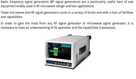 Essentials or basics of RF signal generators or microwave signal generators, their facilities, capabilities and how they work.
 -
 How to become an amateur radio ? by ON4SKY Review of general conditions to get licensed, examinations, regulation, CW, foreign calls, and more
 -
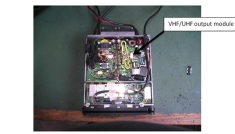 Replacing the Yaesu FT100D SRF7043 VHF/UHF RF MOSFET Power Amplifier
 -
 Getting squeaks and squawks from your H-T? Are pagers crunching your mobile rig's front end? Here's how intermod happens--and how to fight back!
 -
 ARRL page dedicated to RF Safety
 -
 A nice tutorial and the basics of the software defined radio, SDR, and links of software defined radios to JTRS, and general SDR receiver technology.
 -
 The _Sci.Electronics FAQ: Repair: RFI/EMI Info_ document, authored by Daniel 9V1ZV, provides a detailed analysis of computer-generated RFI/EMI, focusing on its impact on radio reception. It identifies common RFI sources such as CPU clock rates (e.g., 4.77 MHz to 80 MHz), video card oscillators (e.g., 14.316 MHz), and even keyboard microprocessors, all of which generate square-wave harmonics across HF and L-VHF regions. The resource outlines a systematic procedure for pinpointing RFI origins, including disconnecting peripherals and using a portable AM/SW receiver with a ferrite rod antenna to localize strong interference sources. The document categorizes RFI mitigation into shielding, filtering, and design problems, offering practical solutions for each. It recommends applying conductive sprays like _EMI-LAC_ or _EMV-LACK_ to plastic casings of radios, monitors, and CPUs to create effective Faraday cages, emphasizing proper grounding and avoiding short circuits. For filtering, the guide suggests using line filters, ferrite beads, and toroids on power and data lines, and small value capacitors (e.g., 0.01 uF for serial/parallel, 100 pF for video) to shunt RFI to ground. It also discusses the use of bandpass, high-pass, low-pass, and notch filters on the receiver front-end or antenna feed to combat specific in-band noise.
 -
 Sense The Right Way To Go With The HANDI-Finder
 -
 An overview of coax cable often called coaxial feeder or RF cable, used to feed antennas and deliver radio frequency power from one point to another
 -
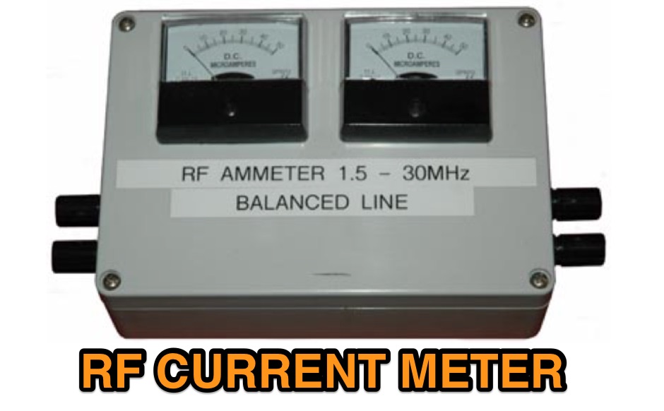 This R.F. current meter was developed to assist in measuring line currents in balance feed lines as used in the All Band HF Antenna.
 -
 Operating a ham station often involves encountering radio frequency interference (RFI), RF feedback, or RF burns, which are frequently misattributed to poor equipment grounding. This resource meticulously dissects these assumptions, asserting that RF grounds on the operating desk often merely mask more significant system flaws. It identifies five primary causes for RF problems, including antenna system design flaws, proximity of the antenna to the operating position, DC power supply ground loops, equipment design defects, and poorly installed connectors or defective cables. The content emphasizes that issues like "hot cabinets" or changes in SWR when connecting a ground indicate substantial RF flowing over wiring or cabinets, a phenomenon known as common-mode current. The article provides detailed explanations of common-mode current generation, particularly from single-wire fed antennas like longwires, random wires, and OCF dipoles, which inherently present high levels of RF in the shack. It also illustrates how vertical antennas, lacking a perfect ground system, can excite feed lines with significant common-mode current. Through simulations, the author demonstrates how a dipole without a proper _balun_ can cause RF problems at the operating desk, showing current patterns and voltage distributions on feed line shields. The discussion extends to the proper application of _RF isolators_ and _ferrite beads_, clarifying their role in modifying common-mode impedance on cable shields and cautioning against their use as a band-aid for fundamental system defects. The resource advocates for correcting the actual source of RF problems, such as antenna system issues or poor connector mounting, rather than relying on internal shack grounding or isolators. It highlights that properly functioning two-conductor feed lines, like coaxial or open-wire lines, should result in minimal RF levels at the operating position, even without a desk RF ground. The author shares personal experience, noting that his stations since the late 1970s have operated without RF grounds at the desks, relying instead on proper antenna system design and feed line integrity.
 -
 Information about RF driven lamps
 -
 RF Current measurements on a Long Wire W3EDP antenna
 -
-
 This is an Arduino-based rotator interface that interfaces a computer to a rotator or rotator controller, emulating the Yaesu GS-232A/B and Easycom protocols which are supported by a myriad of logging, contest, and control programs.
 -
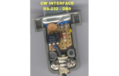 A RS-232 to DB9 CW Radio interface with schematic diagram to connect your pc running CT by K1EA or Writelog to your keyer.
 -
 How to interface the Icom IC-7300 to RF Power amplifiers. Menu settings, cable connections and recommendations on how to avodi common errors that could even damage either the amplifier or the IC-7300
 -
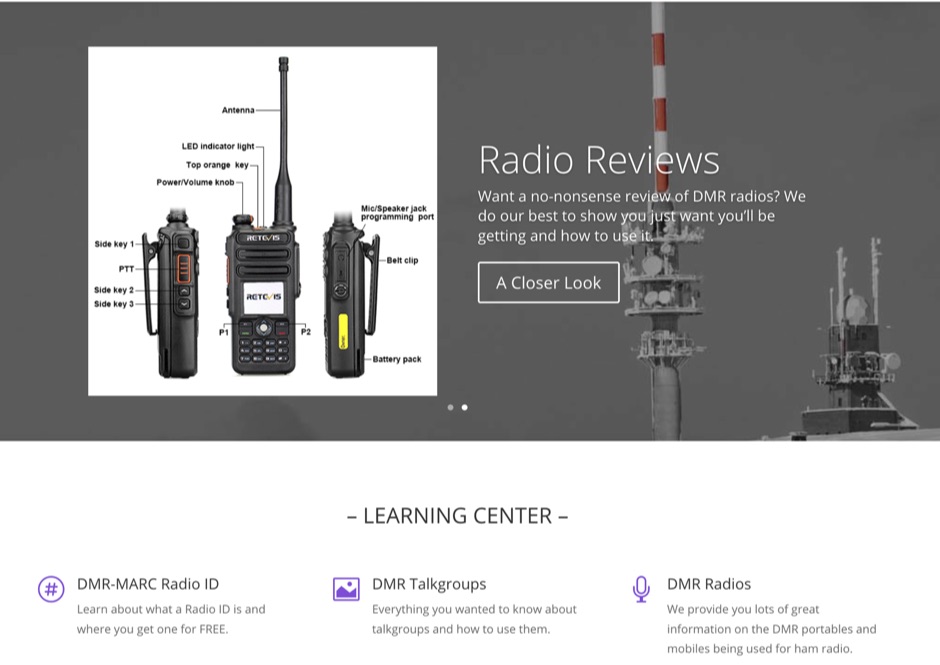 A beginners guide to DMR. This web site cover all aspects of DMR and is a valuable resource for those who want to get started with DMR.
 -
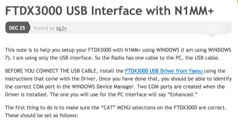 This note is to help you setup your FTDX3000 with N1MM+ using WINDOWS via USB port
 -
 RF Solutions is your authorised distributor of superior amateur radio products in Australia, New Zealand, and the Asia Pacific region
 -
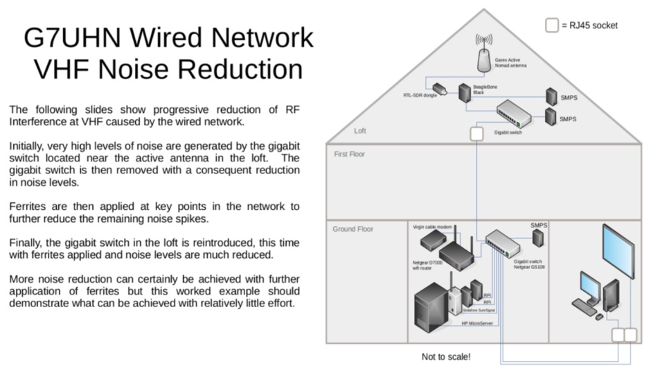 How to reduce and eliminate the RF interference at VHF caused by the wired network
 -
 A synthesized 2.3 GHz Amateur Television (ATV) transmitter design, conceived by Ian G6TVJ, is presented, targeting broadcast-quality video performance on the 13cm band and extending up to 2.6 GHz. The core of the design utilizes a commercial Z-comm Voltage Controlled Oscillator (VCO) that tunes from 2.2-2.7 GHz, providing a +10 dBm output and simplifying RF alignment. This VCO's stability, originally intended for narrowband applications, readily accepts high-frequency video modulation, contributing to the transmitter's robust performance. The exciter stage, incorporating a Mini Circuits VNA 25 MMIC amplifier, boosts the signal to +16dBm, while a Plessey SP4982 prescaler divides the output frequency for the synthesizer. The synthesizer employs a Motorola MC145151 CMOS parallel IC, favored over the common Plessey SP5060 for its superior video modulation characteristics and ease of programming without microprocessors. This choice addresses issues like LF tilt and distorted field syncs often seen with SP5060 designs, particularly when operating through repeaters or over long distances. The MC145151 divides the signal further, enabling precise frequency stepping, with programming handled by EPROMs for channel selection and LED display. The loop filter network, critical for video integrity, was developed through experimentation to prevent the PLL from reacting to video modulation, ensuring a clean transmitted picture. The transmitter incorporates a Down East Microwave commercial power amplifier module, delivering approximately 1.6W output, driven by the exciter through a 3dB attenuator. Construction involves surface-mount SHF components on micro-strip lines etched onto double-sided fiberglass board, housed within a tinplate box. The design boasts no AC coupling in the video path, preserving low-frequency response, a common failing in other ATV transmitters. Performance tests with a 50Hz square wave revealed no LF distortion, and a calibrated "Pulse & Bar" signal showed a near 100% HF response, demonstrating its capability for high-quality ATV transmissions.
 -
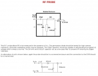 This RF probe circuit allows RF to be measured in the presence of DC
 -
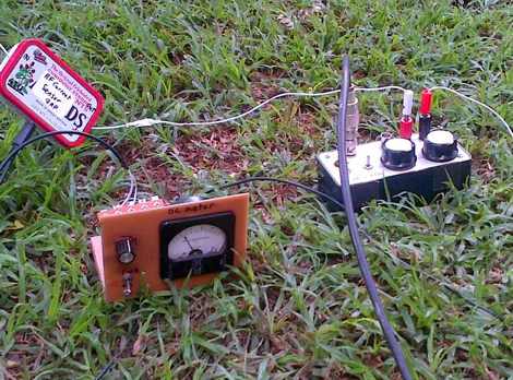
 Measuring antenna current with and RF Ammeter
 -
 Interfacing the IC706MKIIG for Soundcard & TNC modes
 -
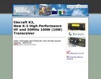 I0GEJ page on the Elecraft K3 transceiver
 -
 Radio Free Europe/Radio Liberty website provides news and information on various topics beyond borders. It includes top stories, visuals, newsletters, and in-depth coverage. The content is useful for staying updated on global events and perspectives.
 -
 Killing RFI from your PC without turning it off
 -
 The CAT and audio interface version 3 project by PA5CA presents a comprehensive solution for integrating amateur radio transceivers with computer sound cards, facilitating digital mode operation and CAT control. It includes detailed schematics for the interface circuitry, illustrating the isolation transformers for audio paths and optocouplers for CAT data lines, ensuring robust electrical separation between radio and PC. The resource also provides PCB layouts, enabling constructors to fabricate their own boards for this specific design. The project outlines the component selection and assembly process, emphasizing the use of readily available parts to build a reliable interface. It addresses common challenges in sound card interfacing, such as ground loops and RF interference, through its isolated design. This construction guide offers practical insights into building a functional interface, making it suitable for hams interested in DIY radio accessories for digital modes like FT8, RTTY, and PSK31.
 -
 1.5 dB of matched line loss can be calculated for a given transmission line using this online tool, which employs a model calibrated from empirical data. The calculator allows radio amateurs to input specific transmission line types, such as _RG-8_ or _RG-58_, and then determine the expected signal attenuation. This is crucial for optimizing antenna system efficiency and understanding power delivery to the radiating element, especially for HF and VHF operations where feedline losses can significantly impact performance. Beyond matched loss, the calculator also provides an estimate for mismatched loss if the Standing Wave Ratio (SWR) is specified. This feature helps operators quantify the additional power loss due to impedance discontinuities between the transceiver, feedline, and antenna, which is a common concern in amateur radio installations. Accurate loss calculations are vital for effective station design and for predicting actual radiated power. The tool's utility extends to various operating scenarios, from fixed station setups to portable deployments, aiding in the selection of appropriate feedline lengths and types to minimize signal degradation. Understanding these losses is a fundamental aspect of maximizing the effectiveness of any amateur radio antenna system.
 -
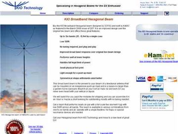 Performance data of the KIO Hexagonal Beam antenna
 -
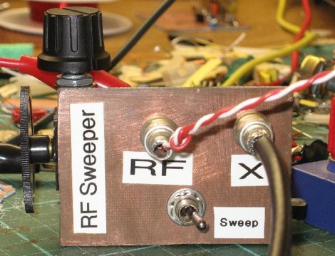 Hand made RF sweeper made to adjust the pass band of crystal filter
 -
 A summary or tutorial about the basics of the spectrum analyzer, what it is and what it is used for.
 -
 SPX Communication Technologies, operating under the TCI International brand, presents a range of radio frequency (RF) solutions primarily for government, defense, and commercial sectors. The offerings include advanced systems for spectrum monitoring, communications intelligence (COMINT), and high-frequency (HF) and medium-frequency (MF) broadcasting and communication antenna systems. Specific product lines encompass _Blackbird_ COMINT systems, _Scout_ spectrum monitoring receivers, and various antenna arrays designed for robust performance in challenging RF environments. The resource details the capabilities of these systems, such as wideband signal detection, direction finding (DF), and signal analysis, crucial for intelligence gathering and regulatory compliance. It also highlights the engineering behind their antenna designs, which are optimized for specific frequency ranges and operational requirements, including high-power broadcast applications and secure military communications. The information presented emphasizes the integration of hardware and software for comprehensive RF situational awareness. The company's focus on empowering partners to "Command the Spectrum" underscores its commitment to delivering critical tools for signal interception, analysis, and management across diverse operational landscapes.
 -
 Mobile RFI, often manifesting as persistent noise in the receiver even with the antenna disconnected, frequently originates from the vehicle's power supply system. This guide details systematic troubleshooting steps, beginning with isolating the radio from the car's 12-volt supply to confirm the power system as the noise source. It emphasizes the critical importance of drawing power directly from the battery using **heavy gauge wire**, bypassing the fuse block to leverage the battery's natural capacitance for RFI suppression and ensuring a solid RF ground. Proper routing of power lines through the firewall is also covered, advocating for dedicated grommeted holes to prevent inductive coupling from other wiring harnesses. The article stresses the necessity of fusing both positive and negative leads from the battery, a crucial safety measure to prevent damage to the rig and mitigate high-current risks should the battery's engine block ground become compromised during service. Addressing **alternator whine**, a common high-pitched noise that varies with engine speed, the resource suggests checking battery connections and the alternator-to-battery harness for looseness or corrosion. It also mentions the utility of adding an external RF noise suppression capacitor in parallel with the alternator's internal capacitor for enhanced filtering, and the effectiveness of commercially available in-line power supply filters.