Search results
Query: feed
Links: 563 | Categories: 11
Categories
- Antennas > Feed Lines
- Antennas > Resonant Feedline Dipole
- Antennas > Baluns
- Shortwave Radio > Broadcasters
- Antennas > Microwave
- Antennas > Feed Lines > Open Wire
- Internet and Radio > Police Scanners
- Radio Scanning > Police Scanning
- Radio Scanning > RailRoad
- Internet and Radio > Tutorials
- Internet and Radio > Web Cams
-
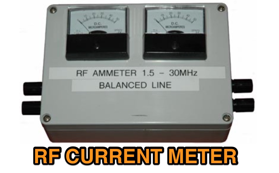 This R.F. current meter was developed to assist in measuring line currents in balance feed lines as used in the All Band HF Antenna.
 -
 Operating a ham station often involves encountering radio frequency interference (RFI), RF feedback, or RF burns, which are frequently misattributed to poor equipment grounding. This resource meticulously dissects these assumptions, asserting that RF grounds on the operating desk often merely mask more significant system flaws. It identifies five primary causes for RF problems, including antenna system design flaws, proximity of the antenna to the operating position, DC power supply ground loops, equipment design defects, and poorly installed connectors or defective cables. The content emphasizes that issues like "hot cabinets" or changes in SWR when connecting a ground indicate substantial RF flowing over wiring or cabinets, a phenomenon known as common-mode current. The article provides detailed explanations of common-mode current generation, particularly from single-wire fed antennas like longwires, random wires, and OCF dipoles, which inherently present high levels of RF in the shack. It also illustrates how vertical antennas, lacking a perfect ground system, can excite feed lines with significant common-mode current. Through simulations, the author demonstrates how a dipole without a proper _balun_ can cause RF problems at the operating desk, showing current patterns and voltage distributions on feed line shields. The discussion extends to the proper application of _RF isolators_ and _ferrite beads_, clarifying their role in modifying common-mode impedance on cable shields and cautioning against their use as a band-aid for fundamental system defects. The resource advocates for correcting the actual source of RF problems, such as antenna system issues or poor connector mounting, rather than relying on internal shack grounding or isolators. It highlights that properly functioning two-conductor feed lines, like coaxial or open-wire lines, should result in minimal RF levels at the operating position, even without a desk RF ground. The author shares personal experience, noting that his stations since the late 1970s have operated without RF grounds at the desks, relying instead on proper antenna system design and feed line integrity.
 -
 Baltimore County Scanner Radio - Live feed
 -
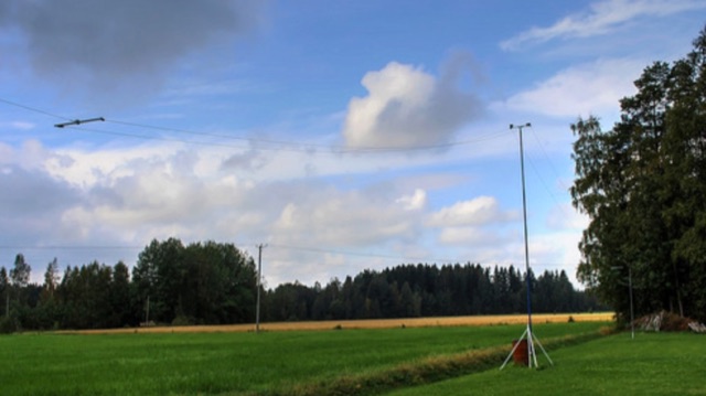 T2FD is a 600-900 ohms folded dipole, terminated with resistor. Feed impedance is coupled with 50/600 ohms voltage balun. It is a wide band antenna with rather low SWR over the full designed frequency range: antenna tuner is seldom needed.
 -
 The M0PLK multiband delta loop antenna project details the construction of a non-resonant, bidirectional antenna designed for 20-10m operation, requiring an external antenna tuner. The design utilizes two 5.65m aluminum tubes arranged at right angles, with 2x 2.80m antenna wires converging into a 2.30m ladder line, feeding a 1:4 balun. The resource provides a comprehensive parts list, including specific dimensions for aluminum tubes (25mm, 20mm, 16mm outer diameter), DX-Wire FS2, and custom 3D-printed components like a middle insulator, tube end caps, and ladder line spacers, with STL files provided. Construction steps cover base plate fabrication from a 300x300x4mm aluminum sheet, balun assembly, tube preparation with slits and threaded holes, and wire attachment with strain relief. Initial VSWR measurements are presented, indicating performance in line with expectations across the target bands. The author reports successful SSB test QSOs to the USA on 10, 12, 15, 17, and 20m immediately after completion. The project highlights the antenna's bidirectional pattern, noting the need for a lightweight, remote-controlled rotator to fully utilize its directional capabilities. Comparisons are drawn to the Cobweb antenna, with the M0PLK design cited for its reduced local QRM pickup. The article references external sources, including M0AWS's detailed report and PC modeling, along with other construction variants and commercial assembly instructions, providing a robust foundation for replication.
 -
 Current program schedules, RealAudio feeds, and listening tips from Belgian Public Radio which broadcasts worldwide in Dutch, German, French and English.
 -
 Constructing a compact directional antenna for the 17-meter band, this resource details the build process for a Moxon rectangle, a two-element Yagi variant with folded-back elements. It covers the antenna's evolution from the _VK2ABQ beam_ and provides specific dimensions for a version built using fishing pole whips. The content includes a discussion of the antenna's radiation pattern, feedpoint impedance, and its inherent front-to-back ratio, which is often superior to a standard two-element Yagi. Practical considerations for element spacing and material choices are also addressed, alongside a visual representation of the antenna's physical layout. Performance data presented includes a comparison showing the Moxon rectangle's **2.5 dB gain** over a half-wave dipole and a front-to-back ratio of **20 dB**. The resource also touches upon the antenna's relatively wide bandwidth for a two-element beam and its suitability for portable operations due to its compact footprint. It offers insights into optimizing the design for specific operating conditions and discusses the advantages of its lower take-off angle compared to omnidirectional wire antennas, making it effective for DX contacts on the 17-meter band.
 -
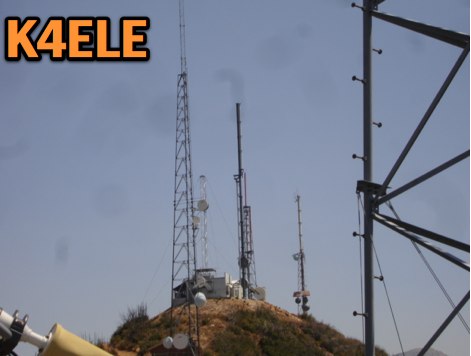 Amateur radio repeater scanner at Pomona California
 -
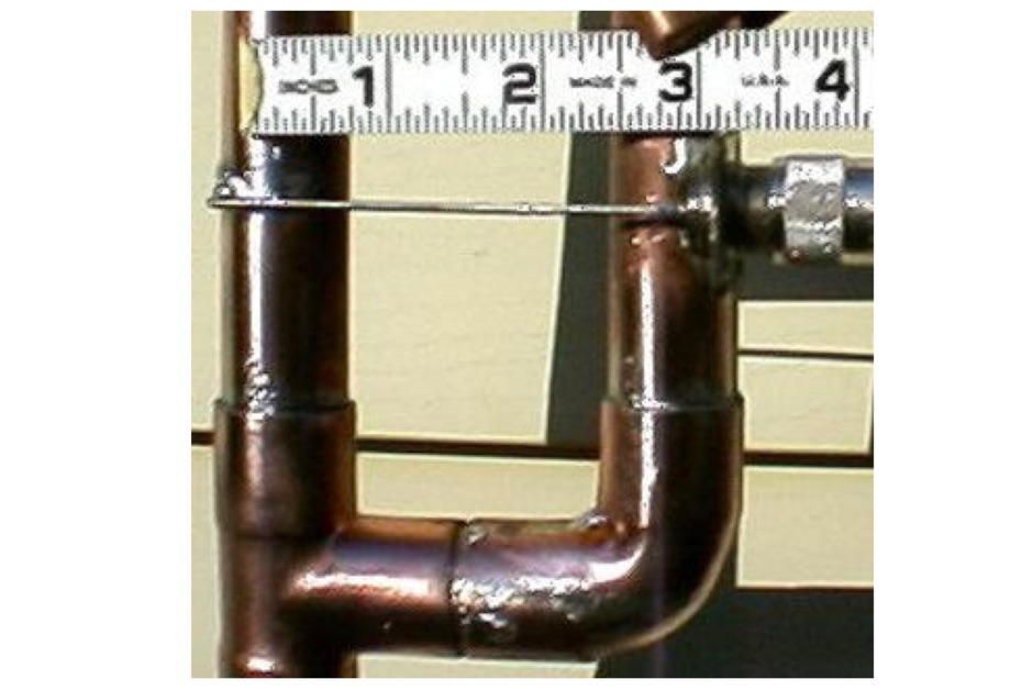 A copper J Antenna for 144 and 430 article with design, feeding methods and pictures
 -
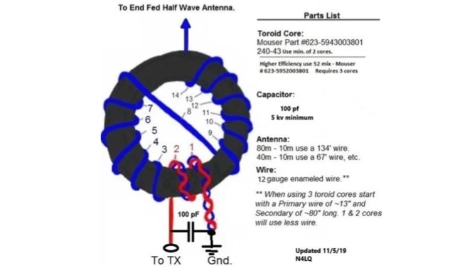 1:49 UNUN using two stacked FT240-43 cores for end fed halfwave antenna. To match the end fed half wave antenna to the coaxial feeder, it is necessary to have a matching network or transmission line transformer.
 -
 Essentially, a choke balun is designed to 'divorce' your antenna from the feed line. if your feed line is coaxial cable then you don't want it to be part of your antenna. you want to be able to deliver all your power to the radiator itself, i.e. 'the antenna'. a choke balun does this admirably
 -
 A 2m band Moxon antenna design is presented, centered at 145.2 MHz, with dimensions derived from Moxgen software. The design features a calculated 6 dBi gain, an 80-degree beamwidth, and an impressive 43 dB front-to-back ratio with minimal back lobes, concentrating RF energy in the forward direction. The antenna is balanced to 50 Ohms, facilitating direct feed. SWR sweep data from 144 MHz to 146 MHz demonstrates a near 1:1 SWR at the center frequency, maintaining healthy SWR values across the entire 2m amateur band. This performance is comparable to a 3-element Yagi, yet the Moxon offers advantages in compact size and ease of mast mounting, making it suitable for various operating environments.
 -
 This tutorial will get you on the road to running your own live scanner feed on the Internet, be it railroad, fire/ems or law enforcement related.
 -
 Council Bluffs area Sheriff, Police, Fire, and State Police IOWA
 -
 The article, "Using 75 Ohm CATV Coaxial Cable," details methods for employing readily available 75-ohm CATV hardline in standard 50-ohm amateur radio setups. It addresses the inherent impedance mismatch and practical considerations, such as connector compatibility, for hams seeking cost-effective, low-loss feedline solutions. The resource specifically contrasts common 50-ohm cables like RG-8, RG213, and _LMR-400_ with 75-ohm hardline, highlighting the latter's lower loss characteristics, particularly at VHF and UHF frequencies. It explores two primary approaches to manage the impedance difference: direct connection with an acceptable SWR compromise and precise impedance transformation. The direct connection method acknowledges that a perfect 1:1 SWR is not always critical, especially when using low-loss coax. For impedance transformation, the article explains the use of half-wavelength sections of coax to reflect the antenna's 50-ohm impedance back to the transmitter, noting its single-frequency effectiveness. It also briefly mentions transformer designs using toroid cores and a technique involving two 1/12 wavelength sections of feedline for broader bandwidth. The content further clarifies the concept of _velocity factor_ for calculating electrical versus physical cable lengths, providing a generic formula for precise length determination. It notes that while half-wave matching is practical for 10 meters and above, it can result in excessively long runs for lower bands like 160 meters, potentially adding **250 feet** of cable. The article also mentions achieving a usable bandwidth of 28.000 MHz up to at least **28.8 MHz** on 10 meters with specific transformation techniques.
 -
 A 102-inch vertical whip, commonly a CB antenna, forms the core of this low-profile 10-meter antenna design, optimized for the 28 MHz band. The construction details specify three 8-foot radials made from scrap wire, connected to a common point. This simple yet effective setup is designed for ease of construction and deployment, making it accessible for operators with limited space or materials. The design emphasizes using readily available components, including PVC pipe for the mast and a SO-239 connector for the feedline, ensuring a straightforward build process for a resonant quarter-wave vertical. Field results indicate that this antenna provides good performance for local and DX contacts on 10 meters, despite its compact footprint. The author, N8WRL, shares practical insights into its construction and tuning, highlighting its suitability for temporary or permanent installations where a full-sized antenna might be impractical. Comparisons to more complex designs suggest that this low-profile vertical offers a respectable signal-to-noise ratio and effective radiated power for its size, proving that simple designs can yield satisfying on-air results.
 -
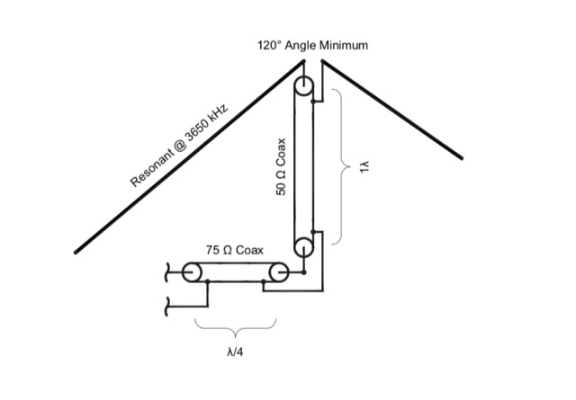 A dipole can be broadbanded by a number of techniques including by matching with resonant sections of transmission feed lines.
 -
 Listen to Cleveland Police Dispatch and Metro Housing Authority via the Live Audio Feed Web Player
 -
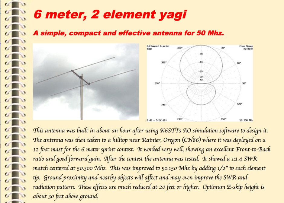 This 6 meter 2 element yagi antenna is simple, compact and effective antenna for 50 Mhz. The design antenna was optimized with AO for best match to 50 ohms, no matching network. A choke balun is recommended to decouple feedline currents.
 -
 This web article details the construction of a 4-meter band coaxial dipole antenna, designed for operation between **70.000 MHz and 70.500 MHz**. The resource provides a bill of materials and step-by-step assembly instructions for a half-wave dipole constructed from _RG-58_ coaxial cable. The design specifies a direct 50 ohm feedpoint impedance, eliminating the need for an external matching network. Construction photographs illustrate the stripping and soldering processes for the coaxial cable elements, ensuring proper electrical connection and physical integrity. The article includes specific dimensions for the radiating elements, derived from calculations for the 70 MHz band. The project outlines the physical dimensions required for resonance at 70 MHz, with the outer braid forming one half and the inner conductor forming the other. The feedline connection is directly to the coaxial dipole's center, maintaining a 50 ohm characteristic impedance. While the article does not present SWR plots or VNA sweeps, it focuses on the mechanical construction and dimensional accuracy for achieving a functional 4-meter dipole. The design is intended for fixed station use, with no specific mention of polarization or height above ground, but implies a standard horizontal orientation for dipole operation. DXZone Focus: Web Article | 4m Coaxial Dipole | Construction Guide | 50 ohm Feed
 -
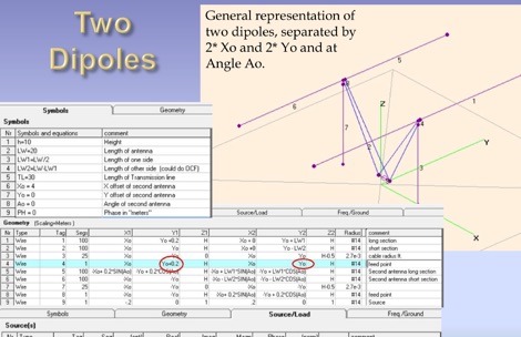 Presentation about Practical Antenna Modeling Using the NEC Codes with examples of HF wire antennas and 4NEC2. How to define and edit the models, Running the simulations, Work some examples, Variables usage, Deal with Feed Lines and ground
 -
 1.5 dB of matched line loss can be calculated for a given transmission line using this online tool, which employs a model calibrated from empirical data. The calculator allows radio amateurs to input specific transmission line types, such as _RG-8_ or _RG-58_, and then determine the expected signal attenuation. This is crucial for optimizing antenna system efficiency and understanding power delivery to the radiating element, especially for HF and VHF operations where feedline losses can significantly impact performance. Beyond matched loss, the calculator also provides an estimate for mismatched loss if the Standing Wave Ratio (SWR) is specified. This feature helps operators quantify the additional power loss due to impedance discontinuities between the transceiver, feedline, and antenna, which is a common concern in amateur radio installations. Accurate loss calculations are vital for effective station design and for predicting actual radiated power. The tool's utility extends to various operating scenarios, from fixed station setups to portable deployments, aiding in the selection of appropriate feedline lengths and types to minimize signal degradation. Understanding these losses is a fundamental aspect of maximizing the effectiveness of any amateur radio antenna system.
 -
 A 50.200 MHz Moxon antenna for the 6-meter band is detailed, providing practical construction guidance for amateur radio operators. The design utilizes 3/4" aluminum angle stock for the elements, joined with wood molding and 1/4 x 20 hardware. Key components include an SO-239 connector for the feedpoint and a **choke balun** made from coiled RG-58 coax, ensuring proper impedance matching and minimizing common mode current. The antenna measures approximately 29 inches deep by just under 7 feet long, making it suitable for portable operations. Specific dimensions, based on **Cebik's nomenclature**, are provided for the driven element and reflector. The resource also offers modeling hints, suggesting an effective element diameter of 1 inch for software simulations and emphasizing element sizing based on corner screws rather than end-to-end measurements.
 -
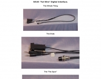 Constructing a digital interface for the Elecraft K2 transceiver, this resource details the "Fat Wire" design by WG4S. It demonstrates how to integrate a sound card for digital modes, outlining specific connections to the K2's microphone jack and internal audio path. The author shares practical insights from his build, including the use of _RG-62_ coax for its flexible braid and the strategic placement of components like the 2.2K resistor and _2N2222_ transistor. The guide provides a breakdown of the interface's internal wiring, specifying connections for AF In (pin 1), AF Out (pin 5), PTT (pin 2), and Ground (pin 7) on the K2's microphone connector. It also covers the external connections to a laptop's headphone and line-in jacks, along with a DB-9 connector for PTT control via _DTR_ or RTS lines. The author notes that his laptop's headphone output level was sufficient for the K2, negating the need for an attenuator. Reflecting on the design, the author, Dan WG4S, acknowledges a later suggestion to house the components directly within the DB-9 shell for a more compact build. This iterative feedback highlights the ongoing evolution of DIY ham radio projects and the community's collaborative spirit in refining designs.
 -
 How to setup a proper antenna feed line with a particular attention to RFI by K0GKJ
 -
 Maxdao: offer you 7/16, N coaxial connectors, jumper cables, feeder clamps and grouding kits, surge arresters & brackets, wall entries and microwave components used in base tower, power dividers, couplers
 -
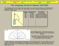 The radiating part is the vertical half of the dipole. You get nearly radiation in all directions, the second half must not be in 180°. The table below show how we get an impedance for direct feeding of 50Ohm coax. by DK7ZB
 -
 Listen to live police radio scanner from Dallas
 -
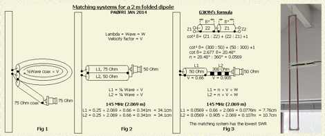 Matching with a half wave or wuarter wave coaxial cable is pretty well known, but an existing 1961 system to do that with two one-twelfth-wavelength transmission lines.
 -
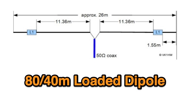 A dual band dipole antenna for 40 and 80 meters band. Total lenght of 26 meters, foreseen two coils at aprox 11 meters distance from center feed.
 -
 Listen to live radio scanner feed of Dallas Police 1 Central - 2 North East
 -
 The resource examines the operational characteristics and potential of Moxon Yagi antennas, drawing insights from Les Moxon's work and subsequent NEC modeling. It presents simulated current distributions and radiation patterns for a 40-meter Moxon, comparing its performance against a standard 2-element Yagi on the same band. Specific data points include forward gain, front-to-back (F/B) ratio, and feedpoint impedance, which are critical parameters for antenna design and optimization. Further analysis extends to a 20-meter Moxon, detailing its gain, F/B ratio, and SWR bandwidth across the band. The discussion highlights the Moxon's compact footprint and its ability to achieve respectable performance metrics, making it a viable option for hams with limited space. The content provides a technical assessment of the Moxon's advantages in terms of pattern purity and impedance stability compared to other compact directional arrays. The article also touches upon the practical considerations for constructing and deploying Moxon antennas, emphasizing the trade-offs between physical size and electrical performance. It includes graphical representations of antenna currents and radiation patterns, offering visual aids to understand the theoretical concepts discussed.
 -
 Live scanner feeds for the Fire department for various sectors of the San Francisco Bay area.
 -
 Transferring Radio Frequency Energy from Your Transmitter to Your Antenna by Don Keith N4KC
 -
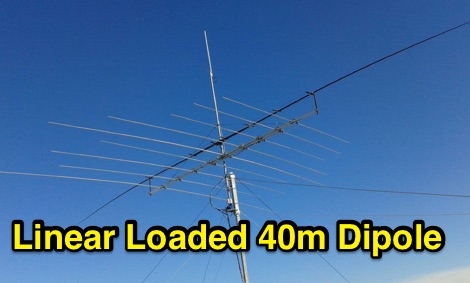 A simple dipole for 40m band feeded with 450-Ohm openwire feedline includes MMANA Gal files to download
 -
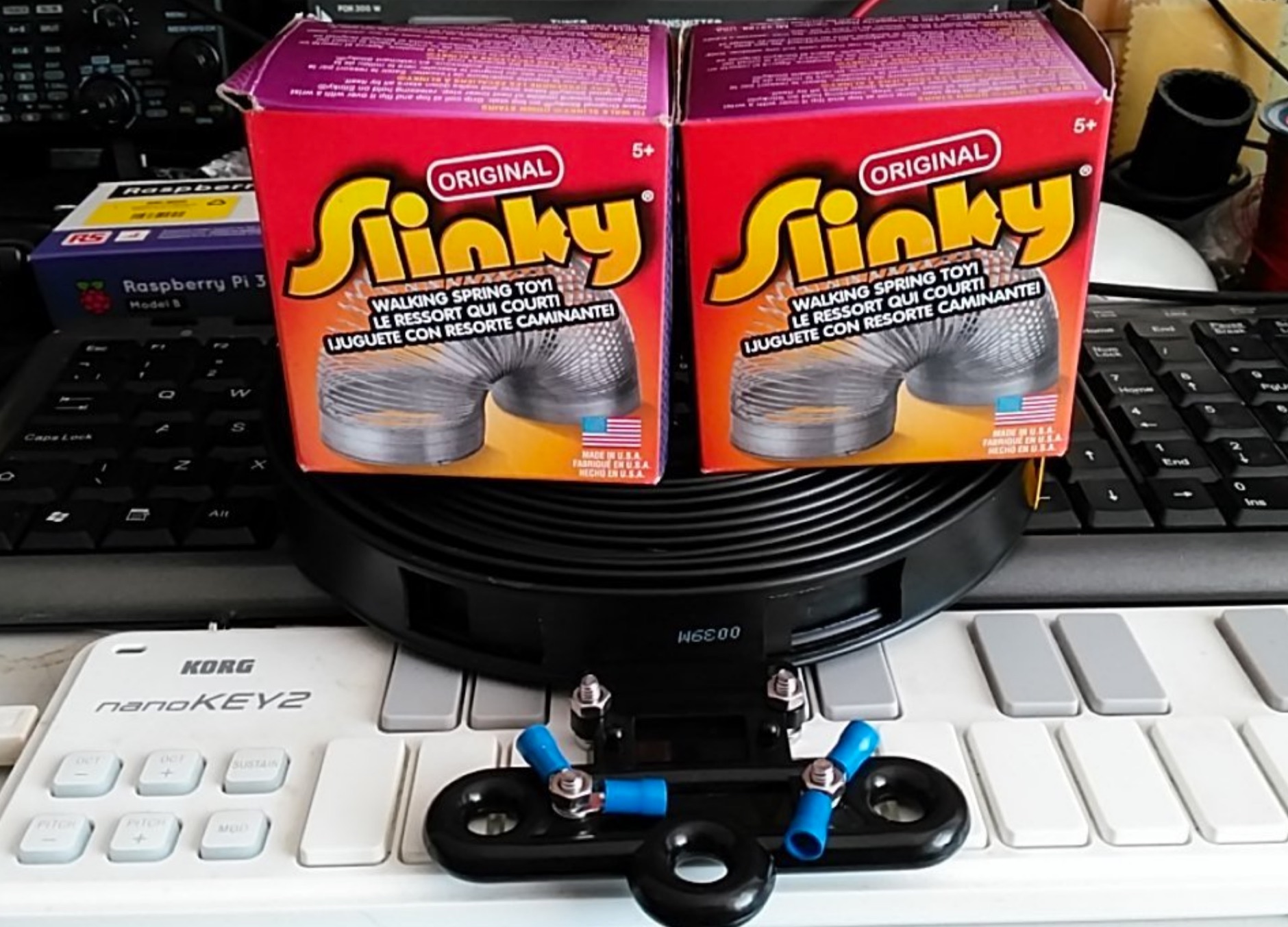 An home made doblet antenna made with two Slinkys that are aproximately five meters in length connected with a twin-feed connected to a balanced ATU
 -
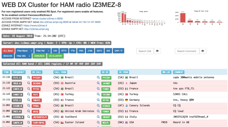 The IZ3MEZ Web DX Cluster presents real-time amateur radio DX spots across 20 distinct frequency bands, spanning from **LF (2190m)** at 135.7 kHz up to **SHF (QO-100)** at 10499 MHz. It displays the DX callsign, frequency, DXCC entity, spotter callsign, and spotter DXCC entity, along with any accompanying comments. The cluster also lists various operating modes such as CW, RTTY, FT8, FT4, FT2, PSK, and SSTV, and supports special operating activities like QRP/P and specific award programs including IOTA, POTA, SOTA, WCA, and JOTA. The cluster's interface provides a dynamic feed of the latest 50 spots, continuously updated with precise timestamps. It offers direct **Telnet protocol** access for users preferring a command-line interface, with configuration instructions provided. The resource also integrates with other spotting networks like RBN and PSK Reporter, enhancing its utility for DXers and contesters seeking propagation information and activity monitoring across a broad spectrum of amateur radio frequencies.
 -
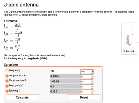 Online calculator for J-Pole antennas. The J-pole antenna consists of a short and a long vertical pole with a feed point near the bottom. The antenna looks like the letter J, hence the name J-pole antenna.
 -
-
 1500 watts PEP SSB is the power handling capability of the MFJ-989C HF Antenna Tuner, a popular choice among amateur radio operators. Users have shared a wide range of experiences, with some praising its durability and performance over decades of use, while others criticize its build quality and accuracy. The tuner features a built-in dummy load, SWR-wattmeter, and a balun for balanced line feeders, making it versatile for various antenna setups. However, discrepancies in RF power readings and SWR measurements have been noted, with some users finding the dual scale meter to be off by about 20% compared to a Bird wattmeter. Long-term users report that the MFJ-989C performs well with proper antenna setups, but caution against tuning at high power without initial adjustments at lower power levels. Some have experienced issues such as arcing when exceeding 400 watts, while others have had no problems even at higher power levels. The roller inductor and capacitors are functional, though some users have had to perform maintenance like tightening screws or cleaning components to ensure reliable operation. Despite mixed reviews, the MFJ-989C remains in production, suggesting continued demand. It's a tuner that requires careful handling and possibly some DIY fixes to achieve optimal performance.
 -
 13cms and 23cms ATV my projects and builds. Also using wifi amps on 13cms, 13cms dish feeds using a Sky dish. GB3CZ
 -
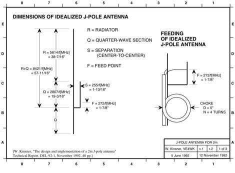 A 144 to 148 MHz J-pole antenna, optimized for base station use, is presented with detailed construction plans. This slim, omnidirectional, half-wave antenna is fed at the end through a quarter-wave shorted transmission line, drawing inspiration from the classic _Zepp antenna_. The design emphasizes achieving a 1:1 VSWR and good efficiency on the 2m band, noting that even a one-percent error in calculation can significantly impact performance. The article provides specific dimensions in inches for the radiator, quarter-wave section, and feed point, along with a parts list for construction from inexpensive materials, estimated at approximately **$10** total cost. The resource offers practical construction tips covering copper pipe selection, L and T joint variations, and detailed soldering instructions using a propane torch. It addresses feedline attachment, the critical role of a four-turn, _5-inch diameter_ choke to prevent coax radiation, and proper antenna fastening techniques, including grounding for lightning protection. The author explicitly advises against scaling the design for other bands due to potential efficiency loss and offers guidance on corrosion protection. The antenna design has been released into the public domain for private amateur use.
 -
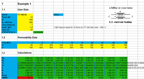 This EXCEL Program Worksheet calculates the common-mode impedance of a 1:1 Guanella (current) balun which is placed at the feed point of a balanced antenna system fed via coax.
 -
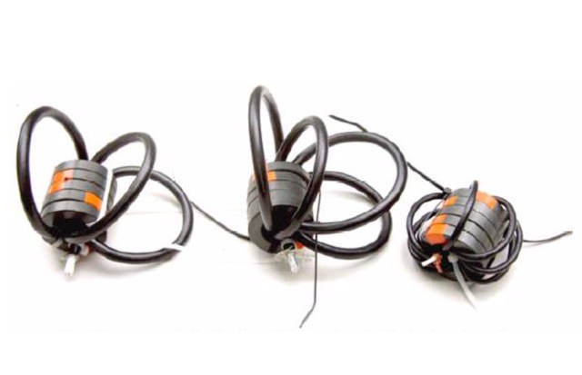 In this article, author examine stresses placed on common-mode chokes (aka baluns) as hams use/abuse them, examine the efficiency of simple dipole multi- band antennas and their feed systems. Stressing a Balun.
 -
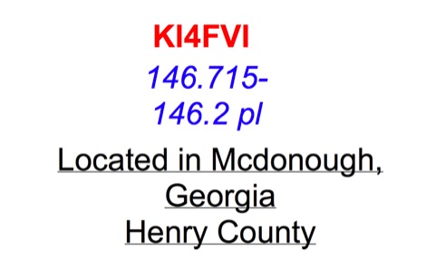 Live Audio Feed of the KI4FVI repeater in henry county Georgia
 -
 Documents the OC1I and OC6I IOTA DXpeditions to Peru, specifically highlighting operations from SA-098 (Isla La Leona) and SA-076 (Isla Lobos de Afuera). The OC1I team logged over **8000 QSOs** from SA-076, while OC6I made 1400 QSOs from SA-098, despite challenging propagation conditions. The resource details the equipment used, including an _IC-7000_, an IC-706mkIIG, and a TS-440SAT, along with various antennas such as a 160m dipole, FD4, G5RV, and a multi-band vertical for 17m, 20m, 30m, and 40m. The DXpedition dates are specified: OC6I operated from SA-098 between December 28 and December 30, while OC1I was active from SA-076 from January 2 to January 7. Both operations are confirmed as valid for IOTA credit. The page also includes a video link for the OC6I operation and a photo gallery from the DXpedition. Feedback is welcomed, and the webmaster is identified as Bodo Fritsche, DL3OCH.
 -
 Listen to online police scanner from Douglas County in Oregon USA
 -
 A private-public partnership with three main goals to collect weather data contributed by citizens; to make these data available for weather services and homeland security; and to provide feedback to the data contributors so that they have the tools to check and improve their data quality
 -
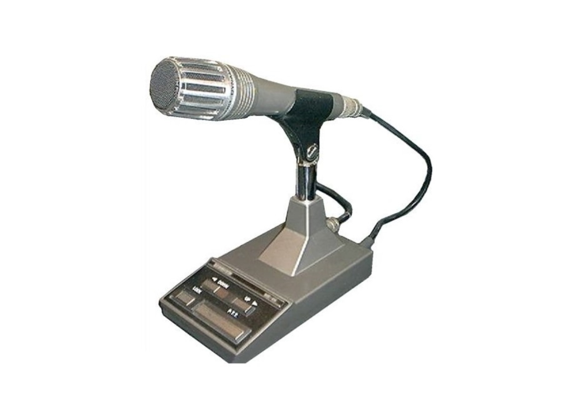 The Kenwood MC60A with preamp, suffers from RF feedback, a search on the web reveals the extent of the problem. This document explain how to fix this problem.
 -