Search results
Query: band
Links: 716 | Categories: 111
This query is too generic. Please try adding an additional term to focus your research.
Categories
- Ham Radio > Band Plans
- Antennas > Multiband
- Operating Modes > Top Band
- DX Resources > Beacons > 10 GHz Beacons
- DX Resources > Beacons > 10 meter beacons
- Antennas > 10M
- Antennas > 17M
- Antennas > 20M > 20 meter Dipole Antennas
- Antennas > 20M > 20 meter Vertical Antennas
- Antennas > 20M > 20 meter Yagi antennas
- Antennas > 20M
- Antennas > 23cm
- Antennas > 2M
- Antennas > 30M
- Antennas > 40M > 40 meter Dipole Antennas
- Antennas > 40M > 40 meter Loop Antennas
- Antennas > 40M > 40 meter Yagi Antennas
- Antennas > 4M
- Antennas > 6M > 6 meter J-Pole Antenna
- Antennas > 6M > 6 meter Moxon Antennas
- Antennas > 60M
- Operating Modes > 70 MHz
- Antennas > 80M
- Radio Scanning > Aeronautical
- Operating Modes > Aircraft scatter
- Radio Equipment > VHF-UHF Handhelds > Baofeng UV-3R
- Technical Reference > Beacon keyers
- Software > Beacon Monitoring
- DX Resources > Beacons
- Technical Reference > Radio Frequency Interference > BPL
-
 This antenna article is geared towards new Hams and antenna builders looking for a very inexpensive 6 band antenna that can be efficiently fed with 50 ohm coax without a tune
 -
-
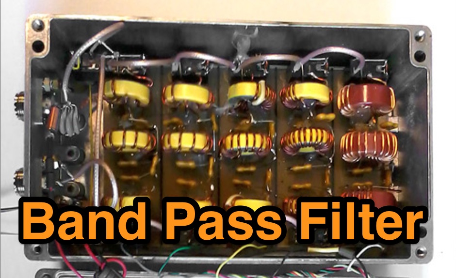 A simple project for an effective home made band pass filter, designed for the portable field day usage
 -
 A nice post on Make: on homebrewing a multiband antenna for amateur radio portable operations
 -
 The ÖVSV website provides extensive resources for Austrian radio amateurs, including details on its nine **Landesverbände** (regional sections) and the Austrian Military Radio Society (AMRS). It features information on licensing, legal frameworks, and **band plans** for both HF and VHF/UHF operations. The site also covers various amateur radio activities such as contests (HF, VHF/Microwave, Alpe-Adria, SOTA, ARDF), technical projects like WRAN, and educational content explaining what amateur radio is and how to become a licensed operator. Recent news items highlight events like the "Laa Funk '26" exhibition, the "OE5XLM" club station's participation in the CQ WW Contest, and the "International Marconi Day 2026" activation by "OE26M" from Küniglberg. The site lists upcoming events, including a 160m OE-Aktivitätsrunde, a seminar on Baluns/Ununs, and various club meetings and flea markets. Membership is facilitated through regional sections, and the site emphasizes amateur radio's role in independent communication during crises.
 -
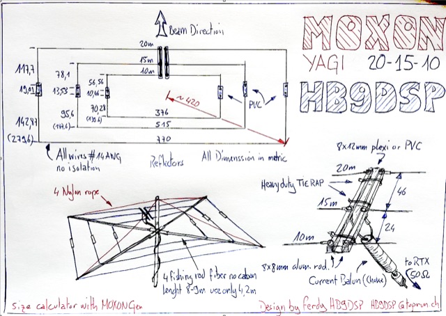 The QRZ.com callsign database serves as a fundamental resource for amateur radio operators worldwide, enabling rapid lookup of station information. Each entry, such as the one for _HB9DSP_, typically includes essential details for making and confirming contacts. Operators can find QSL routes, often indicating preferences like "via bureau or direct," which streamlines the exchange of QSL cards for award credit. Beyond basic contact data, these pages frequently offer insights into an operator's activities, including their participation in contests or DXpeditions. The platform also tracks metrics like "XML Subscriber Lookups," showing how often a callsign's data has been programmatically accessed, totaling **77670** for this specific entry. This functionality is crucial for logging software and other automated systems that rely on accurate, up-to-the-minute amateur radio data. While the page title mentions a "Home made multiband MOXON" antenna, the actual content primarily focuses on the callsign's biographical data within the _QRZ_ database.
 -
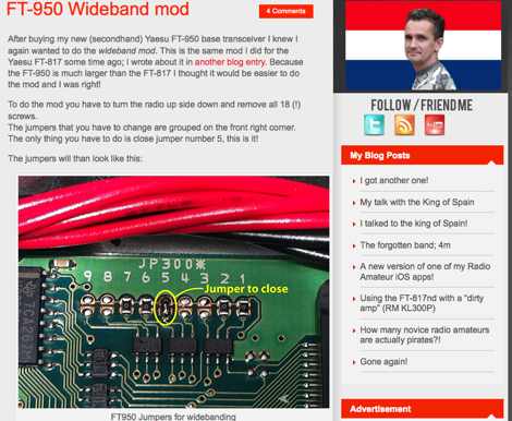 A clear TX wideband mod description for the FT-950. With pictures by PA1CA
 -

-
 Pictures and project design of a crossband VHF UHF repeater by LY3H
 -
-
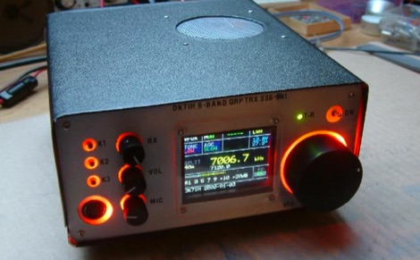 An SSB radio for the HF bands will be presented. Featuring 12 to 20 Watts of output power (depending on DC supply), full DDS frequency generation, covering 6 major frequency bands (1.8, 3.5, 7, 14, 21 and 28 MHz) within the short wave amateur radio spectrum. The rig also features colored LCD and front panel backlight.
 -
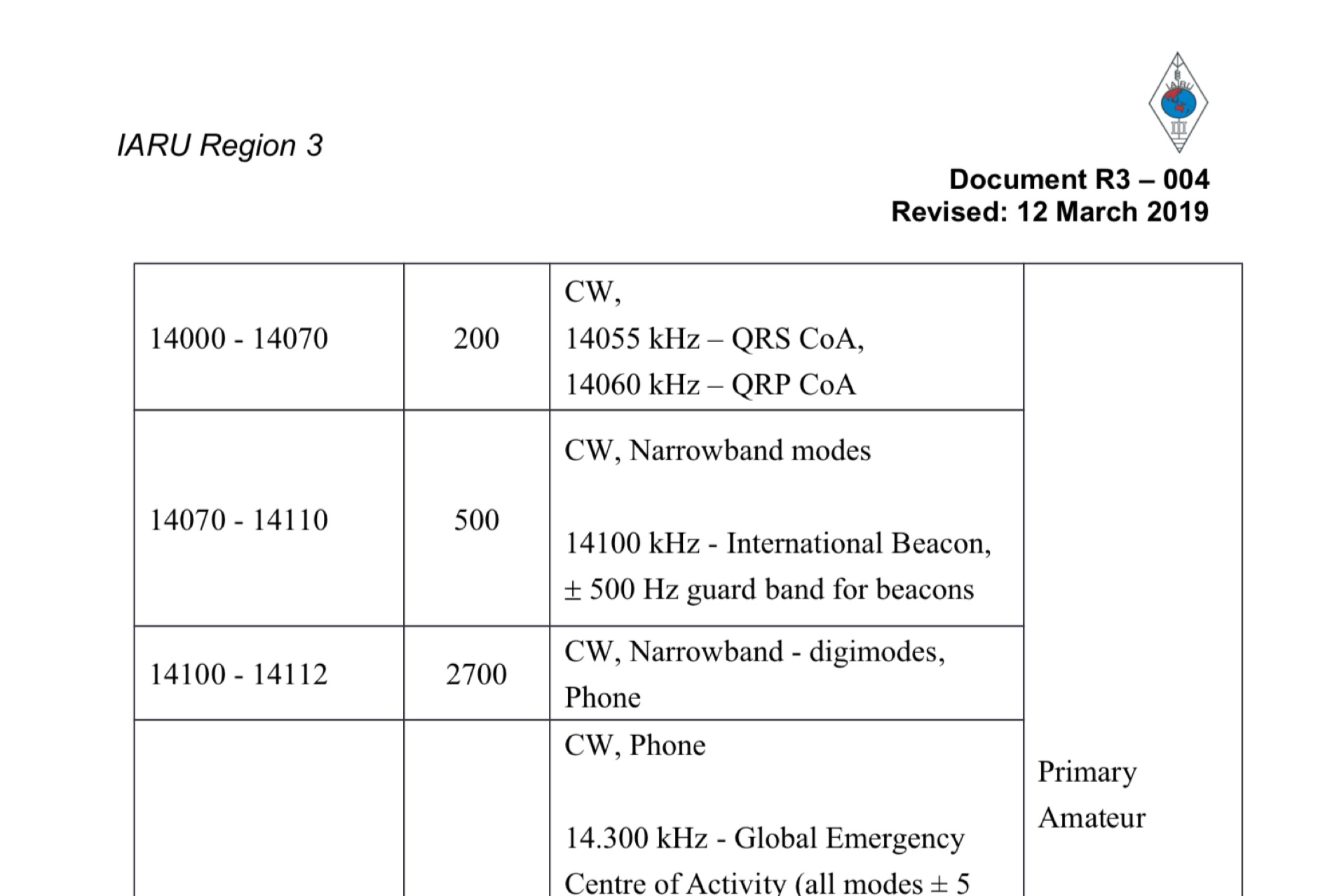 IARU Region 3 bandplan Revised 12 March 2019
 -
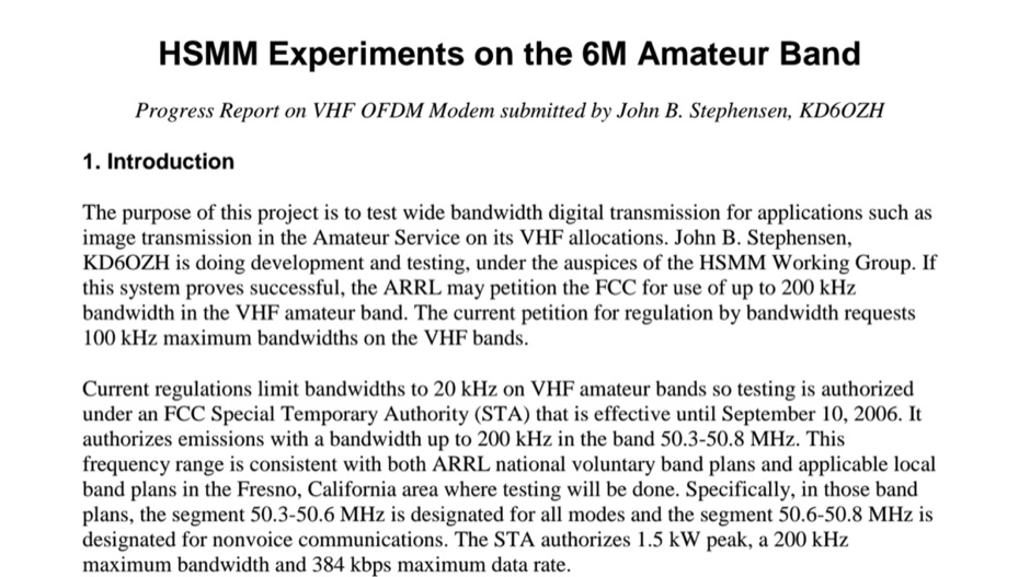
 A 200 kHz bandwidth digital transmission system for image transfer in the Amateur Service is under development, specifically targeting VHF allocations. John B. Stephensen, KD6OZH, leads this project under an FCC Special Temporary Authority (STA) valid until September 10, 2006, authorizing emissions up to 200 kHz bandwidth in the 50.3-50.8 MHz segment. Current regulations typically limit bandwidths to 20 kHz on VHF amateur bands, making this STA crucial for testing wideband digital modes. The modem, a modified **OFDM** (Orthogonal Frequency Division Multiplexed) unit, was initially tested on the 70-cm band. It splits a high-rate data stream into multiple low-rate subcarriers to mitigate multipath echoes. The system uses a DCP-1 card with a Xilinx XC3S400 FPGA and Oki Semiconductor ML67Q5003 microcontroller. The transmitter, located at 36d 46m 30s N, 119d 46m 22s W, generates 150 WPEP into an 8 dBi gain vertical antenna, while the mobile receiver uses a Ham-stick. Three data formats for 50, 100, and 200 kHz channels are being tested, with encoded data rates of 96, 192, and 384 kbps. Verilog code for the VHF OFDM modem is 95% simulated, with modifications from the UHF version including increased filter coefficient precision and a change from Ungerboeck **TCM** to BICM for improved performance over fading paths. Final tests will involve one-way over-the-air measurements of bit error rates and coverage area.
 -
 Modeling compact 160 meter antennas, inverted L, half wave dipoles and linearly loaded dipole
 -
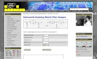 Online calculator, Butterworth Bandstop (Notch) Filter Designer
 -

-
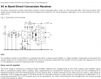 The direct conversion receiver described consists of only a bandpass filter, mixer IC, VFO and audio filter. With only 22 parts, this simple circuit should take a few hours at the weekend to construct.
 -
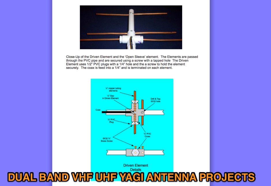 On this page are designs for Dual Band 2M / 70cm antennas. All antennas are 50 ohm designed driver. These Yagis have a unique element called a Open Sleeve. 4 Element 5 element and 9 element Dual Band - 2M / 70cm antenna projects
 -
 22 Different Wire Antennas for the 160 Meter Band, Random Length Radiator Wire, delta loop, loop antennas, off-centered antennas, sloper, dipoles, Z antenna, Zepp and Clothesline Antennas
 -
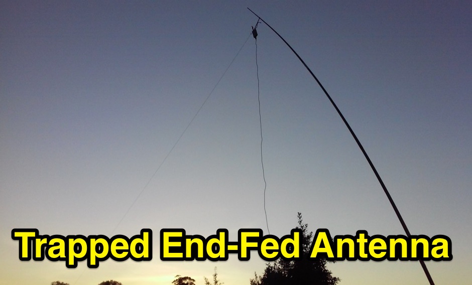 A multiband trapped end-fed antenna can cover 20 30 40m bands. An option for portable sota operations were weight end simplicity are essential
 -
 Demonstrates the construction and tuning of a **20-17-15 meter fan dipole** using 12-gauge PVC insulated copper wire and an Alpha-Delta C kit feedpoint. The project details the use of 14-inch pine dowels with 6-inch spaced holes to maintain wire separation for the parallel elements. Initial tuning was performed at shoulder height, with final adjustments made after elevation to 38 feet, accounting for frequency shifts observed between ground-level and elevated antenna positions. SWR analysis graphs are presented, showing performance below 1:3 across the entire 20-meter band, below 1:2 for 17 meters, and below 1:3 for 15 meters. The author notes significant RX improvements of +3 to +9 dB, occasionally exceeding +20 dB, compared to a commercial Alpha Delta DX LB Plus. The total hardware cost for this DIY antenna project was approximately $90, with the author emphasizing the utility of an **antenna analyzer** like the RigExpert AA54 for precise tuning. The fan dipole also exhibits tunable resonance on 12, 10, and 6 meters, though with reduced efficiency. Performance comparisons on 20 meters showed the fan dipole outperforming the Alpha-Delta on long-path north-south DX contacts.
 -
 Demonstrating the construction of a short dipole antenna tailored for the 60 meter band, this resource provides detailed instructions for radio enthusiasts with limited space. The design incorporates inductive loading using two inductors (L1/L2) made from PVC tubes, allowing for effective operation on 5 MHz. The antenna consists of 12 meters of wire, divided into four sections, with specific dimensions and materials outlined for optimal performance. Results from users indicate that this antenna can significantly enhance DXing capabilities on the 60 meter band. Feedback from operators suggests that while the design is effective, adjustments may be necessary based on individual setups, such as coil diameter and wire gauge. Many users report successful construction and operation, with some experimenting with variations to improve resonance. The practical application of this antenna design has led to successful contacts and improved signal quality, making it a popular choice among 60 meter band operators.
 -

-
 A few thoughts on Multi Band VHF Aerials by Peter Ward VK3ZAV
 -
 An EH Antenna for 14 MHz by EB3EMD based on an original project by F5SWN
 -
 This project is an interface box for the Yaesu FT-817 that includes a band output port, a computer serial interface, and a remote interface for the FL-7000 solid state power amplifiers.
 -
-
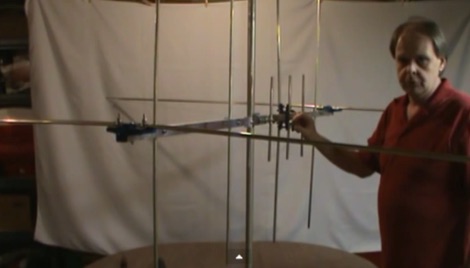 6m/2m/70cm Yagi Antenna Built from Old TV Antenna This turned out to be a great little antenna. It works the 6 meter, 2 meter and 70 centimeter bands. You can use one common feedpoint or two seperate feedpoints depending on how you would like to connect this antenna to your transceiver.
 -
 Design and build a 6 meter 2-element Moxon antenna mostly from available aluminum tubing and angle stock.
 -
 A DIY Automatic Band Decoder (ABD) project, designed for dual-radio operation, addresses the common challenge of integrating band data with older transceivers lacking dedicated outputs. This particular build utilizes an AVR AT90S8515 microcontroller and a 16x2 Liquid Crystal Display (LCD) to provide band information, specifically targeting Kenwood rigs via a computer's LPT port. The design aims for cost-effectiveness while maintaining functionality, offering a solution for hams seeking to add automatic band switching capabilities to their station without significant expense. The project outlines the core components required, including the microcontroller, LCD, and an enclosure, noting that the Printed Circuit Board (PCB) fabrication and AVR programming might present challenges for some builders. It details the input requirements, such as a four-pin input and PTT for each radio, along with a 13.8V DC power supply. The decoder provides 2x6 outputs capable of sinking 500mA, suitable for controlling external devices like antenna switches or filters. Despite the original unit being damaged by a lightning strike in 2004, the author confirms its successful operation prior to the incident and mentions plans for a revised version. The resource includes a schematic in PDF format and images of the finished PCB and assembled unit, demonstrating the practical implementation of the design.
 -
 The Icom AH-4 autotuner operates efficiently across multiple HF bands, providing seamless automatic tuning for antennas from 3.5 MHz to 54 MHz. Its robust design allows for outdoor installation, making it suitable for field operations and fixed stations. The unit interfaces with Icom transceivers via a control cable, enabling automatic band switching and tuning. The AH-4 is capable of handling up to 120 watts of RF power, ensuring compatibility with most amateur radio setups. Its weather-resistant casing and compact form factor make it a versatile choice for operators requiring reliable performance in diverse environments. Field tests demonstrate the AH-4's ability to maintain low SWR across its operational range, enhancing signal quality and transmission efficiency. Compared to manual tuners, the AH-4 offers significant time savings and ease of use, particularly in rapidly changing band conditions. Its integration with Icom radios simplifies operation, eliminating the need for manual adjustments. The autotuner's performance is consistent with other high-end models, providing a cost-effective solution for amateur operators seeking dependable tuning capabilities without sacrificing performance.
 -
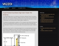
 Optimizing weak signal reception on the HF bands, particularly in the presence of strong local QRM, often necessitates specialized receiving antenna systems. This resource details the _HI-Z Antennas_ product line, focusing on phased vertical arrays designed for superior noise rejection and directivity. It covers components such as the 4-Square and 8-Element array controllers, which allow for rapid switching of receive patterns, and dedicated low-noise preamplifiers to improve system sensitivity. The site also presents various bandpass filters, crucial for mitigating out-of-band interference and enhancing the dynamic range of the receiver. The HI-Z systems are engineered to provide significant front-to-back and side rejection, often yielding **20-30 dB** of attenuation to unwanted signals, which is critical for DXing and contesting. Users can achieve a notable reduction in local noise, allowing for the discernment of signals that would otherwise be buried. The array controllers facilitate quick pattern changes, enabling operators to null out interference or peak weak signals from distant stations, effectively extending the reach of their receive capabilities by improving the signal-to-noise ratio.
 -
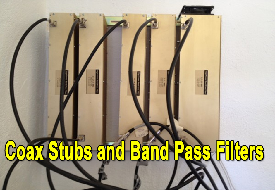 Will additional coax stubs improve Band Pass Filter performance?
 -
-
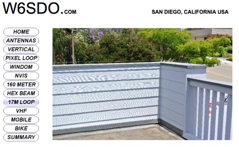 An almost invisible wire antenna for the 17 meters band
 -
 MW0JZE Manufacturer of the G3TXQ Broadband Hexagonal Beam - HexBeam Antennas
 -
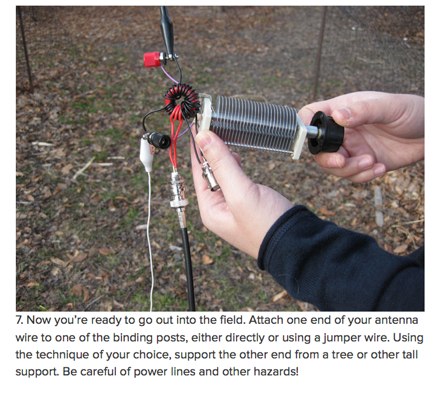
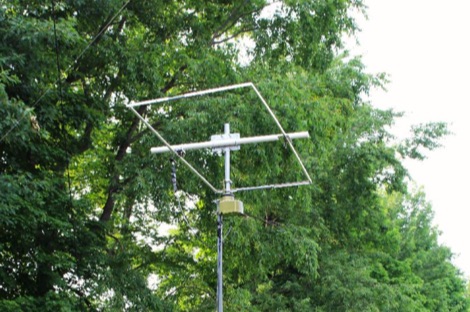
 Demonstrates the swift setup process for a **Trans World Antenna**, showcasing its utility for portable amateur radio operations. The video highlights the antenna's design for quick deployment, a critical factor for activations like Summits On The Air (SOTA) or Parks On The Air (POTA), where efficiency in establishing a station is paramount. It illustrates the physical components and the sequence of assembly, emphasizing ease of use in varied field environments. The antenna system is presented as a multi-band solution, capable of operating across various HF frequencies. This adaptability makes it a versatile choice for hams engaging in outdoor activities or emergency communications. The visual demonstration provides practical insights into managing the antenna elements and feedline for optimal performance during temporary deployments. The focus remains on the practical aspects of field setup, rather than detailed technical specifications or performance metrics.
 -
 Understanding the operational impact of Broadband over Power Line (BPL) on amateur radio communications is crucial for any radio amateur, especially given the potential for significant radio frequency interference (RFI). This ARRL tutorial delves into the technical aspects of BPL, explaining how the technology operates by transmitting data over existing electrical power lines, which can inadvertently radiate broadband noise across various amateur bands. My own field experience, particularly on the lower HF bands, has often involved tracking down noise sources that exhibit characteristics consistent with BPL emissions, making this a pertinent topic for maintaining clear receive conditions. The resource further details the specific FCC rules and regulations implemented to restrict BPL deployment. These regulations aim to protect licensed radio services, including amateur radio, from harmful interference. It outlines the technical standards and operational limitations imposed on BPL systems to minimize their impact on the electromagnetic spectrum, a critical aspect for contesters and DXers alike. For those engaged in RFI mitigation, the tutorial provides a foundational understanding of the regulatory framework that can be leveraged when addressing BPL-related interference issues. It serves as a valuable reference for hams seeking to comprehend the technical challenges and regulatory solutions surrounding this pervasive noise source.
 -
 Performance of an unloaded ground mounted vertical as a multi-band HF antenna.
 -

-
 This resource, a blog from the Penang Amateur Radio Club (PARC), offers insights into various aspects of amateur radio in Malaysia. One post details monitoring Automatic Terminal Information Service (ATIS) on the 2m band, providing specific frequencies like 122.750 MHz AM for Butterworth and 126.400 MHz AM for Penang, along with sample aviation weather and operational data. Another entry critiques the lengthy and costly process of obtaining an amateur radio license in Malaysia, contrasting it with the more streamlined FCC licensing system in the United States, citing a 1-year wait and RM 414 (USD 125) for 10 years in Malaysia versus 3 weeks and USD 14 for 10 years in the US. The blog also covers internal club matters, such as the 2007 Annual General Meeting (AGM) attendance and council elections, highlighting member dissatisfaction with outdated newsletters and a call for "reformasi." Additionally, it presents local phonetic alphabets in Bahasa Malaysia and Chinese, and discusses monitoring AM broadcast bands for international stations like Voice of America on 1575 kHz and Zhong Yang Ren Min Guang Bo Dian Tai on 1134 kHz, offering alternatives to local 2m repeater chatter. The author, "firstclass," shares personal observations and criticisms regarding the Malaysian ham radio landscape.
 -
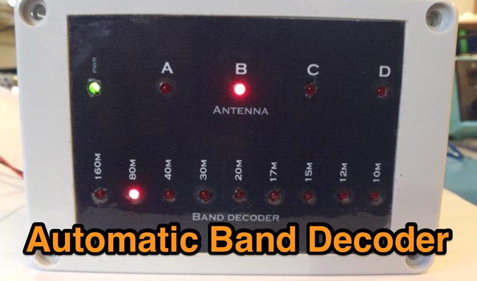 An automatic band decoder made into a nice enclosure with LED indicators for the chosen band
 -
 The page provides detailed instructions on how to build a 60 meter End Fed Half Wave Antenna Tuner, with large pictures and diagrams. It is aimed at amateur radio operators looking to construct their own antennas for the 60 meter band.
 -
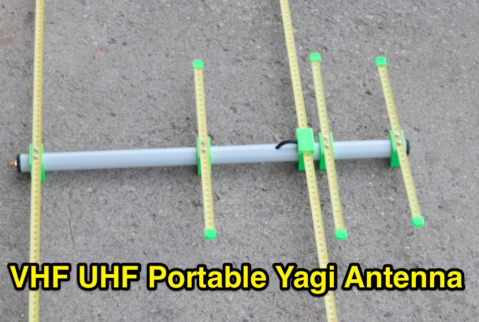 Tape measurement yagi. The longest part is 530 mm, easy fit to your backpack. Very easy and fast deploy. Great for SOTA and portable operation. Can be used in horizontal or vertical polarization. Based on DK7ZB design
 -
 An easy to build dipole for 21 and 14 MHz with traps made by two T50-6 toroids cores mounted on a simple PCB foil
 -
 The TransWorld Antennas TW4040 The Adventurer Monobander™ is a portable HF antenna designed for rapid deployment in field operations, including **SOTA** and **POTA** activations. This manual details the antenna's assembly, tuning procedures, and operational guidelines for optimal performance on the 40-meter band. It outlines the specific components, such as the telescoping whip and base unit, required for proper setup. Instructions cover mast erection, radial wire deployment, and impedance matching to achieve a low **VSWR** across the designated frequency segment. The document also provides guidance on antenna orientation and environmental considerations for portable use. It specifies the antenna's power handling capabilities and physical dimensions when fully deployed and collapsed for transport.
 -
 Changing band selector to a Kenwood TL-922 power amplifier by IW1PUR in italian
 -
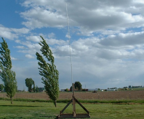 Homebrew 30 meter full quarter wave vertical antenna.
 -
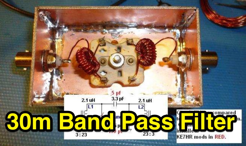 A homemade band pass filter for the 30 meter band based on the original VE7BPO design
 -
 A 600W 1.8 MHz to 54 MHz power linear amplifier made using rugged MRF300 transistors featuring output power between 580W and 750W depending on band, power supply: 48V, 18A typical, 20A max