Search results
Query: construction details
Links: 198 | Categories: 8
-
 Demonstrates the construction of a **multi-band HF mobile antenna** utilizing a modified CB whip antenna base. The resource details the process of stripping a commercial CB whip, winding a new helical coil with 0.7mm insulated copper wire, and identifying tapping points for various HF bands. It emphasizes the importance of a rugged, slim design for mobile operation, discussing mechanical length, power handling (up to 200 watts), and coil diameter considerations. The article includes a graphic illustrating the antenna's operational principle, where sections of the helical coil are shorted from bottom to top to maintain efficiency and high Q. The resource presents a practical approach to achieving **band switching** without an external tuner, by manually adjusting tapping points on the coil. It provides a table with reference lengths in centimeters from the feedpoint for 7 MHz (40m) through 28.7 MHz (10m), including WARC bands. The author details mounting techniques, suggesting a Diamond bracket for secure attachment to a vehicle trunk, and stresses the critical role of proper grounding for optimal performance. The design allows for operation on 75m and 80m bands by adding a 110mm steel whip.
 -
 This resource provides a detailed guide on constructing a J-pole antenna specifically for the 2 meter band, which is popular among amateur radio operators. The article outlines the materials needed, including various sizes of aluminum pipes and PVC, as well as the tools required for assembly. It emphasizes the simplicity and effectiveness of the J-pole design, making it an ideal choice for newcomers to amateur radio. The instructions are straightforward, allowing users to build the antenna in less than an hour, and include tips for tuning the antenna for optimal performance. In addition to the construction details, the resource includes practical advice on the assembly process, such as how to cut and join the pipes, as well as how to mount the SO239 connector. The author shares personal experiences and insights on achieving a low standing wave ratio (S.W.R.) and suggests modifications for creating bi-band or tri-band J-pole antennas. This comprehensive guide is enriched with photographs that illustrate the construction steps, making it easier for users to follow along and successfully build their own J-pole antenna.
 -
 This resource provides comprehensive instructions for constructing a 2 element quad antenna specifically designed for the 10, 12, and 15 meter bands. The antenna features a diamond configuration, which offers improved gain compared to a square configuration. The author shares insights into the materials used, including a square-aluminum boom and bamboo poles, along with construction techniques that ensure durability and optimal performance. This project is ideal for amateur radio enthusiasts looking to create their own antennas at home. In addition to construction details, the author discusses the antenna's performance, noting its effectiveness even at a height of 8 meters. The quad antenna reportedly performs comparably to a 3 element yagi, with excellent SWR readings and strong signal reports from European stations. This project is suitable for beginners and offers a cost-effective solution for those interested in enhancing their amateur radio setup with a homemade antenna.
 -
 An effective 10-20m DX antenna for deed restricted lots. The article by K7ZB introduces a simple 10-20m DX antenna suitable for deed-restricted lots. The antenna, a 15' vertical design, facilitated contacts with over 200 countries worldwide. Its design employs a telescopic aluminum tube and radial wires for multi-band operation, requiring an external antenna tuner for optimal performance. The mounting scheme and construction details ensure effectiveness and ease of use.
 -
 Dissects the internal components of the popular _Antron 99_ vertical antenna, revealing its unique design elements. The analysis details the construction of the coaxial phasing sections, which contribute to its multi-band performance across 10, 12, 15, and 17 meters. Observations include the use of fiberglass tubing for weather protection and the specific arrangement of conductors within the antenna's structure. The examination highlights the antenna's reliance on a series of coaxial stubs to achieve resonance on multiple HF bands without external tuning. This internal architecture provides insights into how the _Antron 99_ manages impedance matching and radiation patterns for effective DX operation. Further details cover the antenna's base mounting and overall physical dimensions.
 -
 Details the construction of a **multiband vertical** antenna, specifically designed for stealth operation in a rented property, covering 80m, 60m, 40m, and 30m. The author, N3OX, leverages a 12m Spiderbeam telescoping fiberglass pole as the primary support, noting its sturdiness compared to typical fishing rods while remaining light enough for quick deployment and takedown. The radiating element is a 14 gauge Flex-Weave wire, attached to the pole's top with a rubber grommet, and fed by 27 bare 18 gauge radials spread across a 40-foot square backyard. N3OX describes the impedance matching solution, opting for custom-built L-networks over a remote tuner to enable fast bandswitching. Using an MFJ-259B and EZNEC modeling, base impedances were measured and component values calculated with G4FGQ's L_TUNER and SOLNOID_3 programs. The 80m coil is wound on a 3.5-inch PVC form, while the 30m, 40m, and 60m coils are air-wound, self-supporting #10 wire. Variable capacitors are incorporated for 40m and 30m shunt elements, with the 60m impedance matched by a series inductor. The project includes a **servo-controlled** homebrew band switch, utilizing a two-pole 12-position ceramic wafer switch for remote operation, addressing the limited 80m bandwidth. The entire matching network is housed in a weather-resistant shelter constructed from lumber and aluminum flashing. N3OX reports good DX results at 100W, estimating the total cost between $150 and $250, depending on existing parts.
 -
 This resource details the fundamental aspects of deploying longwire antennas, emphasizing ease of construction and installation for shortwave listening (SWL) and broadcast reception. It covers wire gauge selection, suggesting 14 to 24 AWG for general use, with heavier gauges (14-20 AWG) for permanent outdoor installations. Guidance is provided for various deployment scenarios, including indoor setups where the wire can be run around a room, temporary outdoor installations from balconies using light 18-24 AWG wire, and permanent outdoor configurations requiring higher placement and slack for tree movement. Feeding methods are discussed, recommending coaxial cable (50-75 ohms) to mitigate man-made interference, with instructions for connecting only the center conductor to the longwire. Safety precautions are highlighted, particularly avoiding contact with power lines and conductive materials, and managing static electricity buildup by unplugging the antenna after use and bleeding off charges before connection. The article also advises against using outdoor longwires during thunderstorms or snowstorms due to static and lightning risks. Optimal height considerations are presented, advocating for the highest safe placement, ideally a couple of feet above underlying structures, to maintain free air space. The text mentions a personal setup with one end at a roof peak (20 feet) and the other at a 17-foot mast, illustrating practical deployment without strict height requirements beyond safety and clearance.
 -
 This PDF article from April 2001 QST details the construction of the "NJQRP Squirt," a reduced-size 80-meter inverted-V dipole antenna. The resource provides a general construction sketch, a photograph of the assembled antenna, and specific dimensions for PC-board insulators. The antenna consists of two wire legs, each approximately **34 feet long**, separated by 90 degrees, fed at the center. It is designed for operation on 80 meters (3.5-4.0 MHz) as a quarter-wavelength antenna, requiring a low-loss feedline and an external antenna tuner due to its non-resonant feedpoint impedance. Construction utilizes readily available materials, including 1/16-inch glass-epoxy PC board for end and center insulators, and #20 or #22 insulated hookup wire for the elements. The feedline specified is 300-ohm TV flat ribbon line, with a note on potential trimming for tuner compatibility. N2CX reports the antenna's center should be elevated to at least **20 feet**, with ends no lower than seven feet above ground, resulting in a ground footprint of approximately 50 feet wide. The design prioritizes NVIS propagation for local 80-meter contacts. DXZone Focus: PDF Article | 80m Inverted-V Dipole | Construction Notes | 34 ft element length
 -
 For radio amateurs considering homebrew antenna projects, this resource details several designs from WE6W, an experienced operator. It covers the construction and characteristics of a _160 Meter QRP Loop Antenna_ optimized for high voltage, along with standard and folded variations of the double bazooka antenna. The site also presents a unique Field Day antenna design and instructions for building a Sterba Curtain, a directional array known for its gain. Each design includes practical insights from the author's building experience. The author provides comparative data, such as the performance of a standard bazooka against a traditional dipole, offering real-world context for antenna selection. The Sterba Curtain section includes notes on its beamwidth and gain, crucial parameters for directional operation. These designs are suitable for hams looking to experiment with cost-effective, high-performance antennas for various bands and operating scenarios, from QRP on 160m to directional DXing with a Sterba Curtain, which can offer significant forward gain, often exceeding **10 dB**.
 -
 Details the construction of a J-vertical antenna specifically for the 10-meter band, offering a practical alternative to a _Slim Jim_ design for 28 MHz. The resource outlines the use of aluminum tubing for the half-wave vertical section and coaxial cable for the quarter-wave matching section, providing specific calculations for element lengths based on frequency and coaxial cable velocity factor. It contrasts the performance of the J-vertical with center-fed dipoles and end-fed verticals, noting superior results in previous comparisons. The article further presents a more recent iteration of the J-vertical, constructed using a fiberglass pole and insulated wire, with updated dimensions for 28.8 MHz. It includes practical advice on weatherproofing connections and securing the antenna for durability against adverse conditions, referencing the survival of an original _J Vertical_ during 110 MPH winds in 1987. The SWR performance is reported as 1.1:1 at 28.6 MHz, maintaining below 1.5:1 across 28.3 to 29 MHz.
 -
 EH antenna for 160 mt: my experiment and comparison with a short vertical. with full details on construction procedure and testing.
 -
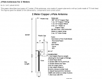 The page describes two types of 2 meter J-Pole antennas, one made of copper pipe and a roll-up J-pole made of TV twin lead, providing dimensions, components, and construction details. It is authored by Dr. Carl O. Jelinek N6VNG.
 -
 The RXO Unitenna, a vertical wideband antenna, offers operation across the 7-21 MHz spectrum, covering the 40, 30, 20, 17, and 15-meter amateur bands. This design focuses on achieving a low SWR across a broad frequency range, making it suitable for general HF operation without requiring an external antenna tuner for minor SWR variations. The antenna utilizes a unique loading coil and matching network to maintain efficient radiation characteristics across its operational bandwidth. Construction details within the PDF document include specific dimensions for the radiating element and the counterpoise system, which is critical for vertical antenna performance. The design incorporates readily available materials, simplifying the build process for radio amateurs. Performance graphs illustrate the SWR characteristics across the 7 MHz to 21 MHz range, demonstrating the antenna's wideband capabilities. The document also provides guidance on feedline connection and grounding considerations for optimal field deployment. This vertical antenna configuration is particularly useful for hams with limited space, offering a compact footprint compared to horizontal wire antennas.
 -
 The project details a DIY SWR/Wattmeter designed around an _Arduino Uno_ shield, providing capabilities to measure RF power from 2 to **200 watts** and Standing Wave Ratio (SWR) for HF amateur radio bands. This construction features a compact design, integrating the measurement circuitry directly onto a custom PCB that interfaces with the Arduino Uno microcontroller. Key components include a directional coupler for sensing forward and reflected power, precision rectifiers, and analog-to-digital conversion for processing RF signals. The Arduino firmware handles calibration, calculations, and displays the results on an integrated LCD, offering real-time feedback on antenna system performance. The design prioritizes simplicity for homebrewers. Performance specifications indicate accurate readings within the **2-200W** power range, suitable for typical QRP to medium-power HF operations. The project provides schematics and a basic overview of the software logic.
 -
 This page details the construction of an easy-to-make collinear 360 degrees omni-directional, vertically polarised, antenna for 802.11b/g wireless networking.
 -
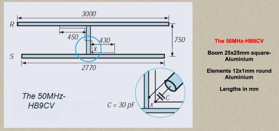 The HB9CV-Beam is a 2-Element-Yagi with two driven elements and was introduced by Rudolf Baumgartner, HB9CV in the 1950ies. This beam antenna is a coax-feeded version of the ZL-Special construction by DK7ZB for 2m, 6m and 10m
 -
 Details the construction and optimization of antenna systems for amateur radio satellite operations, focusing on practical, homebrew solutions for VHF/UHF bands. It covers building _groundplane antennas_ from salvaged materials, recycling old beam antennas into new configurations like a 2-meter crossed yagi, and constructing a 10-meter horizontal delta loop. The resource also explains antenna matching techniques, including folded dipole driven elements and quarter-wave transformers, along with the importance of accurate SWR measurements and minimizing coax loss. Demonstrates how to achieve a **1:1 SWR** by carefully trimming elements and adjusting radial angles on groundplane antennas. It provides insights into selecting appropriate coax and connectors, highlighting the benefits of Belden 9913 for low loss and the proper installation of _N-connectors_. The article also addresses RFI mitigation from computer birdies and presents a design for a silent triac antenna control circuit, offering practical solutions for common satellite station challenges.
 -
 Presents a practical design for a **crossed-dipole turnstile antenna** specifically engineered for 2-meter Amateur Radio Direction Finding (ARDF) events. The author, WB6RDV, details a robust, omnidirectional, horizontally-polarized antenna, addressing the international ARDF rules requiring such characteristics at a height of two to three meters above ground. This contrasts with the vertical polarization often used in Southern California, highlighting the design's adherence to specific event requirements. The electrical design employs a classic crossed-dipole with a 75-ohm phasing section, resulting in a slight impedance mismatch and an SWR of approximately 1.3:1 with a 50-ohm feedline. Construction utilizes readily available and inexpensive PVC plumbing components and 1/8-inch bronze welding rod for elements. The guide provides step-by-step instructions for mechanical assembly, including drilling element holes at precise 90-degree spacing and preparing the RG-179 matching section. WB6RDV shares insights from his own build experience, discussing the use of plated brass versus aluminum spacers for element attachment and the effectiveness of crimping as an alternative to soldering. The document also covers final assembly, including the integration of ferrite beads as a choke balun and options for weatherproofing and alternative mounting configurations, emphasizing the adaptability of the design for other VHF bands through scaling.
 -
 This resource, last modified in August 2000, provides a personal amateur radio web presence for N3LS Larry, focusing on homebrew project announcements and a curated list of amateur radio links. It mentions plans for 10 to 15 new homebrew projects, indicating a focus on DIY electronics construction. The page also offers guidance for aspiring amateur radio operators, including tips for obtaining study guides and links to testing practice sites, suggesting an educational component for newcomers to the hobby. The content primarily serves as a personal hub, with a strong emphasis on sharing homebrew endeavors and supporting new licensees. While specific project details are not present, the intent to add numerous homebrew projects highlights a practical application of electronics knowledge. The inclusion of study resources aims to assist individuals in preparing for amateur radio license examinations, making it relevant for those seeking to enter the hobby.
 -
 Presents a collection of homebrew amateur radio projects and circuit ideas developed by EA5/G3PTO, a licensed operator since 1961. The resource details various transmitters and receivers constructed for frequencies ranging from 1.8 MHz to 10 GHz, emphasizing CW and BPSK31 operation. Specific projects covered include a "Bombproof 7Mhz Receiver" and several keying circuits, providing insights into designs that have proven effective over decades of use. The site also integrates personal photography, showcasing scenes from the West of England and Southeast Spain, reflecting the author's interest in connecting with other amateurs and visualizing their locations. Additionally, it offers a curated list of links to other home construction sites and DX information, serving as a hub for DIY enthusiasts and DXers. The content is distinctively personal, blending technical project documentation with a broader view of the amateur radio lifestyle and community engagement.
 -
 Demonstrates the construction of a **remote antenna tuner** utilizing a standard radio-controlled (RC) servo mechanism to adjust a variable capacitor. The design focuses on enabling remote tuning for narrow-bandwidth antennas, specifically mentioning frame and packing crate antennas, from within the shack. It covers the mechanical arrangement for integrating the servo with a capacitor and provides a circuit diagram for a control unit that generates the necessary 0.5mS to 1.5mS pulse-width modulation (PWM) signals to drive the servo's 180-degree rotation. This setup was successfully tested with up to 20 watts RF power without arcing or adverse effects on the servo, though tuning was performed at 1 watt for VSWR readings. The resource highlights the use of inexpensive, readily available components, such as Futaba servos, and details critical considerations like power supply decoupling with a 47uF capacitor to prevent unintended servo movement upon power-off. The system provides a practical solution for optimizing antenna performance for specific frequencies without manual adjustment at the antenna itself.
 -
 50 MHz 1500 Watt Russian GS35B amplifier. Well documented. Complete construction details,pictures,schematics, and more.
 -
 The Flower Pot Antenna project details a portable dual-band antenna primarily operating on 10 meters, with secondary resonance near the 30-meter band. Construction involves winding RG58 coaxial cable uniformly around a large plastic flower pot, approximately 70cm high with a 60cm top diameter. The design eliminates the need for radials, contributing to its compact and lightweight nature. Key construction steps include soldering the inner conductor to the shield at one end of the wound cable and connecting the wound cable's shield to the rig cable's inner conductor at the base. An LC network, comprising a variable capacitor (0-200pF) and an inductor (10 coils, 5cm diameter, 2mm wire), is inserted between the wound cable's inner conductor and the rig cable's shield. Tuning is performed with an antenna analyzer, adjusting cable length and the variable capacitor for optimal impedance on 10 meters. The antenna performs effectively when installed horizontally.
 -
 Over 30 distinct shortwave (SW) receiver models are reviewed, offering insights into their performance, features, and user experiences. These evaluations, contributed by readers of the Usenet newsgroup **Rec.radio.shortwave**, cover a wide array of portable and tabletop radios, including popular units like the Grundig YB-400, Sony ICF-SW77, and various Realistic DX series models. Each review details aspects such as frequency range, tuning steps, SSB functionality, antenna performance, and construction quality, often comparing them to other receivers or ham transceivers like the Icom 725. For instance, the Grundig YB-400 review highlights its 144-30000 kHz AM/SSB coverage, direct keypad entry, and 40 station memories, noting its useful narrow bandwidth and tone switch for adjacent signal separation. It also discusses the **SSB mode** stability and the limitations of its 1 kHz frequency resolution for precise zero-beating. The review further details antenna performance, including the effectiveness of the built-in whip, the provided 7m reel antenna, and the potential for overload with larger outdoor antennas. Other reviews delve into specific issues, such as the Sony ICF-SW77's frequency display inaccuracies and timer malfunctions, or the Realistic DX-342's compact size and surprisingly good MW DXing capabilities despite its analog tuning. The collection provides practical, user-generated feedback on sensitivity, selectivity, audio quality, and ergonomic features, helping shortwave listeners understand the real-world performance and quirks of these receivers.
 -
 Demonstrates the construction and on-air performance of the _NB6Zep_ antenna, a modified 20-meter Extended Double Zepp design optimized for multi-band operation from 40 through 10 meters. The resource covers basic design principles, including dimensions of 66 feet horizontal and 5 feet vertical elements, and specifies open ladder line or TV twin lead for the transmission line. It details material selection for low-cost wire antenna construction, such as 18 AWG wire for the legs and ceramic or plastic insulators, along with practical tips for soldering connections and insulating against moisture. The author, NB6Z, shares insights from extensive _EZNEC_ modeling to optimize the antenna's total length for a 40-meter half-wave dipole footprint and feed line length for direct tuner connection. The article presents field results, including successful _PSK31_ contacts from Oregon to the East Coast on 40 and 30 meters with 50 watts, even at a low height of 6 feet. It provides detailed performance characteristics for each band, noting the _NB6Zep_'s highest gain (over 3 dB) and sharp, medium-angle lobes on 20 meters, which yielded strong DX reports to locations like Korea, Japan, and Argentina. For 17 and 15 meters, it describes a butterfly-like pattern with broad lobes, while 12 and 10 meters exhibit narrow, directional lobes in an "X" configuration. The author also shares personal experiences operating successfully for over a decade in an antenna-restricted environment using the NB6Zep and other stealth wire antennas.
 -
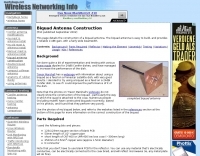 This page details the construction of a biquad antenna. The biquad antenna is easy to build, and provides a reliable 11dBi gain, with a fairly wide beamwidth.
 -
 Presents a catalog of **QRP** transceivers, antenna tuners, and related accessories for amateur radio operators. The product line includes the ZM-2 antenna tuner, designed for efficient impedance matching across HF bands, and the NW-series QRP transceivers, offering low-power CW operation. Additionally, the site details various ladder line insulators and specialized connectors, emphasizing robust construction for field deployment and home station use. Each product listing provides specifications, operational parameters, and pricing information. Compares the features of different **QRP transceiver** models, such as the NW-40 and NW-20, highlighting their respective band coverage and power output capabilities. The ZM-2 tuner's performance is detailed with typical SWR reduction figures for various antenna types, demonstrating its utility for portable and fixed stations. Customer testimonials and product images illustrate the practical application and build quality of EMTECH's offerings, providing insights into their durability and ease of integration into existing amateur radio setups.
 -
 A 144 MHz kilowatt amplifier project details the construction and performance of a high-power VHF linear using the GU74b tetrode. This Russian tube, equivalent to the Svetlana 4CX800, is noted for its conservative datasheet ratings, performing closer to 800-1000W anode dissipation in practical applications. The design prioritizes compactness and achieves 1.2 kW output with only 20W of drive power, demonstrating a 70% efficiency at 2.5 kV plate voltage. The amplifier has been successfully deployed in demanding _EME_ (Earth-Moon-Earth) operations since June 1994. Challenges encountered during development included achieving stability with a grid-1 input configuration. The author, _CT1DMK_, opted not to publish the full design due to its complexity, suggesting it might be difficult for less experienced builders to replicate successfully. However, he invites direct contact for those with specific interest in the design. Future plans include a "144MHz GS35b compact amplifier" project, promising another kilowatt-plus design. This resource offers insights into high-power VHF amplifier construction and the practical application of specific power tubes.
 -
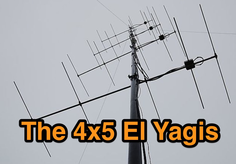 2m SSB/CW-12.5 Ohm Yagis with extrem high gain and small bandwidth. These Yagis were constructed as ultra-light, portable Yagis with extrem high gain. They have small bandwidth and are working from 144,0-144,8MHz with good SWR.
 -
 Demonstrates the construction and performance of an updated ZS6BKW multiband dipole, a variant of the _G5RV_ antenna, specifically designed for HF operation. The article details a real-world installation using 13.5m copper wire elements and 12.2m of 450 Ohm ladder line, configured as a sloping inverted-V with the apex at 10m and ends at 4m above ground. It covers the critical aspect of impedance matching, incorporating an 8-turn choke balun at the feedline transition to RG-58U coax to mitigate RF common mode current. Measurements confirm favorable SWR readings below **1.3:1** on 7.1 MHz, 14.11 MHz, 18.06 MHz, and 24.8 MHz, indicating effective resonance across 40m, 20m, 17m, and 12m bands. The installation also shows usable SWR dips on 3.55 MHz (5:1), 29.02 MHz (2:1), and 50.84 MHz (3:1), extending its utility to 80m, 10m, and 6m with an antenna tuning unit. Initial on-air results report clear reception of stations over **5000km** away, validating its DX potential.
 -
 Indoor multiband dipole with EZNEC data files for simulation and analysis. Includes details on construction, tuning, SWR plots, and software usage. This page includes two different dipoles, a first version for 20-10 meters and an extended version covering 40-10 meters allowing a full coverage of most used ham radio HF Bands.
 -
 One common challenge in antenna systems is mitigating common-mode current on the feedline, which can distort radiation patterns and introduce RF in the shack. This project details a 1:1 balun design that ingeniously avoids traditional ferrite beads, often a costly component, by substituting them with steel wool. The steel wool, when integrated into the balun's construction, effectively attenuates unwanted RF on the outer braid of the coaxial cable, ensuring that the antenna radiates efficiently and as intended. The construction involves winding coaxial cable through a PVC former, with the steel wool strategically placed to provide the necessary common-mode impedance. This method offers a practical and economical alternative for hams looking to build effective baluns without the expense or availability issues associated with ferrite cores. The design principles focus on creating a balanced feed to the antenna, crucial for optimal performance of dipoles and other balanced radiators. Experimentation with such designs can lead to improved field results, particularly for those operating with limited budgets or seeking innovative solutions for their antenna systems. The simplicity of using readily available materials like steel wool makes this a compelling build for many radio amateurs.
 -
 The Petlowany Three-Band Burner is a simple, low-cost, trapless short vertical antenna which amazingly works on three HF bands (20, 15 and 10 meters). This web page contains pictures, performance data, and enough construction details so you can homebrew your own.
 -
 Over 45 years of amateur radio experience inform the homebrew projects detailed on this personal website, with a particular focus on microwave frequencies. The site showcases a 24 GHz transverter and a more recent 47 GHz transverter, demonstrating practical construction techniques for extreme high-frequency operation. These projects often involve custom circuit design and careful component selection to achieve stable performance at millimeter-wave bands. Key projects include a _harmonic converter_ for frequency measurement and a tracking spectrum analyzer, essential tools for microwave experimenters. The site also documents a CW sidetone generator and a TX/RX sequencer, illustrating fundamental building blocks for radio equipment. Details on a digital frequency meter and an S-meter/dBm meter provide insights into test equipment construction. Specific achievements, such as a **24 GHz** tropo QSO with DK3SE in 2021, highlight the operational success of these homebrewed systems. The content reflects a long-standing dedication to self-sufficiency in amateur radio, providing practical examples for those interested in building their own gear.
 -
 Picture and construction details of a 5 element 20 meter monobander
 -
 HA2NON W3DZZ antenna project with pictures and construction details
 -
 The BV6 50 MHz Yagis resource details the construction of two distinct Yagi antenna designs for the 6-meter band, specifically a 1-wavelength (1wl) model and a 2.1-wavelength (2.1wl) model. The 1wl Yagi, with a boom length of 5.850m, achieves a gain of **9.4 dBd**, while the 2.1wl Yagi, spanning 12.90m, boasts a gain of **11.9 dBd**. These designs adhere to a proven methodology for optimizing current slope and maintaining constant phase delay across parasitic elements, ensuring high gain per boom length and an _excellent pattern_. Both designs target a 50-ohm input impedance, facilitating straightforward feeding with a robust folded dipole. Final verification using NEC-II software confirmed the antennas' exceptional stacking capabilities, yielding stacking gains exceeding **5.8 dB** for a 2x2 array with minimal mutual detuning. The resource provides common mechanical data, including boom and element diameters, and specifies element lengths corrected for boom diameter. While the original _DUBUS Technik V_ publication contained incorrect element lengths, this resource provides the accurate dimensions for proper construction, emphasizing the use of readily available materials for cost-effective amateur radio deployment.
 -
 Constructing a high-power solid-state amplifier for HF operations presents unique challenges, particularly when aiming for significant output like 600 watts. This project details an amplifier design employing **Motorola MRF150** FETs, a common choice for their robust performance in RF power applications. The design emphasizes achieving substantial power output, a critical factor for effective DXing and contesting, where every decibel can make a difference in signal propagation and readability. While specific circuit diagrams or construction details are not directly presented on the current page, the mention of MRF150 FETs points towards a design that would typically involve push-pull configurations, impedance matching networks, and robust power supply considerations to handle the high current demands. Such amplifiers are often built with an eye towards linearity and efficiency across the HF bands. Amateurs pursuing similar high-power solid-state projects often share insights on thermal management, intermodulation distortion, and component sourcing, all vital for a stable and reliable amplifier capable of delivering 600 watts into a proper antenna system.
 -
 The homemade CW paddle key design, inspired by a QRP homepage, utilizes soldered PC board material for its construction. The builder, DL5NEJ, modified an existing design to achieve a smaller footprint, preferring a compact setup for portable operations. This paddle was specifically built to complement a Wilderness Radio SST20 QRP transceiver kit, demonstrating its suitability for low-power operations. The project details suggest a straightforward assembly process, with the primary components being readily available PC board scraps. The design emphasizes simplicity and functionality, aiming to provide a reliable keying experience comparable to commercial paddles like the Bencher. Performance evaluations indicated the simple paddle operates effectively, prompting further exploration into similarly minimalist QRP rig designs. Additional construction details for a similar paddle are available from PA0CMU.
 -
 A 40-meter reversible _Moxon rectangle_ antenna project details its construction and performance, featuring 51-foot long sides and 7.7-foot turned-in sections. The design incorporates a 16.5-foot boom, with elements spaced 1.1 feet apart, constructed from #14 covered wire. It utilizes two double-pole relays for switching between NE and SW directions, achieving F/B ratios up to 40 dB on CW and 30 dB on SSB, with distinct reflector stub settings for each mode. This antenna replaced a full-size 2-element Yagi, demonstrating comparable forward gain while offering superior F/B ratios and directional flexibility. _EZNEC_ modeling indicates only 0.2 dB less forward gain than the Yagi. The system uses no baluns, relying on half-wave feedlines and switched stubs for impedance matching. The antenna is tree-supported at 45 feet, with its effective radiation height modeled at 80 feet due to local terrain, enhancing its performance over a nearby lake.
 -
 Constructing an HF End-Fed Half-Wave (EFHW) vertical antenna, the resource details the winding of a monoband matching unit, inspired by _AA5TB_, designed to provide a 50 Ohm impedance match without a ground plane or antenna tuner. It specifies the use of a _T200-2_ ferrite core for the transformer, outlining the 13-turn secondary and 2-turn primary winding process with enamelled copper wire. The document also describes the integration of a coax capacitor, whose length is critical for tuning and varies by band, with specific starting lengths provided for 20m, 17m, 15m, 12m, and 10m operation. The practical application section guides the builder through tuning the antenna using an antenna analyzer, emphasizing the iterative process of spacing secondary windings and trimming the coax capacitor to achieve resonance at the desired band frequency. It highlights the antenna's low angle of radiation, beneficial for DX, and claims up to 2 S-points improvement over a _G5RV_ or similar doublet when used as an omnidirectional vertical. A comprehensive shopping list, including specific part numbers from _Rapid Electronics_, is provided, along with advice on selecting fiberglass fishing poles for support and suitable antenna wire.
 -
 Demonstrates the construction of a **homebrew spectrum analyzer** designed by Wes Hayward, W7ZOI, and Terry White, K7TAU, enabling radio amateurs to build a capable test instrument without significant expense. The resource details a _double-conversion superheterodyne_ circuit, employing intermediate frequencies of 110 MHz and 10 MHz, and covers essential blocks such as the time base, logarithmic amplifier, resolution filters, and local oscillators. It highlights the use of hybrid and monolithic ICs, including mixers, amplifiers, and VCOs, to simplify construction while maintaining performance. The design supports useful measurements in the 50 kHz to 70 MHz range, with methods outlined for extending capabilities into VHF and UHF. The authors emphasize that this analyzer, while simple to build, is intended for serious measurements, requiring careful control of signal levels to avoid spurious responses. It uses an oscilloscope for display, with specific instructions for calibration and adjustment of various stages, including the log amplifier and IF gain. The guide provides detailed schematics and component lists for each section, such as the 110 MHz triple-tuned band-pass filter, which achieved **90 dB** image rejection, a significant improvement over double-tuned circuits. Practical advice on alignment and troubleshooting is included, drawing on the authors' extensive experience in RF circuit design.
 -
 A delta loop antenna project for the 40 meters band, include dimensions 80 meters band, with construction details, schematic and tuning instructions
 -
 Details a practical QRP wattmeter construction, leveraging a simplified SWR meter design by JA6HIC. The project focuses on a forward-only power measurement circuit, providing a functional instrument for RF power levels from milliwatts up to 5 watts. It maintains a 50-ohm input and output impedance, suitable for typical QRP transceivers and antenna systems. The resource includes the schematic for the "VSW" (Very Simple Wattmeter) and outlines a six-step alignment procedure. This calibration process involves using a known RF source up to 5W, setting full-scale deflection, and marking power increments. It also addresses minimizing frequency effects on readings with a 100pF trimmer capacitor, noting that measurement error is highest at the lower end of the scale. Construction notes mention using a piece of RG-213 coaxial cable for the inductance and coupler, with the wattmeter assembled in early 2003. The author provides an example measurement showing 0.8W into a dummy load and 1W into a 3-element beam.
 -
 This PDF document, authored by KT4QW in October 2004, details the construction and modeling of a dual-band, horizontally polarized hanging rectangular loop antenna for **10 and 17 meters**. The design, adapted from *The ARRL Handbook*, utilizes _NEC4WIN95_ software for scaling and optimization, targeting a 50 ohm feedpoint impedance. The resource includes a bill of materials, step-by-step construction instructions, and a discussion of the antenna's radiation characteristics. It presents NEC-generated elevation and azimuth patterns, comparing the loop's performance to a half-wave horizontal dipole at the same height and frequency. The 17-meter element is centered at 18.140 MHz for low SWR across the phone band, while the 10-meter element is centered at 28.500 MHz. Construction involves 14-gauge stranded copper wire and Schedule 40 PVC spreaders, with the total wire length calculated by the formula: Length in feet = 1005/MHz. The feedpoint impedance can be adjusted by modifying the rectangular aspect ratio. The document specifies hoisting the antenna to at least a half-wave above ground for testing. It notes that a balun was tested and found to have no measurable effect on SWR or radiation characteristics. A 2-meter scale model is presented to illustrate the physical design, and a "rotator" string is incorporated for directional adjustment up to 90 degrees.
 -
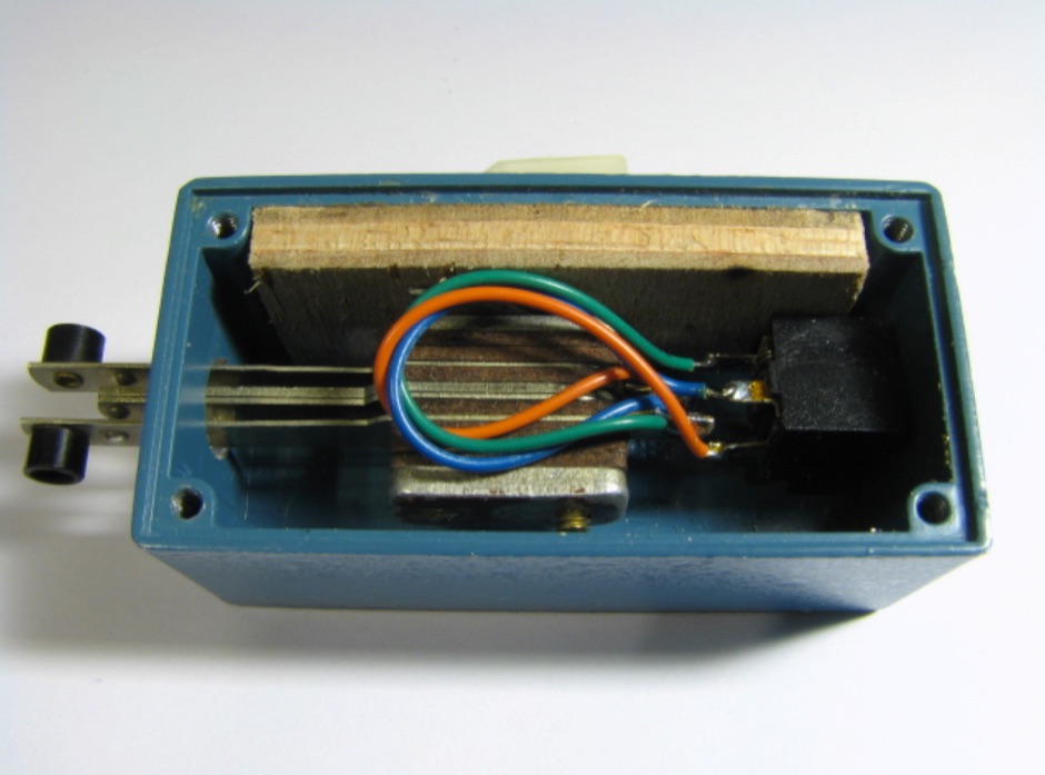 AA5TB home made CW paddles, pictures and construction details
 -
 The document details the optimization and construction of the _Maria Maluca_ antenna, a compact 6-band (20m-6m) directional beam. It presents a comparative analysis of shortwave antenna principles, highlighting the efficiency gains achieved by using an open feeder line and tuner as a resonant unit, contrasting this with the losses associated with traps or capacitive loads in multiband antennas. The resource specifically revisits an older South American 2-element design for 10, 15, and 20 meters, applying modern NEC-based software to develop a six-band version. Performance data is meticulously tabulated, showing impedance, free space gain, gain at 12m height, elevation angle, and front-to-back (F/B) ratio for each band from 20m through 6m. For instance, on 15m, the antenna achieves 5.1 dBd free space gain and 13.72 dB F/B ratio. The construction section provides practical guidance on element assembly using aluminum pipes and hose clamps, detailing the use of a heavy-duty glass fiber reinforced polyamide rod for electrical separation and bending strength. It also specifies the use of 450-ohm _Wireman_ line CQ 552 for the transmission line. The document includes diagrams for rod fixing, an air-wound balun, and a vertical elevation diagram for the 15m band, illustrating its DX qualification. It also discusses the antenna's suitability for portable and expedition operations, noting its compact transport dimensions (max 1.50m length, 12 lb weight) and quick assembly time (under 15 minutes). The author, Dipl.Ing. Helmut Oeller, DC6NY, is identified as a source for material kits.
 -
 The article "Exploring the World of 10 Meter Beacons" by Ken Reitz, KS4ZR, provides an in-depth look at 10-meter beacon operations, focusing on their utility for propagation analysis. It details FCC Rules part 97.203 governing beacon stations, including license requirements, power limits (under 100 watts), and the specified band segment of 28.200-28.300 MHz for U.S. operations. The content highlights the diversity in beacon construction, from converted CB radios to home-brew QRP transmitters, and discusses the robust operating conditions these 24/7 stations endure. The resource presents several case studies of active 10-meter beacon operators like Ron Anderson KA0PSE/B, Domenic Bianco KC9GNK/B, and Bill Hays WJ5O/B, detailing their equipment, antenna setups, and typical signal report volumes. It also introduces the NCDXF/IARU International Beacon Project, which features 18 synchronized beacons worldwide transmitting on 28.200 MHz at varying power levels (100W, 10W, 1W, 100mW) to facilitate propagation testing. The article also covers the PropNet Project utilizing PSK31 on 28.131 MHz and the 250 Synchronized Propagation Beacon Project on 28.250 MHz. Practical advice for monitoring includes using the RST reporting method, understanding the impact of the solar cycle on 10-meter propagation, and tips for setting up a personal beacon, such as frequency selection and power output considerations. The IY4M Guglielmo Marconi Memorial Beacon Robot on 28.195 MHz is also mentioned for its automatic QSO mode. The article concludes with a list of other resources for 10-meter beacon information.
 -
 Article on the HF dual band antenna with construction details and how to add 160 meters to the HF2V
 -
 A quarter-wave vertical antenna design for HF operation offers a practical solution for radio amateurs seeking a compact and efficient multi-band radiator. This project details the construction of a 5-band HF vertical, drawing inspiration from established commercial products such as the _DX COMMANDER_ and the MV6. The design emphasizes ease of assembly and disassembly, making it suitable for portable operations or installations with limited space. The article provides insights into various construction methods and offers practical tips for building a robust yet lightweight antenna. It highlights the benefits of a vertical configuration for DX contacts, particularly on the lower HF bands, and discusses real-world performance observations. The antenna is designed to cover multiple HF bands, providing versatility for various operating scenarios. Operators can achieve significant DX results with this type of antenna, often comparable to more complex arrays, especially when deployed with an effective ground system. The project aims to empower hams to build a capable antenna without significant financial outlay.