Search results
Query: modification rig
Links: 42 | Categories: 0
-
 The G5RV antenna, with an overall length of **31.10m (102ft)**, functions as a 3/2-wave on 20 meters when installed horizontally at 12m (39ft), exhibiting a resonant frequency of 14.150MHz and an approximate resistance of 80 ohms. Its 10.36m (34ft) stub line, designed as a 1/2-wave on 14.150MHz with a 0.97 velocity coefficient, acts as an impedance transformer across other bands, aiming for multiband operation without traps. On 20m and higher frequencies, the G5RV demonstrates improved gain compared to a standard dipole, attributed to the _collinear effect_ from multiple 1/2-waves along the wire. The original design sought a multiband solution for limited spaces, often requiring an Antenna Tuning Unit (ATU) for effective operation across bands like 80, 40, 30, and 20m, particularly with modern solid-state PAs. Variants, such as the F8CI modification, incorporate a 1/4 current balun at the stub line's base for symmetrical-to-asymmetrical transition, known as a _remote balun_. Proper flat-top or inverted-V installation is critical for maintaining symmetry and collinear gain, with inverted-V apex angles below 120° progressively diminishing higher-band performance.
 -
 Members discuss the operation of and modifications to this outstanding QRP rig that covers 160m 70cm with all modes. Site contains a large database of FT-817 FAQs and data files. Antennas, tuners, and power sources are also covered as related to this ultra-compact transceiver.
 -
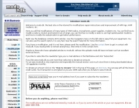 Mods.DK serves as a central repository for **amateur radio modifications**, offering a substantial collection of user-contributed articles. Hams can find detailed instructions for various equipment, from transceivers by Yaesu, Kenwood, and Icom to microphones and power supplies. The database, currently holding 6230 articles, facilitates searching for specific equipment modifications, such as enabling out-of-band receive and transmit capabilities or integrating high-speed packet modems for enhanced data communications. Many entries focus on achieving better performance from existing gear, often detailing how to expand frequency coverage for MARS/CAP operations or optimize radios for 9600 baud packet. The site also includes repair instructions and general improvements for a wide array of HAM rigs and modems, reflecting a community-driven effort to share technical knowledge. Users are cautioned that modifications are not verified by Mods.DK and are undertaken at one's own risk, with potential legal implications depending on local regulations. The platform emphasizes community support, encouraging direct contact with authors or forum discussions for troubleshooting.
 -
 The project details modifications to an ARK-40 QRP CW transceiver kit, specifically replacing its original thumbwheel frequency selectors with a **BASIC STAMP BS-II microcontroller** and an optical shaft encoder. The redesigned control circuitry outputs a BCD code to the ARK-40's synthesizer, enabling more convenient knob-type tuning. This modification significantly alters the user interface, moving from discrete frequency selection to continuous tuning. Operating frequency is presented on an LCD readout, offering two distinct display modes: a "bandspread dial" mode that simulates an analog dial scrolling across the display in 1 kHz increments, and a conventional digital readout with 100 Hz resolution. Pushing the main tuning knob toggles between these modes, providing both rapid band traversal and fine-tuning capabilities. The software for the BASIC Stamp is written in P-Basic, addressing the challenge of accurate analog dial simulation. Physical modifications include fabricating a custom PC Board for the STAMP, mounting it with an L-bracket to the optical encoder, and creating a new front panel. The front-mounted speaker was relocated to accommodate the new tuning knob and display, transforming the **ARK-40 transceiver** into a more user-friendly rig with its built-in CW keyer and 5 watts of power.
 -
 Constructing a **2-meter** J-pole antenna from readily available copper plumbing components offers a robust and cost-effective solution for VHF operation. This design, dubbed the "Plumber's Delight," functions essentially as a half-wave dipole fed by 50-ohm coax via a **gamma match**. It incorporates a quarter-wave copper tubing support, which, when affixed to a metal mast or tower, enhances forward power in the direction of the radiating elements. The original configuration utilized a small ceramic trimmer capacitor for the gamma match, suitable for up to 10 watts. A subsequent modification replaced this with a 50 pF variable capacitor housed in a plastic enclosure, accommodating higher RF power and improving weather resistance. The antenna elements are secured using a copper "T" fitting, and an SO-239 connector mounts directly to this fitting. Performance includes gain away from the support mast, and tuning is straightforward by adjusting the gamma match capacitor for a 1:1 SWR. The total cost for materials, excluding the capacitor and coax, can be under $10.
 -
 Demonstrates building a basic _VOX circuit_ to add voice-operated transmit functionality to HF transceivers that lack this feature. The design utilizes a _1458 dual op-amp_ (two 741 op-amps in one package) to amplify microphone audio and act as a comparator, driving an NPN switching transistor for PTT control. A capacitor, C2, provides the necessary delay before unkeying the PTT, with a variable resistor, R6, allowing adjustment of the VOX level for specific microphones or voices. This low-cost circuit, detailed with a full parts list, offers a practical solution for hams seeking to enhance their budget HF rigs. The author, N1HFX, provides guidance on initial setup, including advice on microphone gain and the use of headphones to prevent speaker audio from re-keying the transceiver. Modifications for adjusting delay time are also included, suggesting increasing R8 to 10K for more delay or decreasing C2 to 22µF for less.
 -
 An assortment of Amateur Radio-related technical articles written for the JUG, the newsletter of the Northern California Contest Club. Topics include unique but simple and useful radio modifications and accessories, and rig reviews.
 -
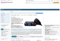
 The RigPix database entry provides a comprehensive technical overview of the Icom IC-746 amateur HF/VHF transceiver, detailing its operational parameters and physical characteristics. It specifies the transmit frequency ranges across 10-160 meters plus WARC bands, 50-54 MHz, and 144-146/148 MHz, alongside receive coverage from 0.03-60 MHz and 108-174 MHz. The resource outlines supported modes including AM, FM, SSB, CW, and RTTY, noting a tuning step resolution down to 1 Hz and a frequency stability of ±5 ppm. Key electrical specifications are presented, such as a 13.8 VDC power supply requirement, current drain figures for RX (1.8-2 A) and TX (Max 20 A), and RF output power ranging from 5-40 W for AM and 5-100 W for FM, SSB (PEP), and CW. The entry details the triple conversion superheterodyne receiver system, listing IF frequencies at 69.01 MHz, 9.01 MHz, and 455 KHz, along with sensitivity ratings for various modes and bands. Transmitter section specifics include modulation systems and spurious emission levels. Additional features like a built-in auto ATU, electronic keyer, simple spectrum scope, DSP, and CI-V computer control are noted. The page also lists related documents, modifications, and an extensive array of optional accessories, including various filters, microphones, and external tuners, providing a complete profile of the IC-746.
 -
 The FTBVR5K software facilitates comprehensive memory management for the Yaesu VR-5000 scanning receiver, supporting operations such as modifying, moving, adding, deleting, masking, and unmasking individual memories. It allows for importing and exporting memory definitions via CSV files, sorting memories by frequency or name, and identifying duplicate frequencies within the receiver's configuration. The program also supports the creation and modification of bank definitions, management of PMS (Programmable Memory Scan) definitions, and adjustment of PMS scanning ranges. Additionally, users can print detailed reports of memories, banks, PMS definitions, rig settings, and S.CALL details, with visual cues like red highlighting for masked memories and yellow for the priority channel. FTBVR5K provides functionality to alter values within the VR-5000's Set and Config menus, and to change S.CALL station names and frequencies. The application operates on standard Windows PCs, including Windows XP, Vista, 7, 8, and 10, requiring an available COM port for transceiver connection, which can be a conventional serial port or a USB adapter. A minimum screen resolution of 800 x 600 is supported, with 1024 x 768 recommended for optimal usability.
 -
 This resource details the construction of a versatile CW/QRSS beacon, designed around a Microchip _PIC16F84_ microcontroller. The project provides a flexible platform for transmitting either standard CW or very slow QRSS signals, making it suitable for LF, VHF, UHF, and SHF applications. It supports two distinct messages, each configurable for speed (from 0 to **127** WPM for CW, or up to **127** seconds per dot for QRSS) and repetition within a six-phase sequence. The core functionality relies on the PIC's EEPROM, which stores all operational parameters, including message content, transmission speeds, phase configurations, and relay control settings. This design allows for parameter modification directly via programming software like _ICProg_ without altering the main program code. The project includes a detailed schematic, a component list, and an explanation of the EEPROM memory mapping for messages, speeds, phase settings, and inter-phase delays. General-purpose outputs (OUT1, OUT2, OUT3) provide dry relay contacts for external control, enabling functions such as power switching, antenna selection, or frequency changes. A 'TRIGGER' input facilitates controlled starts or continuous free-run operation. Sample EEPROM configurations illustrate how to program specific beacon sequences, including message content and relay states.
 -
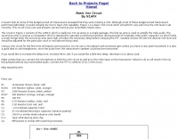
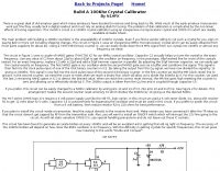 Restoring vintage amateur radio gear often presents challenges with accurate dial calibration due to the non-linear characteristics of analog tuning capacitors. This resource details the construction of a 100 kHz crystal calibrator, a crucial tool for precisely setting the frequency of older rigs lacking digital readouts. The design cleverly circumvents the scarcity and cost of 100 kHz crystals by utilizing a readily available 8 MHz microprocessor crystal, such as a _HC49U_ type, in conjunction with common _CMOS ICs_ like the 74HCT00 quad NAND gate and 74HCT393 dual 4-bit binary ripple counter. The circuit employs a two-stage frequency division process: the 8 MHz crystal oscillator output is first divided by 16 to yield 500 kHz, then further divided by 5 to achieve the desired 100 kHz output. A 5.1-volt Zener diode, _1N4733A_, regulates the power supply for the HCT series logic. The article also provides a modification to produce a 50 kHz calibrator by altering the counter reset logic. Installation involves feeding the output to the receiver front end, ensuring it's post-TR relay to prevent RF damage, and incorporating an ON/OFF switch for the 12V supply line.
 -
 Constructing a portable, high-gain antenna for _AO-40_ satellite operations presents unique challenges, particularly regarding mechanical stability and parabolic accuracy. This resource details the build of a 1.2-meter "brolly dish" antenna, utilizing a non-conducting fiberglass umbrella frame as its foundation. The project outlines a method for achieving a parabolic shape using stressed aluminum fly screen mesh, guided by practical geometry and a temporary dowel template. Key steps include selecting an appropriate umbrella with a suitable f/D ratio (ideally >0.25), removing the original fabric, and precisely cutting and attaching eight segments of fly screen to the struts to form the reflective surface. The construction process, which took approximately five hours for the author, _G6LVB_, resulted in a dish with an f/D of 0.27 (depth=270mm, diameter=1160mm, f=310mm). The article also describes a modification to a _TransSystem AIDC_ feed, incorporating a PCB reflector behind the dipole for easier mounting. Performance tests at a squint angle of 15 deg and a range of 50,000km yielded a signal-to-noise ratio of 33dB on the S2 beacon and 23dB for SSB signals, indicating strong reception. The author notes that the modified umbrella may not close fully without risking surface disfigurement.
 -
 A 500-watt mobile antenna project details the conversion of an old 10m hamstick into a highly efficient, multiband "bugstick" for HF operation. The core modification involves replacing the original coil with 25 turns of 6 turns-per-inch, 1.5-inch diameter coil stock, fabricated from #14 wire. This design, intended for a 3-magnet mount on a vehicle cab, achieves resonance on multiple bands by shorting out specific turns on the coil, similar to a **bugcatcher** antenna. Measurements taken with an MFJ-259 analyzer on a GMC pickup show 0 turns shorted for 20 meters (14.2 MHz), 10 turns for 17 meters, 16 turns for 15 meters, 19 turns for 12 meters, and 23 turns for 10 meters. The construction emphasizes using UV-resistant tie-wraps and #14 solid wire with crimp lugs for robust RF connections, bypassing the fiberglass rod for current flow. A bonus section details a 40-meter version, utilizing 48 turns of 8 TPI, 2-inch diameter coil stock.
 -
 The Collins TRC-75 autotune linear amplifier, owned by JF2SVU, is presented with a focus on its internal modifications. This QRO amplifier utilizes three 4CX250 tubes in parallel for its final stage, delivering 1 KW output power. Notably, the amplifier achieves full power with only 100 mW of RF input, a characteristic often associated with Collins designs. The original 400 Hz power supply has been converted for easier shack integration, and the entire RF and power supply sections have been rehoused into a compact, clean enclosure. The control unit, positioned above the amplifier, features three meters for individual vacuum tube IP monitoring and a multi-meter on the right. A dedicated 7 MHz receiver, recently completed, is also part of this integrated system. The autotune functionality means the main amplifier unit only requires connections for power, control, and coaxial cables, simplifying its operation. Key components like the 4CX250 tubes and NF capacitors are visible, along with the gearing mechanism for the final tank circuit. A timer and relay system manages high-voltage delay and cooling fan off-delay, although the cooling fan's airflow is noted as somewhat insufficient. A central volume control, which experienced a contact issue, is also highlighted.
 -
 Extension to an existing fan dipole originally modeled for 40 20 and 6 meters. This modification will add 80 15 and 10 meter bands.
 -
 Over two decades ago, the Kenwood TS-850S HF transceiver established itself as a robust performer, known for its excellent receiver and versatile operating features. This vintage rig, often found on the used market, continues to be a favorite among many amateur radio operators for its solid construction and reliable performance across the HF bands. Adrian's Yahoo! Group provided a dedicated forum for TS-850S owners to exchange insights, troubleshoot issues, and share modifications or operational tips. Such community-driven platforms were crucial for extending the operational life and maximizing the utility of classic transceivers, fostering a spirit of mutual aid among hams. Discussions frequently covered topics like DSP unit upgrades, common repair challenges, and optimizing the rig for contesting or DXing, reflecting the enduring interest in this particular Kenwood model.
 -
 Sherwood Engineering Inc. (SEI) offers a repository of technical presentations and white papers focused on optimizing amateur radio transceiver and receiver performance. Content includes detailed analyses of _roofing filters_, transmitted IMD, and receiver characteristics, with specific discussions on products like the Drake R-4C and Icom IC-781. Presentations from events such as Dayton Contest University (2008-2014) cover topics like "How To Optimize Rig Performance," "Transceiver Performance: 10 Years of Change," and "Choosing a Transceiver: Far from Simple." Additional white papers address HF mobile antenna efficiency, ground screen alternatives to buried radial systems, and common receiver problems with solutions. The site also provides historical product information for items like the SE-3 MK IV synchronous AM detector and various 455 kHz mechanical and crystal filters, though many products are no longer in production. Receiver test data and alignment tips for the R-4C are also available, offering insights into rig modifications and performance enhancements.
 -
 The Elecraft K2 transceiver requires specific modifications for optimal soundcard digital mode operation, particularly for PSK31. The original article, circa 2001, details initial challenges with manual PTT and speech compression settings. A key modification involves adding headphone audio and a compression disable signal to the K2's microphone jack, utilizing pins 4 and 5. The **COMP0** signal, active low, is shorted to ground via a non-inverting open collector switch circuit, comprising two resistors and two transistors, mounted on the SSB board near U3. This circuit provides effective control of an analog signal line with good noise immunity. The switchbox itself repurposes a computer COM port switch, using only two of its original connectors and four of the nine poles. It integrates a microphone preamplifier, a PTT circuit built with 'flying leads' construction, and RCA jacks for soundcard connections. A trimpot adjusts the audio drive to the K2. The central DB9 connector links to the K2's mic connector via a shielded RS232 serial cable, ensuring proper grounding and signal routing. An external footswitch PTT jack is also included. Further enhancements include a **noise-canceling microphone** preamp based on a QST December 2000 article, adapted for Heil mic elements. This preamp, built with pseudo-Manhattan style construction, provides a gain of approximately 2 by changing emitter resistors (R9 and R16) from 680 ohms to 330 ohms. A 10-ohm series resistor and 47 µF capacitor on the +5V supply mitigate noise spikes.
 -
 Demonstrates the adaptation and construction of a 7-element DK7ZB Yagi antenna for the 4-meter band (70 MHz), utilizing components from a defunct 2-meter CUE DEE Yagi. The resource details the modifications made to the original DK7ZB design to fit the shorter CUE DEE boom length, specifically adjusting element lengths for 6mm rod elements while reusing existing mounting holes for the reflector and last director. It provides precise element lengths for the reflector, dipole (12mm aluminum tube), and five directors, along with a note on cutting elements for transport. The article includes a 4NEC2 simulation file for performance analysis and an SWR plot, confirming the antenna's electrical characteristics. It also specifies the calculation for the quarter-wavelength matching cable using SAT752F coaxial cable, resulting in a 909mm length. Practical application is shown with the finished antenna in operation at JO20XC, listing several activated Maidenhead squares such as JO56PA and JP40KS, validating its effectiveness for portable 70 MHz operations.
 -
 Constructing a high-power 70cm solid-state amplifier presents unique challenges, particularly when aiming for 500 watts output using modern LDMOS devices. This resource details the author's experience building a 70cm amplifier based on a _Freescale MRFE6VP5600H_ transistor, initially from an RFHAM kit. It meticulously outlines the necessary modifications to achieve advertised performance, including optimizing input and output matching, correcting bias circuitry, and ensuring proper output balun connections for stability. The author shares specific adjustments, such as trimming the prototyping board for better transistor fit, drilling additional mounting holes for improved heat sinking, and replacing original matching capacitors with a single _20pf MIN02 metal mica_ for superior output. A critical fix involved jumpering gate decoupling pads to balance the push-pull transistor halves, which increased output to 580W and improved IMD. The resource also highlights a crucial correction to the output balun connection, initially reversed in the _Dubus_ article schematic, which resolved intermittent stability issues. Test results are provided, showing input power, output power, and drain current at 50V, demonstrating the amplifier's performance after modifications. This practical account offers valuable insights for hams undertaking similar high-power UHF amplifier projects, especially those working with LDMOS devices and kit-based constructions.
 -
 Operating the _Icom IC-746_ HF/VHF transceiver often presents specific technical questions, and this resource compiles a comprehensive Frequently Asked Questions (FAQ) document in an ASCII text format. It details common inquiries and solutions related to the rig's functionality, accessories, and potential modifications. The content is structured into distinct sections addressing general information, power supplies, antennas, microphones, keyers, amplifiers, TNC integration, and optional IF filters. The FAQ provides practical guidance on topics such as configuring the internal automatic antenna tuning unit (ATU), selecting appropriate power supplies, and understanding microphone pin-outs. It also delves into advanced subjects like computer control via CI-V, wiring for PSK31 operation, and troubleshooting common issues like low S-meter readings on 2m FM or loose tuning shafts. Specific questions cover the installation of optional IF filters, comparing Inrad versus Icom filters, and optimizing filter combinations for various modes. Furthermore, the document outlines various hardware and firmware modifications, including those for increasing monitor volume, replacing LCD driver transistors, and implementing a "poor man's TCXO." It even touches upon untested modifications, such as replacing PIN diodes in the demodulator. The FAQ also lists manual errata and discrepancies, offering a robust knowledge base for IC-746 owners seeking to optimize their station or resolve operational challenges.
 -
 Modification leaves nearly all of the existing Omni agc circuitry intact, simply add an audio detector which modifies the delay characteristics of the original system by G3IXQ
 -
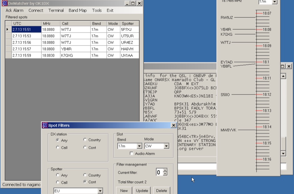 Demonstrates a specialized DX cluster monitoring application, _DxWatcher_, designed for Windows environments. It processes DX spots received via Telnet/Internet, presenting them in a filtered table and a dynamic bandmap. The software integrates with transceivers, specifically the FT-2000, to read VFO frequency and enable one-click tuning to spotted stations. _DxWatcher_ version 1.0.3.0, released on 13 June 2020, includes minor bugfixes and improvements such as enhanced recovery from suspend mode. Key features include configurable bandmap position and size, automatic opening, and bolding of spots received within the last **10 minutes**. The application utilizes the standard _ctry.dat_ file for DXCC country analysis, allowing users to update it for current DXCC status. Source code, developed in C# with MS Visual Studio 2008, is freely available, encouraging modification and sharing while requesting retention of the original author's callsign.
 -
 Documents the construction of a **VHF/UHF** antenna addition for the Buddipole HF antenna system, leveraging the existing Versa-Tee component. The project details the fabrication of a custom antenna mount from angle aluminum, including specific drilling and tapping for 3/16"-24 bolts, and the creation of radials from Simpson Strong Tie Insulation Supports. It specifies radial lengths for 70 centimeters (6 inches from the center stud) and 2 meters (19 1/4 inches), noting the use of wire nuts for safety. The resource outlines the construction of a mast from 1/2" ID PVC conduit, connected with 3/8"-24 connecting nuts and bolts, mirroring the Buddipole's modular design. It describes the integration of a mobile dual-band antenna with a 3/8"-24 mounting stud and the custom coax setup with BNC and **PL-259** connectors. Field testing with an FT-817ND and a separate dual-band SWR meter confirmed good SWR on both 2 meters and the 440-450 MHz section of 70 centimeters, with positive reception reports during Field Day activities. Further, the article describes the creation of a custom carrying solution, including a 22-inch tripod bag and a fabric roll-up, to emulate the portability of the original Buddipole system.
 -
 Loki5ace version 5.3.39.1 is a freeware amateur radio logging program designed for Windows operating systems (XP, Vista, 7) and compatible with Linux Wine. The software offers multiple installation methods, including a portable version (loc5portable.zip or Loce5pack.zip) that does not require administrator rights or Windows Registry modifications, making it suitable for USB stick deployment or limited user accounts. An official installation (loc5acest.zip) is also available, typically installing to C:\Program Files\Hamlok\LokiAce\ and requiring administrator privileges for initial setup and updates, with user-specific settings and database files stored in application data folders. The program's database, Loc4ac.mdb, can be renamed to the user's callsign for personalization. Loki5ace supports context-sensitive help, which requires WinHlp32.exe installation on Windows Vista and 7. The software includes features such as special print functions, Telnet Watch with comment display, and an 'Own QTH' field for location management. Updates can be performed via an in-program function or by manually copying the Loki5ace.zip file, which contains the main executable, Loki5ace.exe, to the program folder. The latest version 5.3.39.0 includes repairs for special prints and enhancements to the Telnet Watch feature.
 -
 The MFJ-971 portable antenna tuner, as stock, lacks a bypass switch and sufficient inductance for efficient 1.8 MHz operation. This modification addresses these limitations by integrating a DPDT switch for direct signal bypass, enhancing operational flexibility. Furthermore, the guide details the addition of a T130-2 iron powder toroid, wound with **29 turns** of enamelled copper wire, to augment the tuner's internal inductance. This increases the maximum inductance from approximately 17µH to around **27µH**, enabling effective impedance matching on the _160-meter band_. The modification involves cutting the wire after the 'L' tap on the original inductor and inserting the additional toroid, ensuring the entire original coil plus the new inductance is engaged when 'L' is selected. This preserves the functionality of other inductance settings while extending low-band performance. The article also highlights a potential RF burn hazard from the variable capacitor nuts on the MFJ-971, even at QRP power levels.
 -
 Maintaining vintage Eddystone receivers often presents unique challenges, as detailed by Victor Jenkins in his refurbishment of an EA12, where his deep understanding of RF circuits ensures optimal performance for daily shortwave listening. Similarly, Gerry O’Hara VE7GUH, a prolific contributor to the EUG website and a trustee, meticulously documented his restoration of an Eddystone S830/2, even addressing an unusual instability issue with a follow-up postscript article and YouTube videos demonstrating the fix. His work, along with numerous other articles on the "Restorations" page, showcases a master's approach to bringing vintage sets back to factory specifications or better. Beyond technical restorations, the EUG also shares compelling historical narratives. One such story recounts the discovery of a long-lost 78rpm recording featuring Eddystone Radio Ltd.'s founder, George Stratton Laughton, and other key figures discussing the company's wartime and post-war contributions to shortwave communications. This six-minute BBC production, transcribed into an MP3 file by Peter Carney, offers a rare auditory glimpse into the company's legacy, highlighting its role in supplying equipment to police, ministries, and expatriate British workers. The community aspect thrives through shared experiences, like Roger Trickett's anecdote about his Eddystone EC10, which has been continuously powered for 50 of its 54 years, traveling across continents and enduring various modifications. Another intriguing account from Roy GM4VKI details the "S640 Identity Crisis," where a seemingly standard S640 receiver turned out to be a masterfully engineered 80/20-meter SSB transceiver built into the original chassis by GI3ZX, showcasing incredible ingenuity from a bygone era of amateur radio.
 -
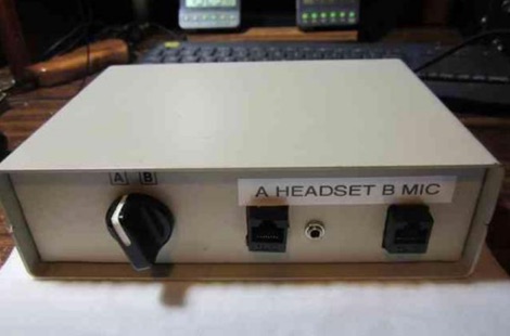 A 15-pin data switch, typically a rotary-knob type designed for DB-25 connectors, forms the basis for this microphone selector project. The resource details the conversion process, which involves replacing the original DB-25 connectors with **RJ-45** or **RJ-12** jacks to accommodate modern amateur radio microphones. It specifically addresses wiring for radios like the Icom IC-706 series (including the IC-7000 and IC-703) and Yaesu transceivers such as the FT-857, FT-897, FT-817, FT-7800, FT-7900, FT-8800, FT-8900, FTM-100, and FTM-400. The design ensures all microphone lines are switched straight through, with separate contacts for external speaker/headphone jacks, allowing simultaneous switching. The project emphasizes the practical application of switching between a headset for net control and a hand mic for rag-chewing without repeatedly plugging and unplugging cables. It highlights modifications to the original concept, such as eliminating a separate PTT jack by integrating PTT into headset cables and building the external speaker cable directly into the selector. The article provides guidance on managing the non-color-coded wiring often found in these data switches by soldering wires one by one from old to new connectors, ensuring correct pin alignment. This approach simplifies the conversion, making it accessible for hams seeking a functional and cost-effective mic switching solution.
 -
 Amateur Packet Reporting System (APRS) operations often require compact, reliable solutions for transmitting position data, particularly for mobile or portable stations. This resource details the construction of the _Tiny Track-I_, a transmit-only APRS tracker designed for straightforward integration with a VHF radio and a Global Positioning System (GPS) receiver. It enables hams to broadcast their location without the complexity of a full-duplex TNC. The project outlines the printed circuit board (PCB) layout and schematic, based on an original design by N6BG, with a personal PCB drawing by SV1BSX. It includes specific component placement and notes an additional 10uF/10V capacitor (C5) for improved IC voltage decoupling, a modification not present in the original N6BG diagram. The unit connects to a computer or GPS via a DB9 female connector. This tracker is ideal for basic position reporting, offering a simple and effective way to participate in APRS networks. Its small footprint makes it suitable for vehicle installations or field deployments where space is limited, providing a **reliable 9600 baud** data stream for location updates.
 -
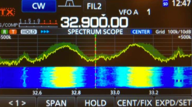 The Icom IC-7300 is a popular SDR transceiver known for its excellent performance in ham bands. However, users have reported issues with reception reliability outside these bands due to ADC aliasing. This phenomenon occurs when the sampling rate of the radio interacts with frequencies outside the intended range, leading to unwanted signals being received. For instance, when tuned between 30 to 36 MHz, users may inadvertently pick up WFM broadcast signals or PMR communications due to aliasing effects. This guide outlines modifications to improve the IC-7300's performance by addressing the low-pass filter design, which is crucial for reducing interference from these unwanted signals. The proposed modifications involve adjusting the low-pass filter on the PA unit to better attenuate frequencies that cause aliasing. Measurements indicate that the original filter design allows significant signal leakage, leading to false receptions. By implementing the suggested changes, users can achieve a notable reduction in unwanted signals, enhancing the overall functionality of the IC-7300. While the modification requires careful soldering, the benefits in performance make it a worthwhile endeavor for serious operators looking to optimize their SDR experience.
 -
 The 222 MHz Transverter project, based on Zack Lau's (W1VT) original July 1993 QEX magazine design, provides an IF of 28 MHz for both transmit and receive paths. Rick Bandla (VE3CVG) contributed supplemental notes and construction details, including modifications to achieve 10 mW output power from an initial 4 mW PEP. The design incorporates three distinct boards: a Local Oscillator (LO), a Transmitter (Tx), and a Receiver (Rx), with an estimated parts cost of just over $150 CDN, significantly less than commercial kits. Construction involves both through-hole and surface-mount components, with specific guidance on mounting MAV and MAR devices, grounding techniques, and component selection. The project details include parts lists, schematics for the LO, Tx, and Rx, and board layouts. Troubleshooting advice emphasizes sequential testing, starting with the LO, then Tx, and finally Rx, using a 194 MHz and 222.100 MHz capable FM handheld for signal tracing. Further enhancements are discussed, such as an optional Tx driver stage to boost output to 100 mW and the potential modification of a Motorola Maxor 80 PA for 222 MHz SSB/CW operation. The resource also covers practical aspects like power attenuation pads for IF radios (e.g., FT817) and considerations for enclosure design, including repurposing a Maxor 80 case. Performance reports indicate successful 70 km contacts with only 4 mW output.
 -
 Initially planned as an article on the R-407 station mast, this project evolved into creating a custom mast kit. Utilizing original materials, the design was modified for cost-effectiveness and practicality in home assembly. The new mast extends to 10 meters, featuring secure connections, a leather-lined base to prevent metal-on-metal friction, and sturdy military-grade anchors. Modifications include lengthened connecting tubes, improved anti-rotation features, and a convenient base design for solo assembly. Ideal for amateur radio operators, this mast provides stability, ease of construction, and versatility, proving more economical than professional products without compromising on performance or reliability. Article in Czeck.
 -
 The document provides a detailed modification guide for the Zetagi HP201 SWR Wattmeter, converting it for HF amateur band usage. It replaces the original circuit with a Tandem Coupler based on the Sontheimer and Frederick directional coupler patent, enhancing accuracy and sensitivity. Key components include Murata toroid cores, scaling resistors, and a new calibration process. Challenges and solutions during the modification process are discussed, ensuring linear results across 160-10m bands. This guide also includes calibration instructions and theoretical insights into the coupler's operation.
 -
 The FT101ZD DDS VFO project replaces the original VFO in the Yaesu FT101Z/ZD rigs with an AD9850 DDS module, providing enhanced frequency control. It uses the original optical encoder and clarifier for compatibility, with a custom 6V power supply modification. The project includes selectable step sizes, a frequency save function, and works with both RX and TX modes. The design involves mechanical and electronic modifications, including SMD components and a custom PIC processor. Calibration ensures accurate frequency output, with further improvements under consideration.
 -
 This report details a modification of a Diamond V2000 antenna, replacing its original two 0.50 m radials with two 1.55 m radials. Initial M5-threaded rods failed to fit; the housing required M6 threads. Custom radials were made using 8 mm OD aluminium tubing and M6-threaded stainless steel ends, secured with nuts machined to 9 mm. SWR issues on 6 m (>2:1) were largely due to a poor counterpoise connection, resolved during reassembly. NanoVNA measurements showed no adverse effects on 2 m or 70 cm. The final setup retains the two 1.55 m radials and original counterpoise. Other operators reported SWR degradation with similar mods—sometimes fixed by adding capacitance—but this was not observed here.
 -
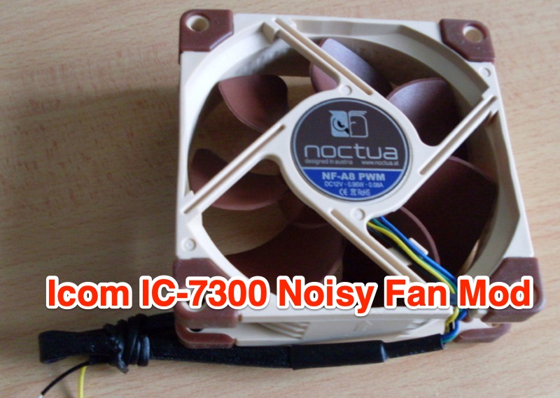 The Icom IC-7300 transceiver's stock cooling fan, a 12VDC unit typically run at 6VDC with a 10VDC transmit kick, is often perceived as noisy. This modification replaces the original fan with a **Noctua NF-A8 PWM** fan, which is described as "silent" even during the initial 10V transmit kick. The resource provides specific wiring details, noting black for negative and yellow for positive connections, and suggests using readily available 2-pin fan plugs for a clean installation. This fan replacement significantly reduces operational noise, improving the user experience of the IC-7300. The Noctua NF-A8 PWM fan is available for under £20 in the UK, making it an accessible upgrade. The modification is presented as a straightforward process, enhancing the rig's acoustic profile without compromising cooling efficiency, based on the experience of Bjorn Eklund, **SM7IUN**.
 -
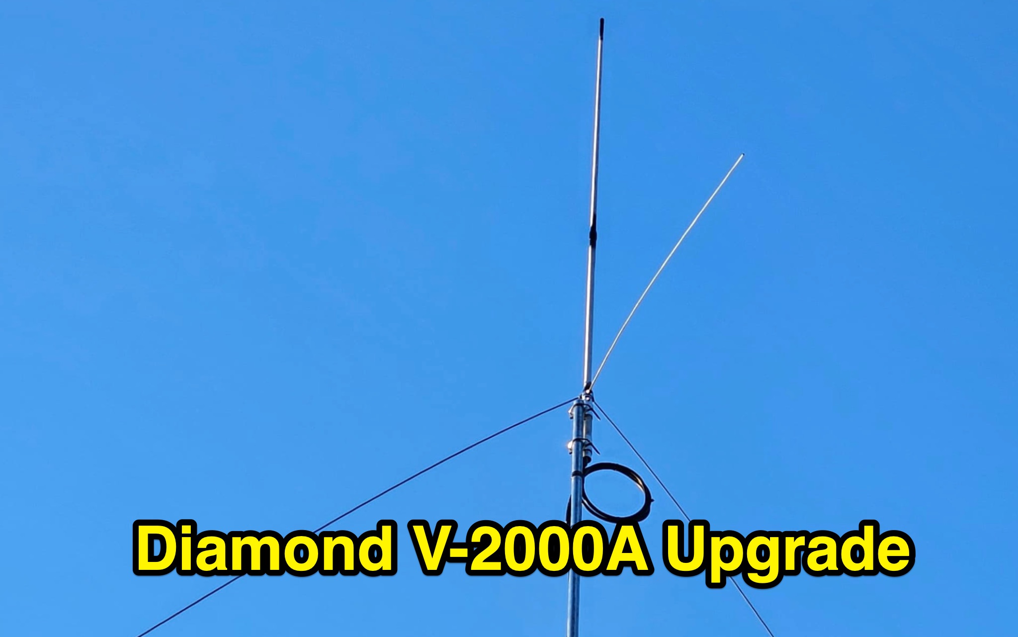 Learn how to enhance the performance of your Diamond V2000A antenna by optimizing the length of the radials. Discover a cost-effective method to create improved radials using simple materials like aluminum tubes and bolts. Explore the benefits of this modification for 6m band, unlocking triband capabilities and better SWR. Find out how a ham radio operator from Europe successfully upgraded their V2000 antenna and achieved impressive results. Save money by DIY-ing your radial enhancements instead of purchasing expensive replacements.
 -
 Operating amateur radio satellites presents unique challenges, particularly concerning antenna design and signal propagation. Juan Antonio Fernández Montaña, EA4CYQ, recounts his three-year journey into satellite communication, starting with initial guidance from EB4DKA. His early experiments involved a portable 1/4 wave VHF antenna with four 1/4 wave ground planes, designed for hand-held use to adjust polarity. This setup, paired with an FT-3000M transceiver, allowed full-duplex operation on **VHF** transmit and **UHF** receive, proving effective for early contacts on satellites like AO27, UO14, and SO35. EA4CYQ's experience highlights the critical role of coaxial cable loss and antenna polarization. After encountering significant signal degradation with longer RG213 runs, he experimented with a 1/2 inch commercial cable, noting improved reception but persistent fading due to varying satellite polarities. This led to the construction of an **Eggbeater II** antenna, an omnidirectional UHF design offering horizontal polarization at the horizon and circular right polarization at higher elevation angles. Subsequent modifications resulted in the directional **TPM2** antenna, which provided sufficient gain for LEO satellites with a wide 30-degree lobe, enabling consistent contacts from his home station. The article concludes with practical insights on the performance of the Eggbeater II for both UHF and VHF, and the TPM2 for UHF, emphasizing their utility for portable and fixed operations. EA4CYQ's journey underscores the iterative process of antenna development and the importance of adapting designs to overcome real-world propagation challenges in satellite communications.
 -
 VE1ZAC's analysis details the performance of **MFJ927** and **SGC239** autotuners with portable HF vertical antennas, specifically comparing 31 ft and 43 ft configurations. The resource originated from challenges encountered during a Maritime QSO Party roving operation, necessitating a lightweight and easily deployable antenna system. Target bands for the contest included 80, 40, 20, 15, and 10 meters, with a maximum power handling of 100 W CW. The author utilized a 30-foot carbon fiber push-up pole to support a vertical wire element, noting its 2 lb weight and reliability. EZNEC modeling was employed to predict performance, showing favorable results for a 30-foot vertical with elevated radials, particularly on 40 and 20 meters. Feedpoint impedance measurements, taken with an AIM4170C, are presented for various HF bands, both with and without a 41-foot RG6 stub designed to reduce reactance on 80 and 20 meters. The stub significantly improved matching on these bands, easing the tuner's workload. Operational tests revealed issues with the MFJ927's reliability during contest setup, leading to reliance on the K3's internal tuner. The SGC239, tested post-contest, performed flawlessly. A detailed side-by-side comparison covers mechanical aspects, connection options, power bias, impedance range, board quality, and documentation. Modifications to the MFJ927, including a new aluminum case, white paint for heat reduction, and upgraded impedance-measuring resistors, are also described.
 -
 An Arduino-based interface provides a remote tuner call command for Icom **IC7700** and **IC7800** transceivers, addressing the lack of a built-in function for external tuners such as the MFJ 998RT. This setup initiates a low-power transmit signal, typically 15 watts, allowing the remote autotuner to perform its matching sequence. The article details the required CI-V line communication and modifications to existing Arduino code, specifically referencing contributions from Jean-Jacques ON7EQ for improved Icom interrogation routines. The system involves a sequence of steps: storing the transceiver's current mode and power, disabling the internal autotuner, activating a control relay to interrupt the amplifier line, switching to RTTY mode at low power, and initiating transmit. The transmit duration is manually controlled by the operator, observing the SWR meter until a low SWR is achieved, then a second button press stops the transmission. A built-in 4-second transmit limit provides a safety measure. After tuning, the routine restores the original mode and power settings, re-enables the internal autotuner, and performs a brief 2-second RTTY transmission for internal tuner adjustment. The circuit diagram includes a Panasonic form 2 relay for amp control and emphasizes critical delays in the Arduino code for stable operation at 9600 baud CI-V communication. Compatibility with logging software like DXLab, N1MM, and N3FJP is noted, with specific interrogation time settings required to avoid conflicts.
 -
 This resource details **cooling modifications** for Ameritron AL82, AL1200, and AL1500 HF amplifiers, specifically addressing heat issues encountered during high-duty-cycle digital mode operation. The author, WD4NGB, observed excessive heat in the tank area and band switch on an AL82, attributing it to insufficient exhaust over the 3-500 tubes and a complete lack of exhaust over the tank area. The modifications aim to prevent common failures such as damaged band switches and deformed insulating materials by increasing airflow and exhaust area. The page describes adding five holes to the chassis for enhanced cooling to the band switch and tank area, alongside enlarging the exhaust area over the inner 3-500 tube and the tank area on the amplifier cover, utilizing expanded metal for safety and RF shielding. The original cover featured 26.25 square inches of exhaust; the modified version significantly increases this to 48.5 square inches over the tubes and introduces an additional 15 square inches over the band switch. These changes are intended to resolve heating problems encountered during heavy, 100% duty cycle use in modes like RTTY or long SSB contests, which typically generate substantial heat. The article also discusses upgrading to a higher output fan, such as the G2E085-AA05-21, and modifying tube sockets for improved airflow and reduced back pressure, citing Tom Rauch (W8JI) of CTR Engineering as a source for parts.
 -
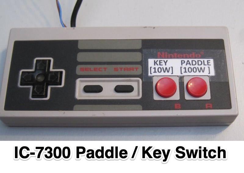 Demonstrates an **Arduino-based** solution for the Icom IC-7300 transceiver, specifically addressing the operational inconvenience of switching between a CW paddle and a straight key. The project leverages the IC-7300's **CI-V bus** (Computer Interface 5) to provide instant keyer type selection and two preset power levels, bypassing the rig's menu system which otherwise requires eight button presses. This implementation utilizes the 3.5mm CI-V connector, leaving the USB port free for CAT control and the internal soundcard, a critical design choice for integrated station setups. The system's utility is particularly evident for CW operators who frequently alternate between keying methods during contesting or general operating. The article details the hardware setup, including an Arduino Nano, a 3.5mm jack for CI-V, and pushbuttons for control. An update in 2023 expanded the project to incorporate an 8-button Nintendo controller, enhancing user interface flexibility and demonstrating the adaptability of the initial design for further customization and feature integration.