Search results
Query: space
Links: 308 | Categories: 4
-
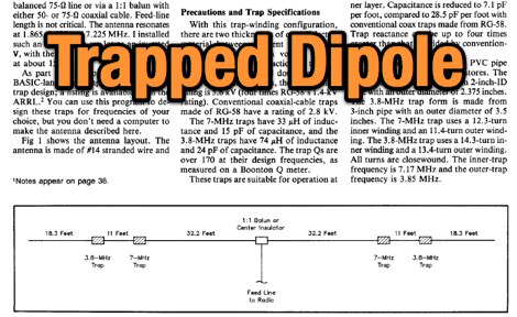 Build a space efficient trapped dipole antenna for 40-80-160 meter bands using RG-58 and PVC pipe. The document provides a brief guide on building a compact dipole antenna appropriate for the 40, 80, and 160-meter amateur radio bands. It explains the materials, building processes, and tuning methods required to provide best performance while preserving space. The paper also discusses theoretical elements of dipole antennas, such as impedance matching and feedline selection.
 -
 140 feet of insulated wire, the first half of which (70 feet) is space wound on an insulated tube.
 -
 The G5RV antenna, with an overall length of **31.10m (102ft)**, functions as a 3/2-wave on 20 meters when installed horizontally at 12m (39ft), exhibiting a resonant frequency of 14.150MHz and an approximate resistance of 80 ohms. Its 10.36m (34ft) stub line, designed as a 1/2-wave on 14.150MHz with a 0.97 velocity coefficient, acts as an impedance transformer across other bands, aiming for multiband operation without traps. On 20m and higher frequencies, the G5RV demonstrates improved gain compared to a standard dipole, attributed to the _collinear effect_ from multiple 1/2-waves along the wire. The original design sought a multiband solution for limited spaces, often requiring an Antenna Tuning Unit (ATU) for effective operation across bands like 80, 40, 30, and 20m, particularly with modern solid-state PAs. Variants, such as the F8CI modification, incorporate a 1/4 current balun at the stub line's base for symmetrical-to-asymmetrical transition, known as a _remote balun_. Proper flat-top or inverted-V installation is critical for maintaining symmetry and collinear gain, with inverted-V apex angles below 120° progressively diminishing higher-band performance.
 -
 The page provides detailed information on the G5RV antenna, its feeder arrangement, and efficient operation on HF bands from 3.5 to 28 MHz. It includes dimensions for installation in limited spaces, variations for different bands, and impedance matching details.
 -
 The Super Loop Antenna page, designed by Jim W4FTU, provides detailed information on the RadioWorks \'Superloop III\' antenna as an alternative for operators with limited space. The page discusses the physical variations of the antenna, including dimensions and materials used, as well as its electrical characteristics such as the 30\' ladder line. The content is useful for amateur radio operators looking for antenna options for the 80 and 40 meter bands, especially those with small lots or zoning restrictions. The page is well-organized and informative, making it a valuable resource for antenna enthusiasts.
 -
 Cubic quad antennas are renowned for their high gain, excellent front-to-back ratios, and low angles of radiation, making them a popular choice among amateur radio operators. This resource provides detailed designs for constructing cubic quads optimized for 2, 6, 10, 12, and 15 meter bands. The lightweight structure can be easily built using fiberglass tubes and central hubs, allowing for portability and ease of assembly. The article discusses the specific dimensions and configurations required for both HF and VHF applications, emphasizing the importance of proper spreader lengths and boom dimensions. It also highlights the challenges of assembling larger cubic quads in limited spaces, offering practical solutions for hams with smaller backyards. With a focus on multi-band operation, this guide serves as a valuable resource for both novice and experienced operators looking to enhance their antenna systems.
 -
 The 160/80m coaxial receiving loop antennas are designed to enhance reception on the top bands while minimizing noise. These antennas are particularly beneficial for operators with limited space, as they can be constructed using lightweight materials, making them portable and easy to deploy. The standalone 80m loop has a diameter of approximately four feet, allowing for easy rotation and installation above existing VHF antennas. Over the years, many amateur radio operators have turned to loop antennas as a viable alternative to traditional beverage antennas. The design allows for significant noise reduction, especially when paired with a quality pre-amplifier. Experimentation with various configurations has led to the discovery that diamond-shaped loops provide optimal performance. Users have reported a noticeable improvement in signal quality, making these loops a valuable addition to any low-band DXing setup.
 -
 May be of interest to anyone wishing to get on 80M (3.5MHz) that have limited space available.
 -
 This resource details the fundamental aspects of deploying longwire antennas, emphasizing ease of construction and installation for shortwave listening (SWL) and broadcast reception. It covers wire gauge selection, suggesting 14 to 24 AWG for general use, with heavier gauges (14-20 AWG) for permanent outdoor installations. Guidance is provided for various deployment scenarios, including indoor setups where the wire can be run around a room, temporary outdoor installations from balconies using light 18-24 AWG wire, and permanent outdoor configurations requiring higher placement and slack for tree movement. Feeding methods are discussed, recommending coaxial cable (50-75 ohms) to mitigate man-made interference, with instructions for connecting only the center conductor to the longwire. Safety precautions are highlighted, particularly avoiding contact with power lines and conductive materials, and managing static electricity buildup by unplugging the antenna after use and bleeding off charges before connection. The article also advises against using outdoor longwires during thunderstorms or snowstorms due to static and lightning risks. Optimal height considerations are presented, advocating for the highest safe placement, ideally a couple of feet above underlying structures, to maintain free air space. The text mentions a personal setup with one end at a roof peak (20 feet) and the other at a 17-foot mast, illustrating practical deployment without strict height requirements beyond safety and clearance.
 -
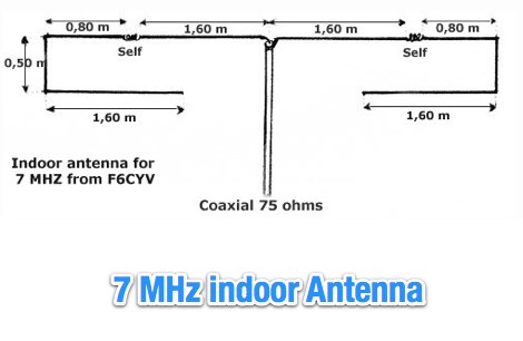 The page provides a project for an indoor wire antenna for the 7 MHz band, based on a design by F6CYV. It aims to help amateur radio operators lacking space to set up an antenna for 40 meters. The author shares their experience using the antenna inside an apartment, noting good reception of European signals and contacts with over 150 countries. The project details the materials and dimensions needed for the antenna, along with tips for optimal performance.
 -
 The **Extended Double Zepp** (EDZ) antenna, a simple wire design, is presented as a means to achieve 3-4 dB of gain on 10 meters, with an overall length of just 43 feet. This resource, authored by WB3HUZ, details several gain antennas suitable for the 29 MHz AM segment, all modeled using EZNEC software at 30 feet above ground. Other designs include a compact rectangular loop, offering more gain than the EDZ and a lower take-off angle, and the **Lazy H**, a bidirectional antenna providing 6 dB gain, which is also workable on 20, 17, 15, and 12 meters. The Bisquare, a diamond-shaped open-top loop, is also featured, providing approximately 4 dB gain and requiring only a single support. These designs are primarily fed with ladder line or open-wire line to simplify matching, though a coax feed option for the EDZ is shown for 10-meter-only operation. The Lazy H, for instance, requires about 16 feet of open-wire line for its half-wavelength elements spaced a half-wavelength apart. An enhanced EDZ Lazy H variant is also discussed, achieving an additional 1-2 dB gain by extending element length to 1.28 wavelengths and increasing spacing to 0.64-0.75 wavelengths. The Bisquare, while primarily a 10-meter antenna, can be adapted for 20 meters by closing the top connection.
 -
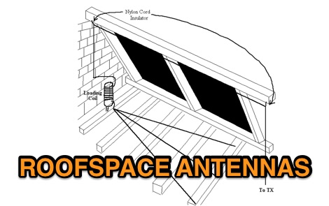 How to build a roofspace antennas and get them to work. Explains how to build an effective antenna in your roof. Very interesting if you don't have possibilities to setup an antenna in your roof.
 -
 Operating a handheld transceiver (HT) while bicycle mobile presents a significant challenge due to the lack of an effective ground plane on a bicycle frame. This project addresses that issue by providing construction details for a 2-meter antenna, specifically adapting the _ARRL Hints and Kinks_ design by Charlie Lofgren, W6JJZ, known as the "Bike 'n Hike Special." The antenna is designed to function efficiently on the 144 MHz band, offering a practical solution for portable VHF communication. The design emphasizes simplicity and portability, crucial for mobile operations where space and weight are at a premium. It details the necessary components and assembly steps, allowing amateurs to build a functional antenna that overcomes the inherent limitations of a bicycle as a radio platform. The original concept was published in the ARRL's well-regarded collection of practical amateur radio solutions. This antenna project enables bicycle mobile operators to achieve improved signal performance compared to a stock HT rubber duck, facilitating more reliable contacts while on the move. It represents a straightforward approach to enhancing VHF communications for active hams who combine cycling with their radio hobby.
 -
 This antenna makes 80 and 160 enjoyable. Less than $50 to hear Europeans all summer on the LF bands seems like a good deal if you have the space!
 -
 Antenna Restrictions, Power Restrictions, RFI Problems, or Limited Space keeping you off the air?
 -
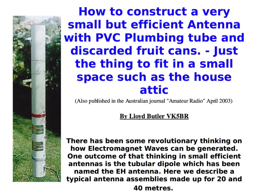 How to construct a very small but efficient Antenna with PVC Plumbing tube and discarded fruit cans. - Just the thing to fit in a small space such as the house attic
 -

-
 Hear VLF audio from NASA online VLF radio receiver in Huntsville, Alabama.
 -
 The RXO Unitenna, a vertical wideband antenna, offers operation across the 7-21 MHz spectrum, covering the 40, 30, 20, 17, and 15-meter amateur bands. This design focuses on achieving a low SWR across a broad frequency range, making it suitable for general HF operation without requiring an external antenna tuner for minor SWR variations. The antenna utilizes a unique loading coil and matching network to maintain efficient radiation characteristics across its operational bandwidth. Construction details within the PDF document include specific dimensions for the radiating element and the counterpoise system, which is critical for vertical antenna performance. The design incorporates readily available materials, simplifying the build process for radio amateurs. Performance graphs illustrate the SWR characteristics across the 7 MHz to 21 MHz range, demonstrating the antenna's wideband capabilities. The document also provides guidance on feedline connection and grounding considerations for optimal field deployment. This vertical antenna configuration is particularly useful for hams with limited space, offering a compact footprint compared to horizontal wire antennas.
 -
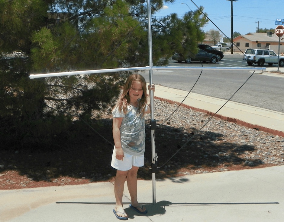
 Presents a practical design for a **crossed-dipole turnstile antenna** specifically engineered for 2-meter Amateur Radio Direction Finding (ARDF) events. The author, WB6RDV, details a robust, omnidirectional, horizontally-polarized antenna, addressing the international ARDF rules requiring such characteristics at a height of two to three meters above ground. This contrasts with the vertical polarization often used in Southern California, highlighting the design's adherence to specific event requirements. The electrical design employs a classic crossed-dipole with a 75-ohm phasing section, resulting in a slight impedance mismatch and an SWR of approximately 1.3:1 with a 50-ohm feedline. Construction utilizes readily available and inexpensive PVC plumbing components and 1/8-inch bronze welding rod for elements. The guide provides step-by-step instructions for mechanical assembly, including drilling element holes at precise 90-degree spacing and preparing the RG-179 matching section. WB6RDV shares insights from his own build experience, discussing the use of plated brass versus aluminum spacers for element attachment and the effectiveness of crimping as an alternative to soldering. The document also covers final assembly, including the integration of ferrite beads as a choke balun and options for weatherproofing and alternative mounting configurations, emphasizing the adaptability of the design for other VHF bands through scaling.
 -
 Galaxy DX 47HP and DX 99V2 models are highlighted, showcasing the manufacturer's current offerings in both amateur and Citizens Band radio transceivers. The site details several amateur models, including the DX 29HP, DX 44HP, DX 55HP, DX 98VHP, DX 33HP2, and DX 94HP, catering to different operational needs and power levels. For CB operators, a range of models like the DX 2547, DX 979, and DX 929 are presented, with specific features such as _StarLite_ front panel lighting for low-light conditions, as seen on the DX 929 and DX 979. The DX 979 is noted for its compact form factor and SSB capability, making it suitable for installations where space is a constraint. Conversely, larger models like the DX 939, DX 949, and DX 959 are available for those with more room, offering features such as blue lighting and integrated frequency counters. The DX 939, for instance, combines aesthetic appeal with functional design, providing clear readouts and robust audio performance. A downloadable CB radio shopping guide is also offered, enabling users to compare Galaxy's product specifications against other radios on the market, facilitating informed purchasing decisions.
 -
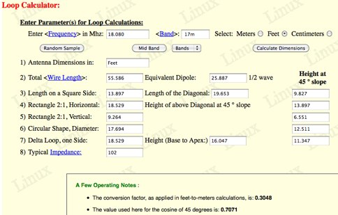 KA1FSB loop calculator give you a quick overview of the feasibility of "squeezing" a loop into your available yard or apartment space. The easy calculator yields a reasonable approximation of dimensions, to within 5% over the amateur bands, using typical wire gauges ranging from 12-18 AWG.
 -
 For amateur radio operators utilizing _APRS_ or requiring an external antenna for their GPS receiver, this resource details the construction of a compact, circularly polarized mobile antenna. The design is based on a classic turnstile configuration, employing two dipoles rotated 90° from each other and spaced a quarter-wavelength above a ground plane. A parallel-plate transmission line, fabricated from printed circuit board material, serves as both the connection method and mounting post for the dipoles, simplifying the feed network for circular polarization at 1.57542 GHz. The article outlines the fabrication process, starting with a 4-inch diameter hobby tin or brass base plate and #14 solid copper wire elements. It specifies using _RG-58/U_ or similar 50-ohm coax, with an 8-foot maximum length to minimize loss at the GPS frequency. The parallel-plate transmission line is constructed from two 2-inch lengths of single-sided _FR-4_ or G10 PCB material, 0.062-inch thick, with a specific 45° microwave turn cut on the active side. Final assembly involves an 8-ounce cream cheese container as a radome, and the article discusses the self-phased quadrature feed method to achieve circular polarization without a coaxial phasing line, resulting in an omnidirectional pattern suitable for GPS satellite reception.
 -
 Short dipole antenna for 40 meter ham band. Can be put up in the space required for a 20 meter dipole.
 -
 Demonstrates adapting the _Moxon rectangle_ antenna design for 2-meter VHF operation, highlighting its unique characteristics for specific applications. It details how the antenna's small size and distinctive far-field pattern, typically associated with HF, can be effectively utilized on VHF. The resource provides modeled dimensions for three different element diameters (1/4", 1/2", 1") and discusses the necessary adjustments to maintain optimal performance, such as gap spacing and element lengths, to achieve a 50-Ohm feedpoint impedance. The article presents predicted performance data, including gain (dBi), front-to-back ratio (dB), and feedpoint impedance (R, jX) across 144, 146, and 148 MHz. It analyzes free-space azimuth patterns and discusses the antenna's behavior when horizontally and vertically polarized over ground, including its suitability for fixed installations, repeater applications, and even satellite communications. Construction considerations, such as bending elements and maintaining critical gap distances, are also addressed. Furthermore, the content explores advanced configurations like using two back-to-back rectangles for broader coverage and a crossed-Moxon setup for circular polarization, suggesting potential for urban communication and satellite work. The author, _L. B. Cebik, W4RNL_, emphasizes the Moxon's strengths in broad bandwidth, wide beamwidth, and high front-to-back ratio, rather than maximum gain.
 -
 Building a directional antenna for limited space, M0MRR shares his experience constructing a 10-meter Moxon rectangle. Initially using fiberglass fishing poles and a plastic breadboard, he achieved a 1:1.2 SWR across the band with 50 watts, making contacts as far as PY2TO from the UK. The design incorporates 10-amp power cable for elements and RG58 coax with crocodile clips for feeding, demonstrating a cost-effective approach. His field observations confirm the directional properties, noting European signals fading when facing Stateside, and receiving better reports from stations in the antenna's favored direction. While not formally measured, the front-to-back ratio appears effective. The initial build was somewhat flimsy, intended for temporary deployment, but proved effective for DX. Later, M0MRR constructed a more robust 10-meter Moxon using tubular aluminum pipe, indicating an evolution in his design approach for durability. The project highlights practical antenna building for small backyards, emphasizing the benefits of a directional antenna even with modest power.
 -
 The _Morgain_ antenna for 40/80 meters is a straightforward and cost-effective wire antenna design, requiring careful tuning for optimal performance across two bands with low SWR. Construction involves creating 12 cm PVC spacers with three holes for wire insertion, along with larger terminals for anchoring and connector housing, which should be sealed with silicone. The provided measurements detail the specific lengths for the antenna elements, crucial for achieving resonance on both 40m and 80m bands. Tuning the Morgain antenna necessitates fabricating four wire segments with pins to temporarily connect and adjust the bridging points symmetrically for both 40m and 80m. This iterative process, though time-consuming, ensures the antenna functions effectively for decades once the precise connection points are soldered and protected. The design emphasizes ease of construction and long-term stability, making it a practical solution for hams seeking a dual-band wire antenna.
 -
 This antenna is intended as a simple, inexpensive solution for the newcomer to experiment across the 40m band (7.0-7.2MHz) when only restricted space is available
 -
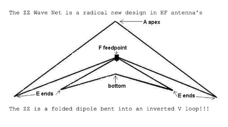 ZZ Wave Net is a 40 & 80 meter full wave loop designed to fit on a city lot. ZZ Antenna is a folded dipole bent into an inverted V loop
 -
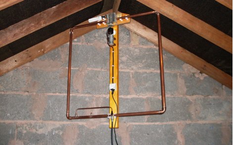 The resource provides detailed information about a five-band indoor magnetic loop antenna designed for amateur radio operators. This antenna is capable of operating on the 20, 17, 15, 12, and 10 meter bands, making it a versatile choice for various HF communications. Constructed from a single 3-meter length of 22 mm copper tube, the design emphasizes compactness and efficiency, which is particularly beneficial for operators with limited space. The page includes insights into the construction process, tuning, and operational tips, catering to both novice and experienced users. In addition to the technical specifications, the resource also discusses the advantages of using a magnetic loop antenna indoors, such as reduced interference and improved performance in urban environments. It serves as a practical guide for those interested in building their own antenna, offering a straightforward approach to antenna design and construction. Overall, this resource is a valuable addition to the toolkit of amateur radio enthusiasts looking to enhance their station with an effective indoor antenna solution.
 -
 Arrl document about invisible antennas and indoor systems. It is important to consider that few compromise antennas are capable of delivering the performance one can expect from the full-size variety. But the patient and skillful operator can often do as well as some fellows who are equipped with high power and full-size antennas. The "cliff-dweller" may not be able to "bore a hole" in the band as often, and as easily, but DX can be worked successfully when band conditions are suitable.
 -
 Constructing a compact, directional antenna for the 6-meter band presents unique challenges, especially for operators with limited space or those seeking portable solutions. This project details the build of a 50 MHz Moxon rectangle, specifically engineered for balcony or temporary mast deployment, using readily available materials from a typical hardware store. The design emphasizes ease of construction and portability, allowing for quick setup and breakdown. The antenna's dimensions are precisely calculated using _Moxgen_ software for 50.200 MHz, ensuring optimal performance. Key construction techniques include using aluminum U-channel for elements, fiberglass driveway markers for insulation, and cable ties for secure assembly. The guide provides detailed instructions for fabricating the driven element, reflector, and boom, including a clever method for creating foldable element tips for transport. Performance observations indicate a respectable front-to-back ratio, capable of reducing an S7 signal to S0 when pointed away, and a modest gain over a simple wire antenna. The design incorporates a ferrite bead choke balun at the feedpoint to mitigate common-mode current and reduce shack noise, a critical consideration for urban or apartment-based operations.
 -
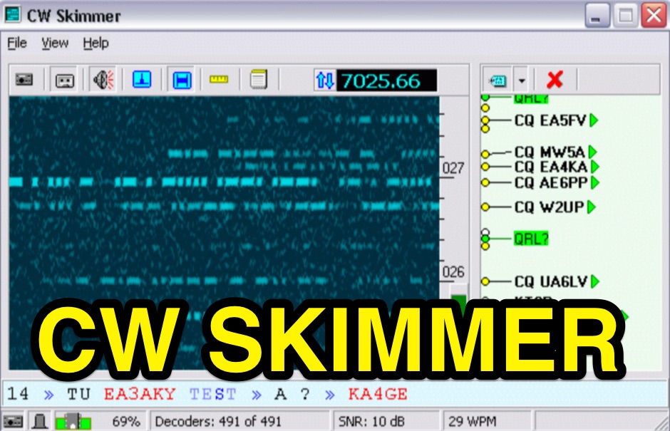 CW Skimmer 2.1 employs a high-sensitivity CW decoding algorithm based on Bayesian statistics, enabling simultaneous decoding of up to 700 CW signals within a receiver's passband on a 3-GHz P4 system when paired with a wideband receiver. The software features a fast waterfall display with sufficient resolution for visual Morse Code interpretation, automatically extracting and labeling callsigns on the waterfall traces. Extracted callsigns are exported as DX cluster spots via an integrated Telnet cluster server. The application includes a DSP processor with a noise blanker, AGC, and a variable-bandwidth CW filter, alongside an I/Q Recorder and player. It supports both 3 kHz radio passbands and wideband SDR receivers like SoftRock, RF Space SDR-IQ/SDR-14, SRL QuickSilver (QS1R), HPSDR Mercury, and Microtelecom Perseus. System requirements specify Windows XP/7/8/10 (32-bit or 64-bit), a Pentium-4 2.5 GHz for wideband operation or 1 GHz for 3-kHz radios, a COM port for CAT control, and a stereo sound card supporting 48 kHz sampling. It integrates with Elecraft KX3, Icom IC-7300/IC-7610, and Flex 6000 series radios, with documentation available for various setup configurations.
 -
 Presents a detailed construction guide for a 2-element _Moxon rectangle_ antenna optimized for the 10-meter band, designed by L. B. Cebik, W4RNL (SK). This resource demonstrates how to build a compact beam antenna using readily available hardware store aluminum tubing, fitting within a 12-13 foot width. It highlights the antenna's performance characteristics, including a gain comparable to a 2-element Yagi (11+ dBi) and a front-to-back ratio exceeding 20 dB between 28.3 and 28.5 MHz, with an SWR below 2:1 across the entire band. The design emphasizes direct 50-ohm coax connection without a separate matching system, though a 1:1 choke _balun_ is recommended. The guide provides practical advice on element construction, corner fabrication using L-stock or radius-bent tubing, and the critical side-to-side length adjustment for SWR optimization. It details the feedpoint assembly using a chassis-mounting coax connector and discusses element-to-boom plate options, including spar varnished plywood or LE plastic. The author's experience with a test model on a 20-foot mast confirms stable feedpoint characteristics and excellent performance even at lower heights. The document also includes insights into the antenna's free-space azimuth patterns, noting a broad forward lobe and significant front-to-back rejection. It contrasts the Moxon with traditional Yagis, positioning it as an effective, home-buildable alternative for compact sites or _Field Day_ operations, particularly beneficial during periods of increased 10-meter activity.
 -
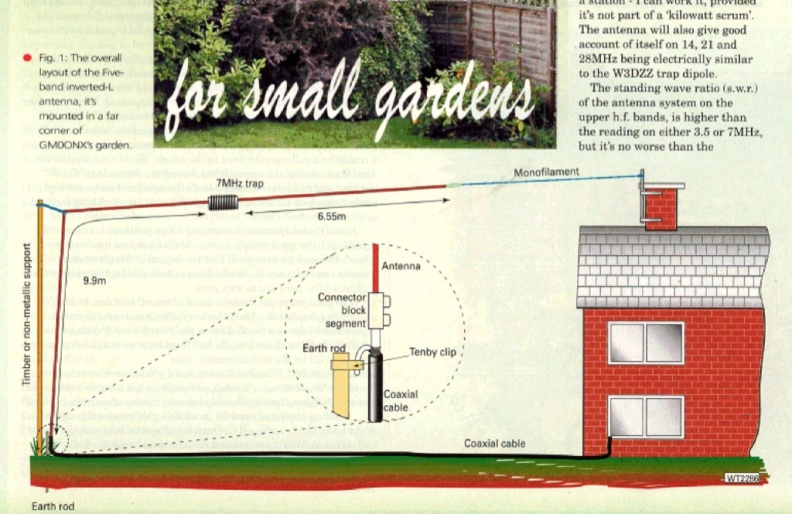 The Inverted L antenna is a versatile and efficient design suitable for small gardens, allowing amateur radio operators to operate on multiple bands. This project outlines the construction of a 5-band inverted L antenna, which can cover HF bands effectively. The design is particularly advantageous for those with limited space, as it requires minimal ground space while providing good performance. The antenna can be easily constructed using common materials, making it accessible for both beginners and experienced hams. In this guide, GM0ONX shares detailed instructions on how to build the inverted L antenna, including dimensions and tuning tips. The project emphasizes the importance of proper installation and grounding to ensure optimal performance. Additionally, it discusses the antenna's compatibility with various transceivers and the potential for portable operation. This resource is ideal for hams looking to enhance their station with a multiband antenna that performs well in limited space.
 -
 Here is a simple and easy to build antenna in a Delta Loop configeration that should make 10 and 12 meters lots more fun if you have a limited space situation o
 -
 Multi-band centre-fed antenna capable of very efficient operation on all HF bands, specifically designed with dimensions which allow it to be installed in gardens and other open spaces which accommodate a reasonably-straight run of 31.1m (102 ft) for the flat-top standard model.
 -
 A 10-meter J-Pole antenna, detailed in QST February 1950, offers a straightforward solution for hams operating with restricted space. This design, originally presented by W1BLR, is a **half-wave radiator** fed by a quarter-wave matching stub, providing a low-angle radiation pattern beneficial for DX. The article describes building the antenna from readily available materials like copper pipe, emphasizing its simplicity and effectiveness for **single-band operation**. The J-Pole's inherent design provides a good impedance match to 50-ohm coaxial cable without the need for an external tuner, a significant advantage for portable or minimalist stations. Its nondirectional pattern ensures coverage in all directions, making it a versatile choice for general operating on the 28 MHz band. The construction plans are clear, allowing even those with basic workshop skills to assemble a functional antenna.
 -
 This listing was put together by ve7vdx on the USENET rec.radio.amateur.space, and is updated weekly there
 -
 A half sloper antenna for 160 meter band Italian translation of a WD8DSB article appeared in a QST issue during 1998. This article presents a **Reduced-Size Half Sloper Antenna for 160 Meters**, designed for amateur radio operators with limited space. By utilizing a 40-foot tower or a tree, you can build an efficient antenna that slopes down, achieving a 2:1 SWR bandwidth of 120 kHz. This innovative design allows for effective communication on the "Top Band," making it ideal for winter DXing.
 -
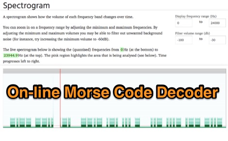 Demonstrates an online **CW** audio decoder tool, currently under active development, designed for analyzing and decoding Morse code. Users can upload audio files containing Morse code or record live audio input via a microphone, with processing handled entirely in JavaScript using the Web Audio API. The software analyzes the audio, attempting to determine the pitch and speed, and then decodes the message, providing options to compare the decoded output against a predefined message or a perfectly timed version. The interface allows for setting optional comparison messages, character speed in WPM, and Farnsworth speed. It also features interactive charts for visualizing the audio analysis, where users can zoom with the mouse wheel and pan by dragging. Specific buttons highlight different element types such as intra-character space, inter-character space, extra elements, missing elements, and replaced elements, aiding in detailed signal analysis. Built-in test files are available for immediate analysis, allowing users to quickly evaluate the decoder's performance. The tool is noted to work with specific browsers and is presented as a testing platform for user feedback, indicating ongoing refinement of its decoding algorithms and user interface.
 -
 The ZS6BKW multiband HF antenna, a design by ZS6BKW (G0GSF), functions effectively on multiple HF bands without requiring an Antenna Tuning Unit (ATU) for 40, 20, 17, 12, 10, and 6 meters. This antenna, approximately **27.51 meters** (90 feet) long with a 12.2-meter (40-foot) open-wire feeder, is a direct descendant of the _G5RV_ but offers superior multi-band resonance. It can be deployed as a horizontal dipole or an inverted-vee, with the latter requiring only a single support and maintaining an apex angle of at least 90 degrees to prevent signal cancellation. Performance data, recorded with an MFJ Antenna Analyser, indicates SWR values of 1:1 on 7.00 MHz (40m) and 14.06 MHz (20m), with SWR below 1.3:1 on 17m, 10m, and 6m. While primarily designed for these bands, the antenna can be adapted for 80m, 30m, and 15m with an ATU, preferably at the balanced feeder's base. The use of 450-ohm twin-lead for the feeder is recommended over 300-ohm for improved strength and reduced losses, especially in adverse weather conditions. This design, originally published in _RadCom_ in 1993 and featured in Pat Hawker’s "Antenna Topics," provides a compact and efficient solution for HF operation, particularly for those with limited space or resources.
 -
 For amateur radio operators seeking a compact, directional antenna for the 10-meter band, this resource details the construction of a Moxon Yagi beam. The design utilizes readily available PVC pipe for the boom and elements, with specific measurements derived from the Moxon Rectangle Generator software. It outlines the assembly process for the main boom and end sections, providing critical dimensions for element spacing and overall length to achieve resonance at 28 MHz. The Moxon configuration offers a smaller footprint compared to a traditional Yagi, making it suitable for limited space installations. The article provides practical guidance for hams interested in a DIY antenna project, emphasizing the use of common hardware store materials. It specifies a 1 1/4" PVC schedule 40 pipe for the main boom and details the use of tees, reducing bushings, and 45-degree elbows for the element ends. Key measurements like the 55" spacing for the ends and the 150 3/4" overall length are provided, enabling replication of the design. The Moxon's inherent wide beamwidth and good front-to-back ratio make it an effective choice for DXing on 10 meters.
 -
 The K5OE 2-meter vertical mobile antenna design, detailed in this resource, employs a 3/8-wavelength vertical section complemented by four shortened radials, forming an off-center-fed vertical dipole. This configuration creates a self-contained lower half, enhancing efficiency compared to traditional 1/4-wave monopoles relying on vehicle bodies for a ground plane. The article specifies construction using PVC components, 10-gauge insulated wire for elements, and provides precise dimensions in both inches and centimeters for the 25-3/16" (64 cm) vertical and 7-3/16" (20 cm) radials. Performance data indicates an honest 3 dBi of gain at 6 feet elevation (2 dBi free-space), with a pattern favoring the horizon, suitable for Low Earth Orbit (LEO) satellite communications. At 20 feet high, the same antenna exhibits almost 6 dBi of gain, with a nominal 50 Ohm feedpoint impedance at 146.850 MHz. Tuning instructions involve trimming element lengths, with the author achieving a 1.2:1 SWR by pruning the mast to 24-3/4" and radials to 7". The resource highlights the antenna's effectiveness for mobile LEO satellite uplinks, particularly at low elevations, and its suitability for fixed, mobile, or portable operations. The flexible wire elements allow for easy folding, making it a practical choice for backpacking. The original design by K5OE was previously hosted on aol.com.
 -
 F6EZX presents a detailed account of constructing a compact, multi-band _Levy antenna_ for portable holiday operations, specifically addressing issues with local QRM from a previous _Deltaloop_ setup. The article outlines the design criteria, including multi-band operation on 40m, 30m, 17m, 15m, 12m, and 10m, a symmetrical configuration to reduce interference, and a low take-off angle for DX. Construction involves 2x 10.3m radiating elements and a 15.3m open-wire feeder (ladder line) with 7cm spacing, made from 1.5mm2 copper wire and foam pipe insulation spacers. Theoretical calculations, referencing F9HJ's "_Les antennes Levy_" book, guide the determination of element lengths and feeder impedance characteristics, aiming for a good match across bands with a commercial antenna tuner. Initial field tests with the _VCI Vectronics VC300DLP_ tuner showed a 1:1 SWR from 80m to 10m, with some difficulty on 17m. The antenna, mounted as a 45-degree slopper with the high point at 12m, successfully facilitated DX contacts to South America, particularly Chile and Argentina, suggesting a lower take-off angle compared to the previous Deltaloop which favored Brazil. The Levy antenna significantly reduced TVI/RFI, attributed to its improved symmetry and greater distance from the QRA. While signal reports on 15m and 20m were 1-2 S-points lower than the Deltaloop, its performance on 40m and 30m was comparable, fulfilling the design goals for a portable, low-cost, multi-band solution.
 -
 Presents G0GSF Brian's ZS6BKW antenna, a refined iteration of the classic G5RV, offering improved performance across multiple HF bands. The design emphasizes specific radiator and ladder line lengths to achieve lower SWR on 40m, 20m, 17m, 12m, and 10m, making it a practical choice for operators seeking a single wire antenna solution. The document includes critical dimensions for the flat-top and the 450-ohm ladder line section, which are key to its multiband resonance characteristics. Unlike the original G5RV, the ZS6BKW aims for direct 50-ohm feedpoint impedance on several bands, reducing the need for an external antenna tuner. My field experience with similar optimized dipoles confirms that precise construction, particularly the ladder line length, is paramount for realizing the intended SWR benefits. This design offers a compelling alternative for hams with limited space or those preferring a less complex antenna system.
 -
 CuteSDR Open-Source application for MacOSX , Linux, and Windows designed to run with RFSPace SDR receiver
 -
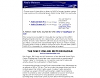 Icom PCR 1000 at NASA Marshall Space Flight Center monitoring meteor signals on 67.3 mhz.live.
 -
 This resource presents a detailed analysis of the W6NL 2-element 40-meter **Moxon Yagi** antenna, covering its design, construction, and measured performance characteristics. It outlines key specifications such as a free-space gain of 6 dBi, 11 dBi at 70 feet, and a direct 50-ohm feed. The document highlights the antenna's physical attributes, including 52-foot elements, a 27-foot boom, and a weight of 75 pounds, engineered to withstand 125 mph winds. Modeling was performed using **AO6** and K6STI software, with a focus on the unique functions of the transverse tip elements for Moxon coupling, physical balance, efficient capacitive loading, and reduced wind load. The presentation includes comparative data, showing the Moxon's superior front-to-back (F/B) ratio and wider bandwidth compared to traditional loaded Yagis. Performance graphs illustrate the SWR, gain, and F/B across the entire 40-meter band (7.0-7.3 MHz), comparing measured results against calculated values. Azimuth and elevation patterns demonstrate high F/B, with the antenna's pattern matching that of a full-size 3-element Yagi on a 30-foot boom. It also notes a gain difference of 1.5 dB down relative to a K3LR 4-element Yagi on a 50-foot boom, providing practical benchmarks for performance evaluation.
 -
 W5ALT Indoor Vertical Antenna is a base loaded vertical antenna that can be tuned on almost all HF bands by adjusting a big coil. Operating a ham radio station from an apartment in Maracaibo, Venezuela, the author demonstrates effective communication with over 100 countries using a custom-built indoor vertical antenna. Addressing common misconceptions, the design uses a balanced approach with radials and a base-loaded vertical element made from affordable materials. The antenna fits discreetly indoors, covers 6 to 40 meter bands, and achieves acceptable SWR with an MFJ tuner. Despite limited space and typical apartment challenges, the setup enables reliable DX contacts, confirmed by numerous QSL cards, proving indoor antennas can perform well in constrained environments.