Search results
Query: J Pole
Links: 829 | Categories: 19
Categories
- Antennas > 20M > 20 meter Dipole Antennas
- Antennas > 40M > 40 meter Dipole Antennas
- Antennas > 6M > 6 meter J-Pole Antenna
- Radio Equipment > HF Portable Antenna > Buddipole
- Antennas > C-Pole
- Antennas > Dipole
- Manufacturers > Antennas > HF > Dipole Antenna
- Antennas > Fan Dipole
- Antennas > Folded Dipole
- Antennas > J-Pole
- Antennas > Resonant Feedline Dipole
- Antennas > 15M
- Antennas > 30M
- Shopping and Services > Antennas
- Manufacturers > Antenna Parts > Fiberglass tubing
- Manufacturers > Antennas > HF
- Antennas > T2FD
- Antennas > W3DZZ
- Antennas > Wire
-
 6 Meter J-Pole from 450 Ohm Ladder Line a quickie project
 -
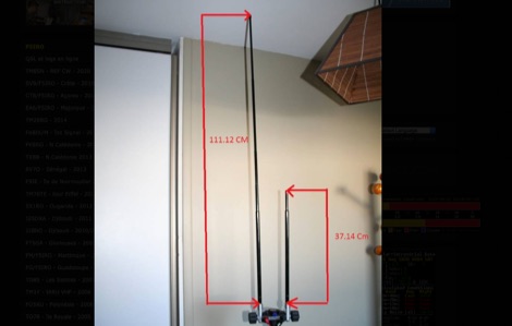
 Experimenting a 20 40 meter short coil loaded dipole antenna with the goal to keep the total length under 40 feet so that the dipole can be mounted on two 20 foot fiberglass pole to make a 20/40 meter rotatable dipole.
 -
 Amateur radio antennas manufacturer based in Italy. Produces HF end-fed, dipoles, and other wire antenna types, mono band and multi band antennas.
 -
 Supporting wire antennas with squid poles
 -
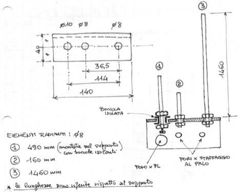 A multiband J-Pole antenna project that cover 144,220 and 430 MHz. The articles includes several pictures of this multi-band antenna, including handmade schematics and diagrams, project is mainly in Italian
 -
-
 Constructing a high-performance RF spectrum analyzer up to 1000 MHz requires careful attention to component selection, shielding, and circuit isolation. This resource details a project that improves upon the _Spectrum Analyzer for the Radio Amateur_ design by Wes Hayward (W7ZOI) and Terry White (K7TAU), incorporating ideas from Scotty Sprowls' project, particularly his 1013.3 MHz IF bandpass cavity filter. The analyzer utilizes a Mini-Circuits SRA-11 mixer with a sweeping local oscillator from 1013 to 2013 MHz, feeding into a 4-pole copper pipe cavity filter. The design employs a second SRA-11 mixer with a fixed 1024 MHz LO to produce a 10.7 MHz final IF. This signal then passes through narrowband resolution filters and is processed by Analog Devices AD603 and AD8307 ICs for IF amplification and logarithmic detection, driving an oscilloscope in X/Y mode. The project emphasizes modular construction, using salvaged components and double-sided FR4 material for PCBs, with critical notes on minimizing spurious images through effective shielding and proper voltage regulation for each module. Key components include a Z-Communications V585ME48 VCO for the first LO and a Z-Comm V583ME01 VCO controlled by a Motorola MC145151 PLL for the second LO. An optional Hittite HMC307 step attenuator and K&L 5L121-1000/T5000-O/O low-pass filter manage RF input. Tuning procedures for the 10.7 MHz IF resolution filter are also detailed, showing before-and-after spectrum views.
 -
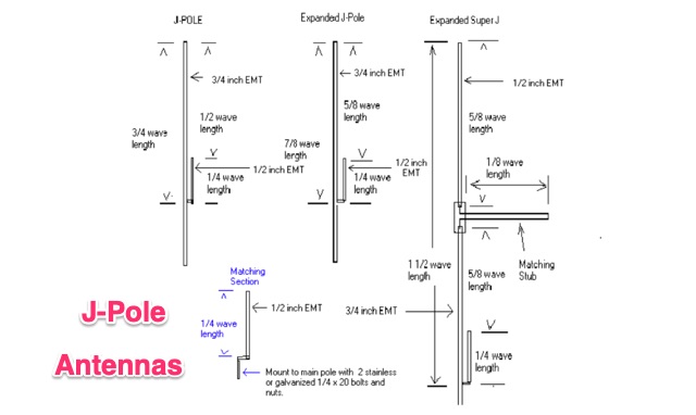 The standard J-Pole antenna is a end fed 1/2 wavelength antenna, in this article is explained also how to build an expanded Super J Pole that provides about 4.5 dbd gain. These antennas can be built from EMT electric conduit pipe
 -
 An experimental prototype of an asymmetrical hatted vertical dipole antenna that can work on HF bands 20 to 10 meters band. The AHVD Vertical dipole is an upside-down T design
 -
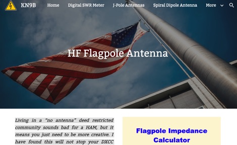 Living in a no antenna deed restricted community sounds bad for a HAM, but it means you just need to be more creative. I have found this will not stop your DXCC activities and many of my local HAM club members will agree
 -
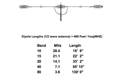
 Constructing a multi-band fan dipole for HF operation presents unique challenges, as VE2XIP demonstrates through his 2012 project to replace an existing commercial antenna. He details the process of calculating wire lengths using the 468/frequency formula, emphasizing the critical importance of equal leg lengths for each dipole element. The author shares practical insights gained from building at ground level, noting how elevation impacts resonant frequency and SWR, particularly for lower and higher bands. VE2XIP's experience highlights the iterative nature of antenna tuning, starting with the lowest frequency band (80m) and working upwards. He provides a specific example of trimming calculations and offers a clever tip for accurate wire removal. The article also touches on the mechanical aspects, such as dowel spacing for wire support and the benefits of a pulley system for repeated raising and lowering during the tuning process. Field results showed significant performance gains over the previous Alpha-Delta DX LB Plus, with **20 dB over 9** signal reports on 80m compared to 57. The project cost around **$100** for hardware, proving a cost-effective alternative. The author also discovered a bonus 6m capability and achieved an inverted-V _obtuse angle_ of approximately 115 degrees, contributing to a surprisingly stealthy installation.
 -
-
 STAR-H Corporation specializes in extremely wideband dipoles and compact low-profile antenna systems for military, emergency management, commercial operations and consumer wireless applications.
 -
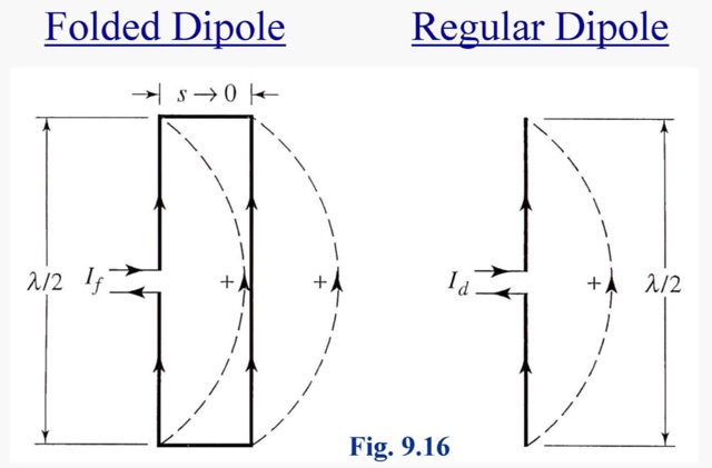 A folded dipole is an antenna, with two conductors connected on both sides, and folded to form a cylindrical closed shape, to which feed is given at the center.
 -
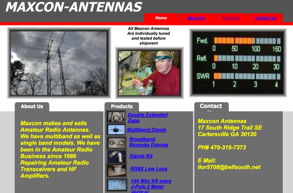 Maxcon makes and sells Amateur Radio Antennas. Double extended Zepp antenna, multiband dipoles, bazooka antennas, and VHF Jpole, made in USA
 -
 The IK7IMP personal page provides details on the _Ham Portal_ software, an Italian-language application designed for managing amateur radio websites, including an online logbook feature. The resource also mentions the development of a J-pole antenna project, indicating a focus on practical radio construction and design. Content on the site covers general amateur radio topics, with specific mentions of equipment from manufacturers like Yaesu, Icom, and Kenwood, alongside antenna brands such as KLM and Tonna. The page serves as a hub for Icilio Carlino's amateur radio activities, offering insights into his interests in DXing, contesting (CW), and general radio operation. It also includes information relevant to the local amateur radio community in Lecce and Salento, Italy, referencing the Associazione Italiana Radioamatori (ARI) and the IQ7AF project.
 -
 This DIY vertical multi-band Windom antenna offers a practical and effective solution for amateur radio enthusiasts seeking a versatile and compact antenna for HF communications. Its simplicity of construction, multi-band capability, and favorable performance make it a valuable addition to any radio shack. The article provides detailed instructions on constructing the antenna and balun, along with diagrams and component specifications. Field tests demonstrated successful contacts with stations across Europe and North America on 14, 18, and 28 MHz. The antenna exhibited comparable performance to a W3DZZ dipole and outperformed a Cobweb antenna on 18 MHz. Low noise levels were observed, effectively suppressing background noise.
 -
 A trap antenna dipole covering two differen bands made reusing an old 160/80m inverted vee antenna.
 -

-
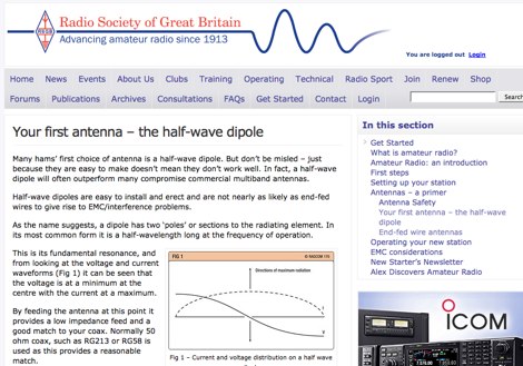 RSGB article for beginners. How to build a dipole antenna, construction tips and correct setup of inverted-ve dipole antennas
 -
 Antenna may be made practically from any wire (strand, solid) having a reasonable diameter 0.5 2.0 mm (24- 12 AWG). Antenna may be installed at any balcony of 3 to 6 meter length.
 -

-
 Sort of similar to the one of the 6m omni. Instead of using twin-lead, this design makes use of a more or less regular double bazooka antenna (coaxial dipole). Your attention shall be drawn to the available standart literature, such as Rothammel. In order to "compute" the dimension, Karl Rothammel mentioned that the total length of the dipole shall be 95% of the free-space wavelength. The short-circuit bridges (closing the folded dipole) are to be placed at a distance-fraction being equal to the velocity factor of the coax cable used, which will be 66% using RG-58 or RG174.
 -
 This antenna is an off-center fed spiral dipole for 40 meters. The spiral dipole is very compact, making it well-suited for limited space (like an apartment patio), while the off-center feed gives the antenna some multiband capability.
 -
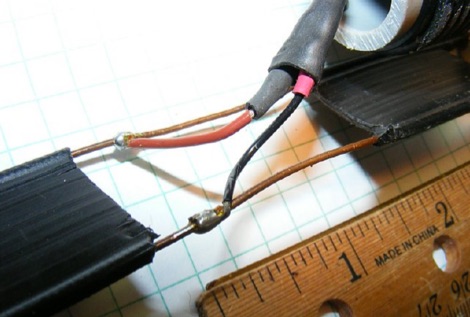
 A little gadget was found in an article in QST, made with 1 pair of powerpole connectors a resistor and two leds
 -
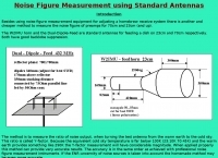 Measuring noise fiugre on the W2IMU horn and the dual-dipole-feed
 -
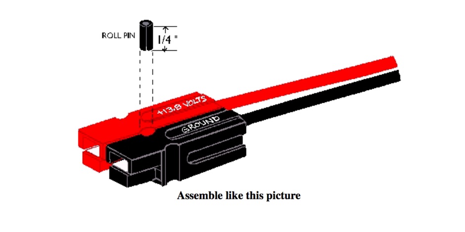 Anderson PowerPole 15/30 Amp Connector
 -
 Why build antennas out of copper and not aluminum or stainless steel. Selecting the best metals for antennas evaluating the conductivity factor.
 -
 How to setup and configure the buddipole antenna in the J-Pole mode for the six meter band
 -
 The OCFD Off-Center-Fed Dipole Antenna is an excellent multiband antenna that is relatively simple to construct, yet gets quite decent performance.
 -
 This is a standard calculation method that can help you while tuning dipole antennas, by adjusting wire lengths. This method can be used also when you need to add lenght to your wires, and can be additionally used to quarter waves vertical antennas
 -
 A fand dipole antenna home made for the 7,14,50 MHz. This article descbribes how to homebrew the antenna, hot to setup and some SWR measurements.
 -
 The video delves into the fascinating science behind antennas, which are crucial for receiving and transmitting electromagnetic waves. It explains how antennas convert electric signals into electromagnetic waves for transmission, and how they operate through the oscillation of positive and negative charges in dipole arrangements. Practical antenna implementations, such as dipole antennas for TV reception and Yagi-Uda antennas with reflectors and directors, are also discussed alongside modern dish TV antennas with parabolic reflectors for signal processing. It's a comprehensive overview of how antennas work and their significance in communication technology.
 -
 A multi-band off centre fed dipole, designed to operate on all bands from 40m (7MHz) to 6m (50MHz). Author claims it will operate on 40, 30, 20, 17, 15, 12 and 10m without an ATU (SWR <3:1) plus 6m with an ATU.
 -
 A simple portable dipole antenna for the 40 meter band using a total lenght of 18 meter. It can be used for 80 to 10 meters coverage using a antenna tuner.
 -
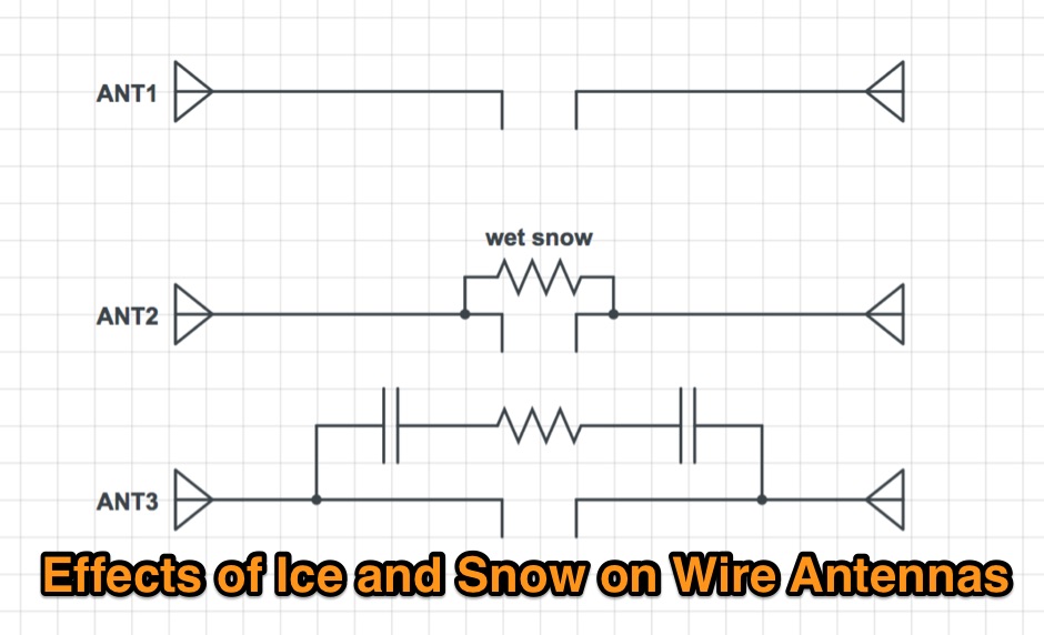 Effects of ice an snow in a wire dipole antennas
 -
 The resource, "Conventional Use of Transmission Line," meticulously details the operational principles of transmission lines, emphasizing the Transverse Electromagnetic (TEM) mode of energy transfer. It clarifies that for a line to function purely as a transmission line, all currents must be confined internally, with external fields ideally zero. The discussion differentiates between balanced and unbalanced lines, asserting that while both require equal and opposite currents within the conductors, the key distinction lies in the voltage relationship of each conductor to the surrounding environment. It highlights that a good antenna pattern does not inherently confirm proper feeder balance, and that common-mode currents can lead to RF in the shack and increased noise levels, even without pattern distortion. The article further explains that a transmission line can become a radiating conductor if energy is applied in a non-TEM mode, leading to common-mode issues. It cites classic texts like Jordan and Balmain's "_Electromagnetic Waves and Radiating Systems_" and Kraus's "_Antennas_" to support its definitions of TEM mode operation. The content also explores non-transmission line applications of parallel or concentric conductors, such as _coaxial dipoles_ and _folded dipoles_, which intentionally operate in non-TEM modes for antenna functionality. The author, _W8JI_, stresses that simply measuring equal currents is insufficient to confirm a balanced feeder; phase and voltage balance to ground are equally critical.
 -
 The ZS1J/B beacon operates on 28.2025 MHz with 5 Watts output to a half-wave, end-fed vertical antenna, initially installed in 1977 as ZS5VHF near Durban. The 10-meter transmitter is a modified 23-channel CB radio, and the identification keyer uses a diode matrix unit with TTL ICs from the same era. After relocation to Plettenberg Bay in 1993, the beacon has been in continuous service, with additional QRP transmitters later installed for other bands. In 1994, a single-transistor, 80-meter, 0.5-watt QRP transmitter with a half-wave dipole was added on 3586 kHz, followed by a 160-meter, 0.5-watt unit on 1817 kHz. A 30-meter, 0.5-watt transmitter was installed in 1996, operating on 10.124 MHz. In 2002, a 40-meter QRRP beacon on 7029 kHz, with an output of 100 microwatts, achieved DX reports up to 1100 km from ZS6UT in Pretoria. Best DX reports for the 80m and 160m beacons came from 9J2BO.
 -
 One of the featured products, the V350 CAMP, is a multiband vertical antenna covering 6 to 80 meters, priced at R$ 799,90, demonstrating the range of ready-to-use solutions available. The inventory includes various antenna types such as **HF**, **VHF**, and **UHF** designs, along with dual-band options like the J-Pole Dual V/UHF for R$ 235,00. For those building their own arrays, the store stocks essential components like element holders, clamps, junction boxes, and aluminum plates, alongside specialized items such as the KIT Isolador Central Dipolo - 01DX for R$ 99,90. The shop also provides a comprehensive selection of installation hardware, including diverse antenna mounts, PTT supports, and various coaxial cables like RG58 and RG213, with prices up to R$ 849,90 for RG213. Connectors such as UHF male PL259 and various adapters are readily available, ensuring compatibility for different setups. Additionally, specialized items like side handles for popular transceivers such as the FT857/891 and IC7300 are offered, catering to specific equipment needs. Beyond antennas, the store supplies practical accessories like transport bags, 12V power cables for transceivers, and even branded merchandise like the Antena Kit mug. Rodrigo Gonçalves, PP5BT, manages the operation from Blumenau, SC, Brazil, providing direct contact via WhatsApp at +55 47 9.9985.0155.
 -
 A portable home made wire dipole antenna that works on 40 30 and 17 meters band.
 -
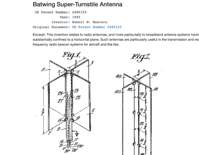 Patents of most popular antenna models including Zeppelin Antenna, Beverage Antenna , Franklin Antenna , Yagi-Uda Antenna , Sterba Antenna , Rhombic Antenna , Turnstile Antenna , Folded Dipole Antenna , Coaxial Antenna , Slot Antenna , Discone Antenna , Quad Antenna Element , Log Periodic Antenna , Swiss Quad Antenna
 -
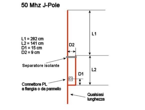
 The page provides information on a simple 50MHz J-Pole Antenna project based on the DK7ZB design. It explains the principle of the Wireman-J-Pole, the feeding process, practical mounting, and simulation results using MMANA GAL. The content aims to guide amateur radio operators in building their own J-Pole antennas for the 6-meter band.
 -
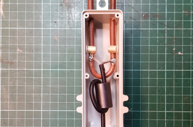 A homemade Jpole antenna for 70 cm band made with 6mm copper pipe
 -
 On 28.219 Mhz it puts out a whopping 3.85 watts into an inverted V dipole at about 30 ft.
 -
 Free ham radio utilities written in LabVIEW includes Open Wire Calculator, Dipole Peak/Null Angle Calculator, a Coil-Shortened Antenna Calculator ad interesting Round Coil Inductance Calculator and a Skyloop Antenna Calculator
 -
 A portable operation experience with a SpiderBeam pole during a contest, testing wire antennas, like dipole and delta loops configurations on 20 40 and 80 meters band.
 -
 The J Pole antenna is a good omnidirectional antenna that can be used for portable or fixed station usage. It does not need a ground, and neither complex feed systems. It can be homemade with simple material and in several ways.Article in Italian
 -
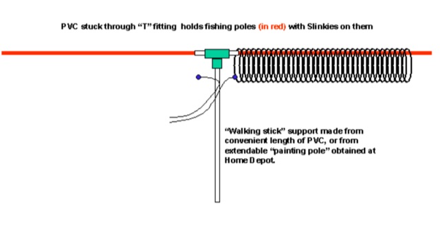 A Multiband Slinky Coil for the PAC-12 portable Antenna, can be used also as a dual PAC-12 dipole by James Bennett
 -
 A rotary dipole antenna for 30 meters band. Each arm is about 12.5 ft and is constructed from telescoping fibreglass flag/fishing poles and short lengths of aluminium tubing. Two short lengths of glass-fibre rod were used to insulate the arms from the supporting hardware.
 -
 The Tri-pole antenna, a clever modification of a standard dipole, allows for dual-band operation by integrating a third element. This design effectively shortens the overall dipole length by 10 to 20 percent, simplifying antenna rotation and offering a compact footprint. KK4OBI's article delves into the operational principles, using a 6 and 10-meter Tri-pole as a primary example, and provides comprehensive instructions for constructing any Tri-pole antenna within the 6 to 15-meter range. Key to the Tri-pole's performance is its off-center feed, necessitating a common mode choke at the feed point for optimal tuning and reduced noise. The author outlines a methodical approach to determining element dimensions, starting with a vertical element frequency calculated as 0.47 times the sum of the desired upper and lower band frequencies. This calculation, along with K-values derived from trend lines, guides the initial lengths for the horizontal arms, demonstrating how a 10m-6m Tri-pole can achieve a total horizontal length 78% shorter than a conventional 10-meter dipole. Tuning and balancing are critical, with the article detailing adjustments to arm lengths and the vertical element to achieve balanced SWR values, as validated through 4NEC2 simulations. Radiation patterns are analyzed at various elevations, showing gains around 5.7 dBi and favorable take-off angles for DX contacts. Construction details specify aluminum tubing dimensions, U-bolts, and an SO-239 connector, emphasizing the importance of a ferrite-based choke for wideband operation.