Search results
Query: drive on
Links: 772 | Categories: 1
-

-
 Developing operational amateur radio equipment for the 134 GHz band presents significant technical challenges, particularly in frequency generation and stability. This resource details the construction of a 134 GHz system, outlining its architecture with separate transmit (Tx) and receive (Rx) modules, each employing a local oscillator (LO) and RF head units. The system utilizes a dual Flann 50 GHz lens-type horn antenna configuration for optimal signal coupling. The transmit path incorporates an LMX2541 synthesizer chip operating at approximately 2.8 GHz, referenced by a 10 MHz double-oven Morion OCXO for exceptional stability. This signal is multiplied through a series of stages (X4, then X2) to generate a 22.4 GHz signal, which subsequently drives a dual series diode multiplier to produce the final X6 signal for 134 GHz operation. The receive side features an anti-parallel diode mixer coupled to a 144 MHz transceiver via a preamplifier, ensuring effective downconversion. Operational mode is CW, achieved by keying a multiplier stage. The project includes images of the Tx and Rx head units and describes a successful 3.5 km test with G8ACE, demonstrating stable signal tones due to PLLs locked to OCXOs at both ends, confirming the system's robust performance.
 -
 This paper discusses the sources of feed line currents and the methods used to control them.
 -
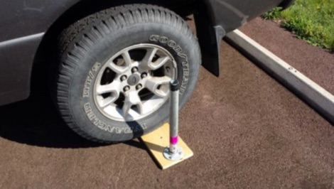
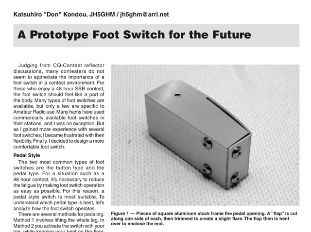 A prototype of a switch foot made on a square aluminium stock frame
 -
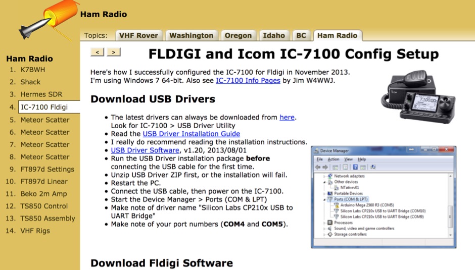 How to configure the ICOM IC 7100 to correctly work with FLDIGI on Windows 7 64 Bit. How install USB drivers and how to properly set COM ports and how to configure CI-V
 -
 A multi-band off centre fed dipole, designed to operate on all bands from 40m (7MHz) to 6m (50MHz). Author claims it will operate on 40, 30, 20, 17, 15, 12 and 10m without an ATU (SWR <3:1) plus 6m with an ATU.
 -
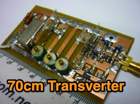
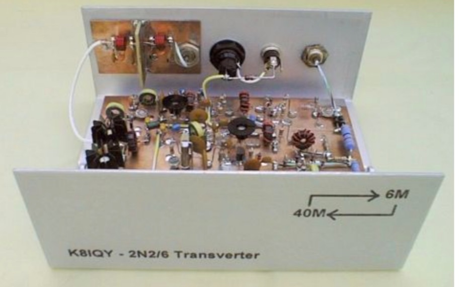 This project is a 40 meter to 6 meter CW "no tune" transverter using ten 2N2222 transistors and one 2N2907. The transverter requires 2 watts of drive from a 40 meter cw transceiver and outputs 2 watts on 6 meters.
 -
 The World Radiosport Team Championship (WRTC) is a unique on-site ham radio competition, typically held every four years, bringing together top operators globally. Unlike traditional contests where participants operate from their home QTH, WRTC competitors travel to a designated location and operate from identical stations under field conditions, ensuring a level playing field. Past events have taken place in diverse locations such as Seattle (1990), Slovenia (2000), Russia (2010), and Italy (2023), showcasing the international scope of this **radiosport** challenge. Because each WRTC event is organized by a dedicated, volunteer-driven committee, historical information and results often become dispersed across various online platforms. This resource serves as a centralized repository, diligently collecting and preserving data from all previous WRTC competitions. It provides a consistent point of reference for participants, enthusiasts, and researchers interested in the history and evolution of this premier **DX contesting** event. The WRTC Sanctioning Committee officially endorses this site, ensuring its accuracy and completeness.
 -
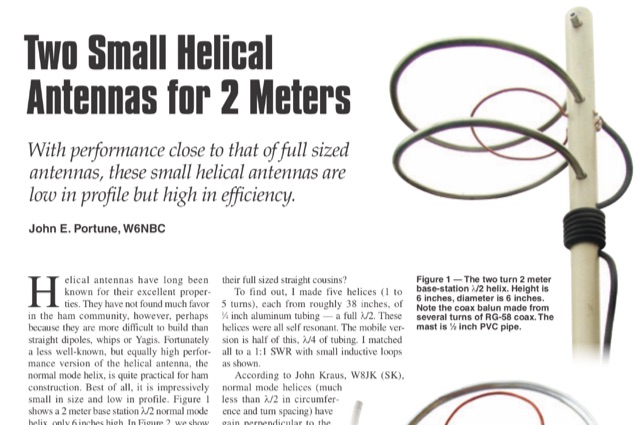 This article is about two excellent small helical antennas for the two meters band. With performance close to that of full sized antennas, these small helical antennas are low in profile but high in efficiency.
 -
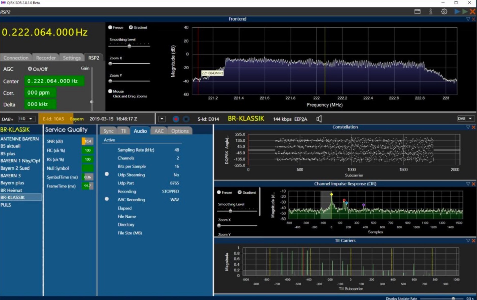 Software Defined Radio, QIRX is 64-Bit software, based on TCP/IP raw data, running with any RTL-SDR dongle being driven by rtl-tcp.exe.
 -
 Quads beams consist of 2 1 wavelength (approximately) loops, ordinarily arranged so that one is the driven element and the other is the reflector. In this project author explains how to build a two element Quad Antenna for the 28 MHz.
 -
 If you thought you knew everything about balun performance characteristics, there is an important figure of merit you may have neglected
 -
 Article on operating aids and band usage during solar minimun periods. Author tries to explain what can we expect on the HF bands during a solar minimum period and which approach to be used to understand band openings.
 -
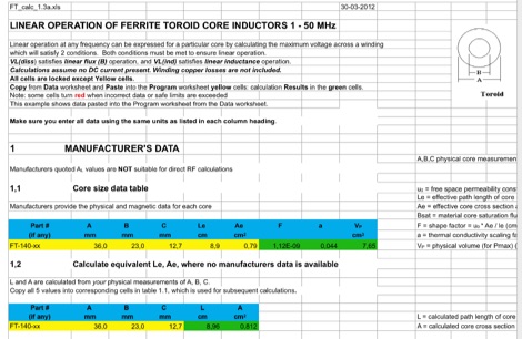 This EXCEL Program Worksheet calculates the safe operating conditons for a toroidal transformer operating between 1 and 50 MHz. Manufacturer data for complex permeability, magnetic dimensions, and saturation flux density must be available. Some core types which are commonly used in amateur transmission are included. The program produces limiting winding voltages for linear operation and temperature rise over the range of frequencies and power specified.
 -
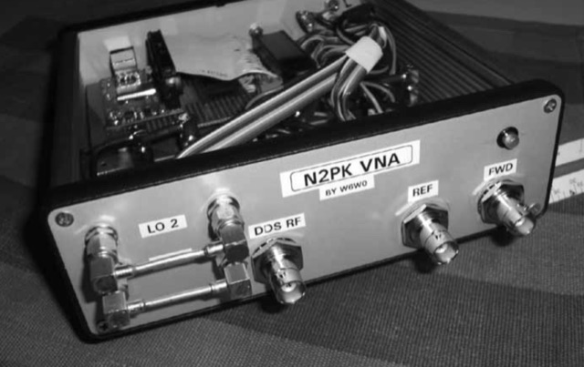
 Internal Bluetooth interface for miniVNA, Bluetooth connection to the PC allow Full cordless operation with ao external components
 -
 Thsi article describes a microcontroller driven semi-automatic antenna tuner capable of handling power levels up to 150 watts. The device is a low pass filter tuner manually tuned by setting the optimized L/C combination by hand and then storing the values into the EEPROM of the mictrocontroller to recall them later (seperately for each band from 80 to 10 meters including WARC bands)
 -
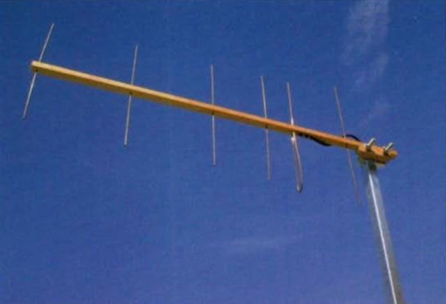
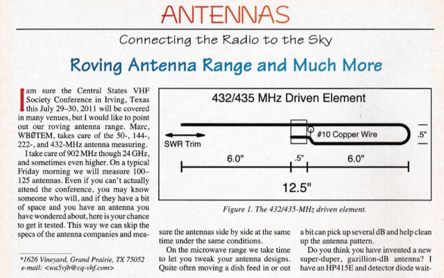 A 18 elements Yagi antenna for 432/435 MHz as published on 2011 CQ VHF magazine
 -
 This is a synopsis of a talk presented to the Sydney VHF DX GROUP by VK2ZAB on how, when and why is convenient to build a Yagi antenna stack.
 -
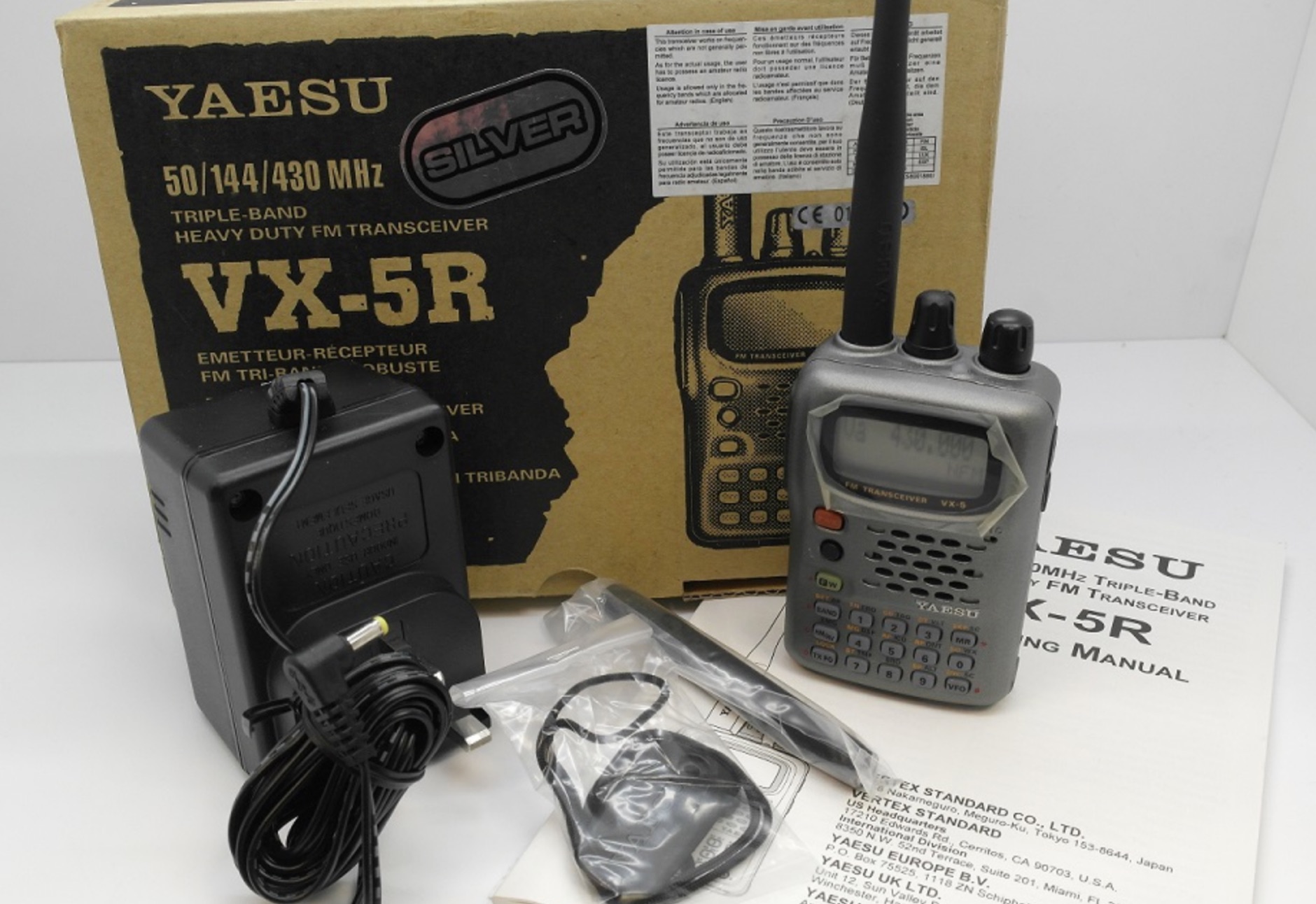 Guide to the Yaseu VX5r, Modes, Memory Banks, Buttons, SET commands, How to save a memory, Tricks and Memory Channel Listing
 -
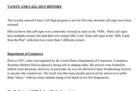 This resource provides a historical analysis of amateur radio call sign assignment policies in the United States, detailing regulatory shifts from the Department of Commerce to the Federal Radio Commission (FRC) and subsequently the Federal Communications Commission (FCC). It documents the evolution of call sign issuance, from early reissuance practices in the 1920s to the implementation of the Group Call Sign Assignment System on March 24, 1978. This system categorized call signs (e.g., 1x2, 2x1, 1x3, 2x3 formats) into groups A, B, C, and D, correlating with license classes such as Extra, Advanced, General, and Novice, and specifying prefixes for contiguous U.S. and territorial areas (e.g., _AH_, _KP_, _KL_). The document further details the legislative process leading to the modern Vanity Call Sign program, initiated by a petition in June 1990 and formalized by the Omnibus Budget Reconciliation Act of August 10, 1993. It outlines the FCC's adoption of final rules on December 23, 1994, and the subsequent fee structure, with the first vanity call sign issued on May 31, 1996, at a cost of **$30.00** for a ten-year term. The ARRL's proposed "starting gates" implementation strategy is also described, which phased in eligibility for vanity call signs based on license class and prior holder status. DXZone Focus: Historical Document | Regulatory Analysis | Call Sign Formats | Fee Structure
 -
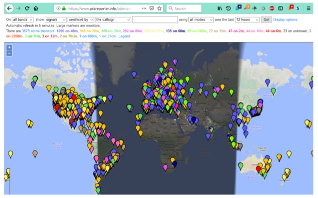 PSK Reporter,is a powerful tool for monitoring your FT8, JT65 or PSK signals around the world. But, even if you are not transmitting on any of these modes it can still be a great propagation tool for determining which bands are open and to where in the world signals from your area are being heard.
 -
 A rotary dipole antenna for 30 meters band. Each arm is about 12.5 ft and is constructed from telescoping fibreglass flag/fishing poles and short lengths of aluminium tubing. Two short lengths of glass-fibre rod were used to insulate the arms from the supporting hardware.
 -
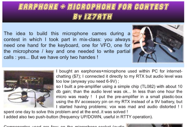 Adapting a common PC earphone with microphone to connect to a transceiver via a homemade pre-amplifier, using a simple chip with aprox 10 db gain. Includes a schematic diagram
 -
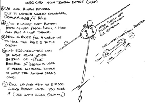 Schematic drawing and instructions for the construction of a simple portable dipole for use in low power and portable operations
 -
 The project in this article illustrates how to do this in a simple and low cost way so that you can easily access the microwave bands using the existing HF or HF/VHF transceiver as IF.
 -
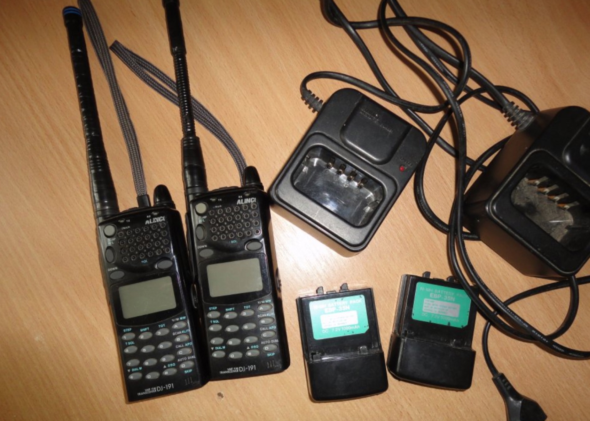 CERT Communications Team Procedures Alinco DJ-191 quick reference in a four pages PDF file
 -
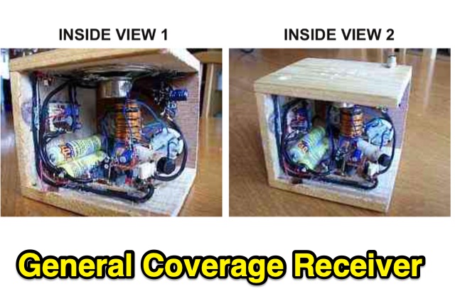 This is a compact three transistor regenerative general coverage receiver with fixed feedback. The sensitivity and selectivity is relative good, especially on the LF and MW bands, as can be expected with this simple design.
 -
 High Speed Multimedia (HSMM) radio, as introduced by John Champa, K8OCL, represents a significant advancement in amateur radio's digital capabilities, moving beyond traditional keyboard modes like packet radio. This initiative, driven by ARRL's Technology Task Force, focuses on developing high-speed digital radio networks capable of up to 20 megabits per second. HSMM primarily facilitates digital voice (DV) and digital video (ADV), enabling real-time video transmission from emergency scenes to an EOC without expensive ATV gear, often requiring only a laptop, a PCMCIA card, a digital camera, and a small antenna. The working group's initial efforts concentrate on cultivating microwave skills within the amateur community to build and support portable and fixed high-speed radio-based local networking, or **RLANs**. These networks prove invaluable for RACES and ARES organizations, as well as homeland security and other emergency communications. Field Day exercises and simulated emergency tests (SETs) are encouraged to hone skills in rapid site surveys and deploying broadband HSMM microwave radio networks, with examples like linking Field Day logging stations or antenna test results at the Midwest VHF-UHF Society Picnic 2003. Getting started with HSMM often involves adapting off-the-shelf **IEEE 802.11** (WiFi) equipment to comply with amateur radio regulations, typically operating in the 2.4 GHz ISM bands. While consumer WiFi gear has range limitations under Part 15 rules, proper setup under amateur regulations can extend coverage significantly, with test networks like the Hinternet achieving 5-15 mile ranges at 54 M bit/s using small mast-mounted dish antennas. Careful selection of equipment with external antenna ports, high transmit power, and low receive sensitivity is crucial, along with using low-loss coaxial cable like LMR-400 for optimal performance at these frequencies.
 -
 Complete microphone wiring handbook for most popular radio transceivers provided by Astatic Microphones.
 -
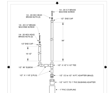 Complete plan for making a 2-meter J-Pole antenna. This drawing in PDF File includes a detailed list of the parts needed to assemble the Jpole antenna for 144 MHz.
 -
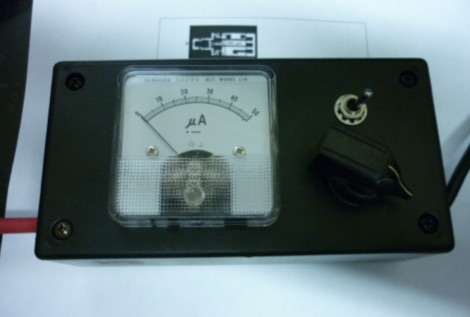 Have you been looking for an easy way to measure power or SWR at 1296 MHz? One thing is certain, it is not easy - simply because the normal range of SWR meters that most of us have is not up to 1300 MHz.
 -
 DF0WD/DL4YHF's Longwave Overview details amateur radio operations on the 135.7 to 137.8 kHz segment in Germany. The author outlines the "inofficial" European band plan, specifying segments for QRSS, TX tests, beacons, conventional CW, and data modes. Early LF activities at DF0WD began with a 20-watt CW transmitter, later upgraded to a homemade linear transverter capable of 100 watts, driven by an Icom IC706 on 10.137 MHz. The station's antenna system includes a 200-meter wire, approximately 10 meters above ground, supported by football field light-masts. Despite its length, the antenna's efficiency is noted as very low due to the immense wavelength of about 2.2 km. The author's experience highlights the significant challenge of achieving effective radiated power (EIRP) on LF, estimating DF0WD's EIRP at around 80 milliwatts based on field strength measurements from PA0SE. DF0WD/DL4YHF has successfully worked numerous countries on 136 kHz CW, including DL, F, G, GI, GM, GU, GW, HB9, HB0, LX, OE, OH, OK, OM, ON, OZ, PA, and SM. The author also mentions ongoing efforts to log contacts with CT, EI, LA/LG, and to complete a two-way QSO with Italy, demonstrating persistent activity on this challenging band.
 -
 A collection of 450 MHz Cheap Yagis that have proven great portable operations, back-packing and transmitter hunts, and are something inexpensive you can throw up in the attic for that weak repeater
 -
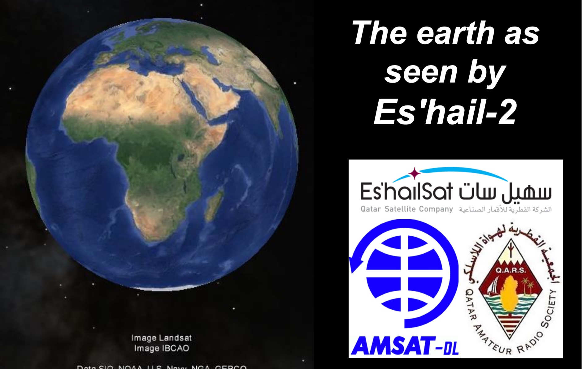 Presentation of the QO-100 the first geostationary OSCAR from Qatar by AMSAT-DL
 -
 Mini-Operating Guide includes useful hints on Using the HM-133 Microphone, Basic Operation, Operating through a Repeater, Programming a Memory Channel and Assigning a Memory Channel to a Memory Bank
 -
 Although most Preselectors are designed with an internal T/R relay, theoretically enabling direct insertion between the transceiver and the antenna, there is a problem when running CW, especially when running full QSK. The switching time of the internal relay is too slow to follow full QSK. The best way to avoid this problem altogether is to insert the Preselector directly into the transceiver’s RX antenna line, thus avoiding entirely the need to switch the Preselector in and out.
 -
 A homemade simple and inexpensive portable antenna support, handy for quick trips to the field and other portable operations
 -
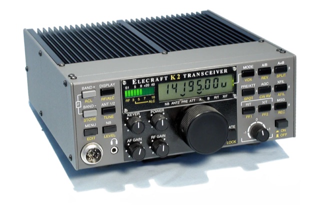
 Clarifies the intricate process of calibrating the _Elecraft K2_ dial, addressing common user challenges and lively discussions on the Elecraft reflector. Wilhelm, W3FPR, dissects the K2's PLL synthesizer design, chosen for its low phase noise, kit-friendly duplication, and cost-effective components. The resource emphasizes the critical role of the 4000.000 kHz reference oscillator's accuracy during CAL PLL, CAL FIL, and CAL FCTR functions, noting its dependence on temperature and crystal stability for optimal performance. Explaining the K2's frequency display, the document reveals it relies on microprocessor-driven look-up tables generated by CAL PLL for VFO values and CAL FIL for BFO values. In SSB and RTTY, these combine, while CW and CWr modes also factor in the sidetone pitch. The author details inherent limitations, such as the 10 Hz increment resolution of the dial and varying PLL step sizes—from 3 Hz on 160 meters to 10 Hz on 10 meters. BFO increments range from 20 to 35 Hz, collectively limiting practical dial accuracy to within **20 Hz** with diligent effort, or **30 Hz** for a slightly less demanding task. The guide outlines a four-step calibration procedure: setting the reference oscillator, running CAL PLL, running CAL FIL, and setting all BFOs. It highlights the _N6KR Method_ as a particularly easy and accurate approach, requiring only the K2 and a known frequency source like WWV for zero-beating, eliminating the need for external test equipment.
 -
 This presentation applies to HF / VHF / UHF antennas and is about 14 different type of antennas suitable for indoor od apartament installations
 -
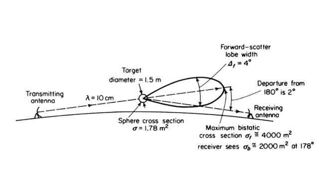 Operating on Airplane scattering. Scattering of radio signals by airplanes. An introduction to operating ariplane scattering, using aircraft to redirect RF that would otherwise be lost in space. Antenna Pointing, Doppler Shift/Digital Modes, using digital modes to operate airscatter.
 -
 Have you ever thought of setting up a portable HF station for an activity like the Field Day ?
 -
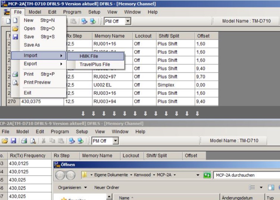 All available frequencies & offsets configurations for repeaters can be downloaded as database for Kenwood MCP-2A memory channel programming software for TM-D710 & TM-V71. Zip file is no more available from the author, but the full table of frequencies is still online
 -
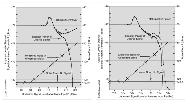 An explanation of the different procedures and definitions that are commonly used for blocking dynamic range (BDR) measurements. Dynamic range in general is the ratio between the weakest signal a system can handle and the strongest signal the same system can handle simultaneously without an operator switching attenuators or turning volume potentiometers
 -
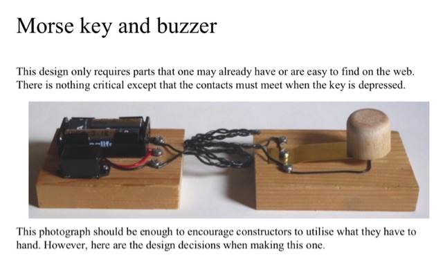 This morse key and buzzer design only requires parts that one may already have or are easy to find on the web. There is nothing critical except that the contacts must meet when the key is depressed.
 -
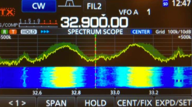 The Icom IC-7300 is a popular SDR transceiver known for its excellent performance in ham bands. However, users have reported issues with reception reliability outside these bands due to ADC aliasing. This phenomenon occurs when the sampling rate of the radio interacts with frequencies outside the intended range, leading to unwanted signals being received. For instance, when tuned between 30 to 36 MHz, users may inadvertently pick up WFM broadcast signals or PMR communications due to aliasing effects. This guide outlines modifications to improve the IC-7300's performance by addressing the low-pass filter design, which is crucial for reducing interference from these unwanted signals. The proposed modifications involve adjusting the low-pass filter on the PA unit to better attenuate frequencies that cause aliasing. Measurements indicate that the original filter design allows significant signal leakage, leading to false receptions. By implementing the suggested changes, users can achieve a notable reduction in unwanted signals, enhancing the overall functionality of the IC-7300. While the modification requires careful soldering, the benefits in performance make it a worthwhile endeavor for serious operators looking to optimize their SDR experience.
 -
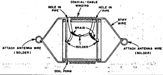 A document that will guide you on Coaxial-Cable trap optimization process to gain on global antenna performance and on increasing effective bandwidth.
 -
 In this post by N6CTA, discover the conversion of the Yaesu ATAS-120A screwdriver antenna for portable use. The author details the creation of two sets of radials, 16 and 32 in 16ft lengths, aiming to optimize the efficiency of ground-mounted antennas. Additionally, insights are shared on attaching male quick disconnect blade tabs, with potential plans for a radial plate kit.
 -
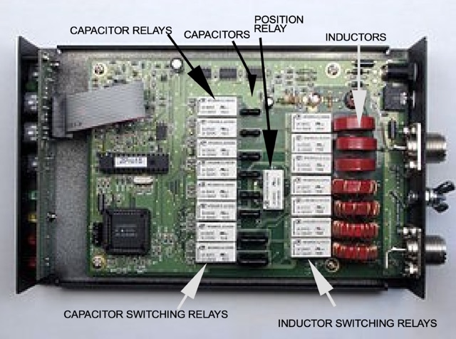 Collection of several topics on antenna tuners and their performance. Why use an antenna tuner? How does an antenna tuner…tune Does an antenna tuner fool the radio? Will an antenna tuner waste power? Can an antenna tuner help get more power to the antenna?
 -
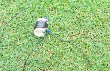
 Experimenting with capacitive antennas for 40 and 80 meters band. A very space-saving antenna with good receivings caracteristics
 -
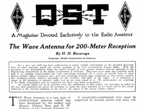 A QST Article published in November 1922 is about the origin of Beverage antennas, an unidirectional antenna type that was discovered and experimented for the first time in that period. This article is the introduction to beverage antenna theory, by the homonimous autho H. H. Beverage.