Search results
Query: wave
Links: 989 | Categories: 55
Categories
- Antennas > End-Fed > End Fed Half Wave Antenna
- Operating Modes > Longwave
- Antennas > Longwave
- Manufacturers > Microwave
- Shopping and Services > Microwave
- Operating Modes > Microwave
- Antennas > Microwave
- Shopping and Services > Antennas > Microwave Antenna
- Manufacturers > Antennas > VHF UHF Microwave > Microwave antennas
- Technical Reference > Mircrowave
- Software > Shortwave
- Antennas > Shortwave
- Shortwave Radio
- Manufacturers > Antennas > VHF UHF Microwave
- Technical Reference > Standing Wave Ratio
- DX Resources > Beacons > 10 GHz Beacons
- Antennas > 40M > 40 meter Loop Antennas
- Operating Modes > Aircraft scatter
- Manufacturers > Antennas
- Radio Scanning > Regional > Australia
- Shortwave Radio > BCL Resources
- DX Resources > Beacons
- Shortwave Radio > Beginner's guides
- Shortwave Radio > Broadcasters
- Manufacturers > Broadcasting Equipment
- Shortwave Radio > Clubs
- Manufacturers > Antennas > VHF UHF Microwave > Discone Antennas
- Antennas > End-Fed
- Manufacturers > Antennas > VHF UHF Microwave > Ground Plane Antennas
- Antennas > Horn
-
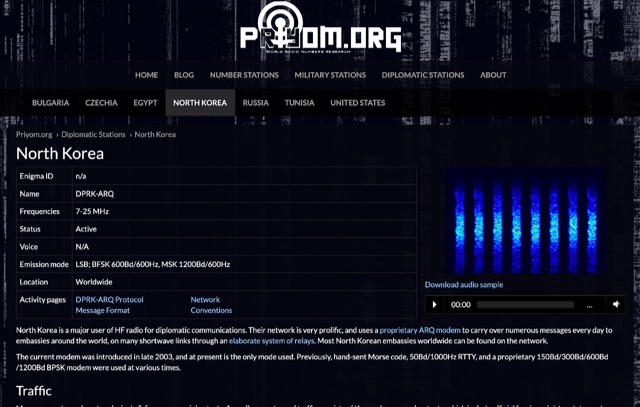 The resource details active HF radio networks maintained by foreign ministries for diplomatic communications, specifically listing operational schedules and frequencies. It currently covers networks for Bulgaria, Czechia, Egypt, North Korea, Russia, Tunisia, and the United States. The content provides specific operational parameters for these government-run shortwave stations. Information includes details on _legacy modes_ of operation and specific transmission times. The site also includes schedules for various _number stations_ which often utilize similar HF spectrum allocations. The data presented aids in identifying and monitoring these unique, non-amateur radio signals across the shortwave bands. Specific sections are dedicated to the networks of North Korea and the United States, offering granular data for each.
 -
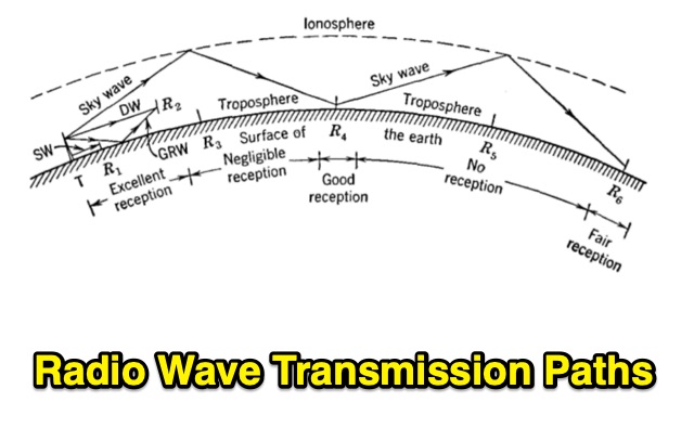 Radio transmission is affected by the presence of the earth. Also, the upper atmosphere of the earth is a rarefied, ionized, conducting region that influences transmission considerably. Undertanding Wave Diffraction, Wave Refraction and Absorption
 -
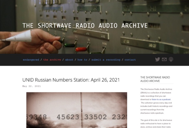 From the sortwave radio audio archive, a collection of recordings of several spy numbers stations, russian, spanish, cuban audio recordings
 -
 A DIY cantenna can extend your WiFi range by building a 2.4 GHz high-gain antenna using accessible materials. The design, based on waveguide principles, uses a cylindrical tube to capture WiFi signals and can even connect to access points half a mile away in ideal conditions. While the ideal tube diameter was hard to find, a 4-inch aluminum dryer vent was chosen despite theoretical limitations. The cantenna offers a cost-effective, functional boost for your wireless network.
 -
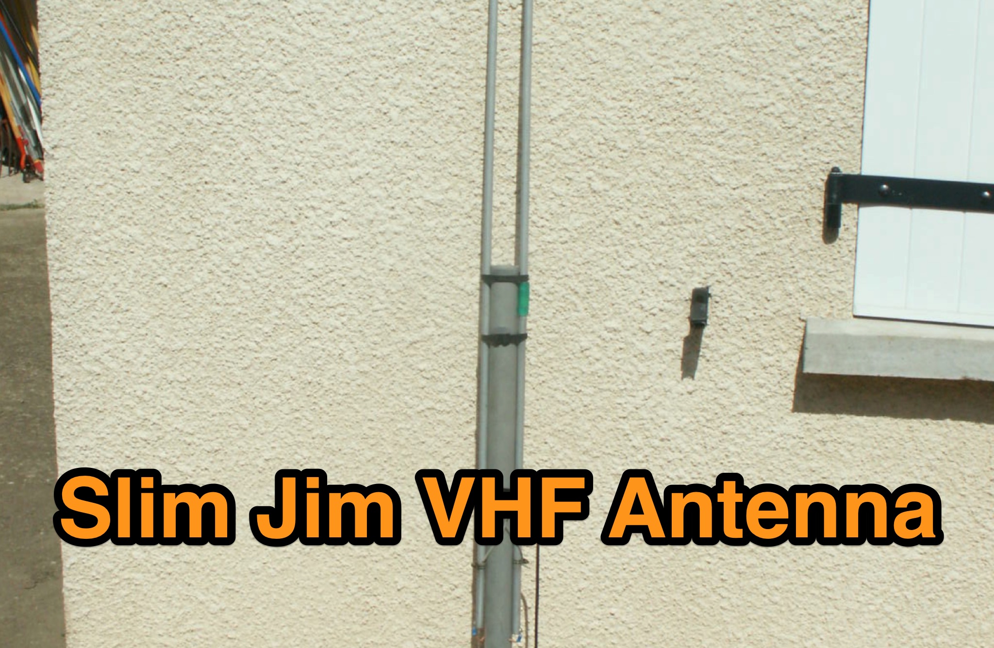 The Slim Jim VHF antenna, originally designed by G2BCX, is a folded half-wave dipole fed by a quarter-wave matching section. This version, built from a recycled professional aluminum dipole, demonstrates that various materials—such as copper, brass, or twin-lead—can be used. The article details the antenna’s construction, required materials, and tuning process, emphasizing mechanical stability and ease of assembly. With proper adjustment of the feed point, it provides excellent SWR across the band. Its durability and simplicity make it a practical and efficient VHF antenna solution.
 -
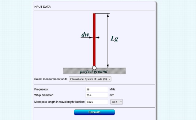 A 5/8 λ antenna, often thought to be ideal for all frequencies, has unique characteristics that don't universally apply. First introduced for medium-wave radio, it works optimally at 225° antenna length over ideal ground, yielding high efficiency. However, at VHF and higher frequencies, it offers no advantage over other antennas due to real ground conditions and complex matching requirements. DIY calculators provide only rough estimates, useful as a starting point for simulations, not for precise builds.
 -
 7MHz to 30MHz operation is achieved with a magnetic-mounted HF antenna designed for car roof deployment, capable of handling 100 Watts without an external antenna tuner. The design incorporates a large base-loading coil with multiple taps, allowing for frequency selection across various HF bands. This coil effectively increases the electrical length of a short telescopic antenna element, compensating for its inherent capacitance. Construction involves 3D-printed components for the coil former and support structures, though conventional building methods using plastic drainpipes are also suggested. The car body serves as the ground plane, with the coil assembly mounted on a 500mm square metal plate secured by super neodymium magnets. Protection under the magnets is advised to prevent vehicle scratches. Detailed instructions cover winding the 30-turn coil with 2.5mm diameter household electrical cable, assembling the 3D-printed parts, and making soldered connections. Taps are staggered every five turns for precise frequency adjustment. Performance examples include a 7913km contact to Japan using a 1.5m element and 100 Watts, demonstrating low-angle radiation and omni-directional pattern with minimal S-point loss compared to a full quarter-wave.
 -
 Andrew Georgakopoulos, SV1DKD, modeled the End-Fed Half Wave (EFHW) antenna using MMANA-GAL software. He evaluated the EFHW-8010-2K from Myantennas.com for field operations, comparing it to random wires, OCFD, and dipole antennas. His results showed similar performance to OCFD, confirming EFHW's practical feeding advantage but with potential high-voltage risks at the feed point
 -
 Direct conversion receivers (DCR) are gaining renewed interest due to advancements in semiconductor technologies and their suitability for integration in compact, low-cost, multi-standard applications. Unlike traditional superheterodyne receivers, DCR eliminates image frequencies and bulky off-chip filters but introduces challenges like DC offsets, nonlinearity, and noise issues. This tutorial explores DCR's historical development, compares it with other receiver architectures, and addresses its inherent obstacles. DCR's potential for integration and compatibility with software-defined radio highlights its role in modern communication systems despite its technical complexities.
 -
 This article explores the revival of the classic 3 Transistor Short Wave Radio kit originally offered by Radio Shack in the late 1960s. Updated with modern silicon transistors and components, the design retains its educational charm while enhancing performance. Detailed assembly instructions and illustrations are provided to facilitate replication. The project not only pays homage to nostalgic electronics but also serves as a practical introduction to radio theory, including modulation techniques and receiver types, fostering a hands-on learning experience for enthusiasts.
 -
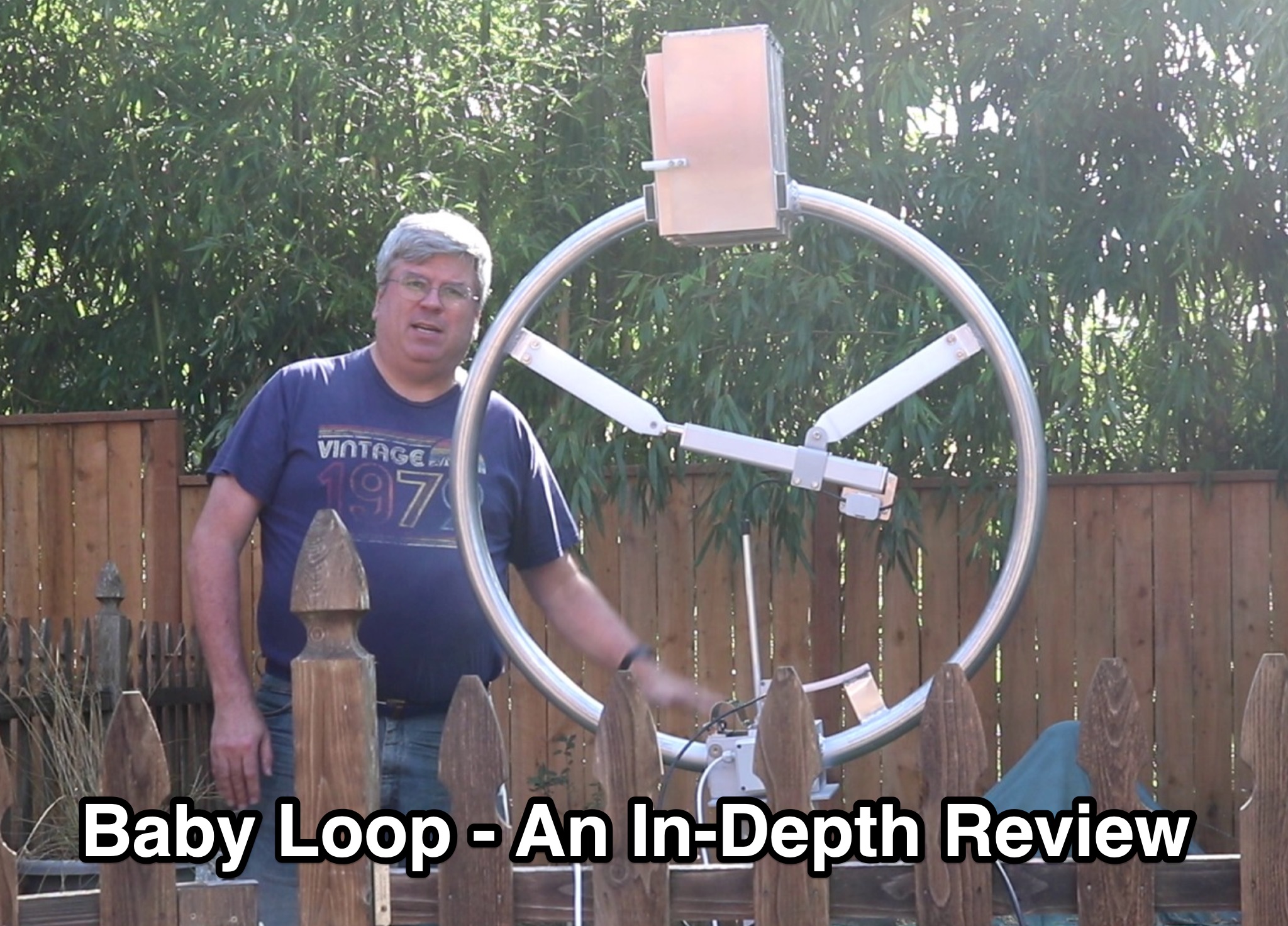 This article provides an in-depth review of the Ciro Mazzoni Baby Loop Ham Radio Antenna. The author, a ham radio operator, compares this magnetic loop antenna with his usual End Fed Half Wave antenna, discussing the performance and installation considerations. The post explains the concept of loop antennas, resonating frequencies, and the benefits of using a small loop antenna with a capacitor for optimal operation. If you are looking for information on magnetic loop antennas and their effectiveness in restricted spaces, this review offers valuable insights and practical experiences for ham radio operators.
 -
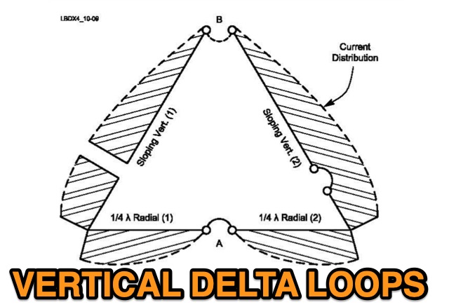 A vertical delta loop is a practical antenna for low bands, popular for its simple design requiring just one support. Its shape, an equilateral triangle in free space, yields optimal gain and radiation resistance. Deviating from this shape lowers performance. The delta loop can be polarized either horizontally or vertically based on the feed point location. In vertical polarization, it acts as two quarter-wave verticals with the baseline feeding one side. This design minimizes radiation from the baseline while maintaining effective operation.
 -
 SWList iOS App, provides access to the EiBi list for discovering and identifying shortwave radio stations, curated by Eike Bierwirth. It offers four search methods: by frequency, radio band, station name, or language. Users can view detailed station information and map locations if available, with support for both light and dark modes.
 -
 Antenna patterns are all about interference. Presentation on wire antennas for HF bands. Dipoles, horizontal and vertical dipoles, effects of ground on radiation patterns, multi-band wires antennas. Knowing what you should expect from the radiation patterns for waves on your wires will help you choose what will work best for your needs. The principles of interference can lend insight into what to expect from a wire antenna.
 -
 This page delves into the debate surrounding the End-Fed Half-Wave (EFHW) antenna, exploring whether it is truly a multiband antenna without the need for a tuner. The author investigates the claims and criticisms surrounding these popular antennas, discussing their resonance on various bands and their efficiency for DXCC achievements. The content is valuable for hams interested in understanding the capabilities of EFHW antennas and their performance across different HF bands, with a focus on practical usage and real-world results.
 -
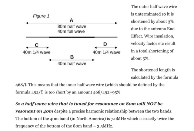 A half wave wire that is tuned for resonance on 80m will NOT be resonant on 40m despite a precise harmonic relationship between the two bands. The End Effect is caused by a capacitive coupling between an unterminated wire end and the ground.
 -
 The tri-band trapped delta loop antenna design operates on 80 meters (3.5–4 MHz), 40 meters (7–7.3 MHz), and 30 meters (10.1–10.15 MHz) using a single triangular wire loop. This configuration eliminates the need for an external antenna tuner or band-switching relays. The antenna's physical perimeter, approximately 270 feet, establishes 80M as the fundamental band, with specific trap placements enabling resonance on 40M and 30M. Trap design and placement are critical, with 30M traps positioned inboard of 40M traps within the horizontal element. Each slant leg measures approximately 80 feet. The resource references foundational information from the _ARRL Antenna Handbook_ and _ON4UN’s Low Band DXing_ regarding full-wave loop behavior and feedpoint impedances. The project aims to provide multi-band HF operation from a single, fixed antenna structure.
 -
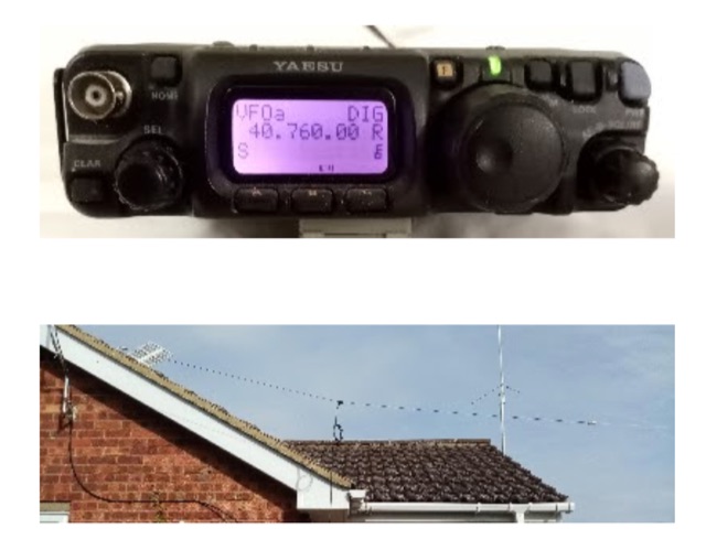 The 8m ISM band, a unique frequency range between 10m and 6m, holds potential for amateur radio enthusiasts, yet it remains largely unallocated. This spectrum offers fertile ground for research and self-training. The author's experience with low-power transmissions and WSPR testing highlights the band's capabilities and the need for a narrow, speech-free amateur allocation to encourage experimentation. Discover the world of 8m ISM radio exploration and its future possibilities.
 -
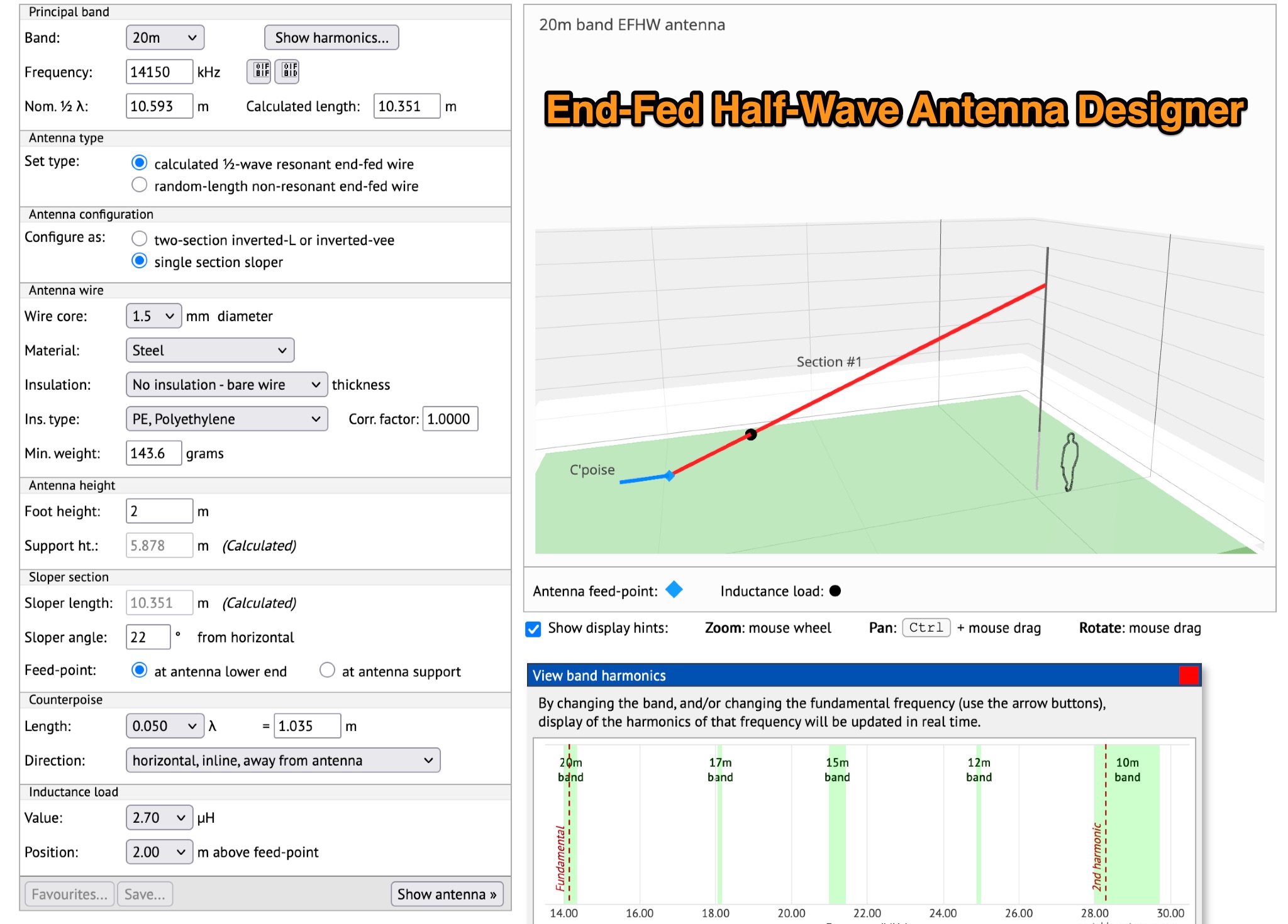 This page provides guidance on designing an End-Fed Half-Wave (EFHW) or Random-Length antenna for amateur HF bands, such as 80 or 40 meters. The content explains how to optimize the antenna for multi-band use and match it to a 50-ohm system using an unun. Hams can generate radiation patterns, VSWR charts, and antenna current diagrams for their customized antenna designs. Understanding how antenna dimensions affect performance is essential for successful field operations. The page caters to ham radio operators looking to build efficient and effective HF antennas for their stations.
 -
 Wavelog, a web-based amateur radio logbook application, launched in February 2024, represents a significant fork from the established Cloudlog platform, developed by a core team including DF2ET and DJ7NT. This open-source project focuses on delivering advancements in both stability and functionality, specifically tailored for the amateur radio community. The application allows users to manage their radio logs from diverse environments, including professional servers, standard web hosting, or even compact _Raspberry Pi_ setups. The platform distinguishes itself through its emphasis on simplicity, robust features, and versatile accessibility, enabling operators to log contacts from virtually any location. It supports various operating modes and data formats, providing a flexible solution for tracking QSOs and managing station activities. The project's development is driven by the collaborative spirit of the amateur radio community, prioritizing utility and user experience over commercial objectives. Key features include comprehensive logging capabilities, support for multiple bands and modes, and integration with common amateur radio data standards, ensuring broad utility for DXers and contesters.
 -
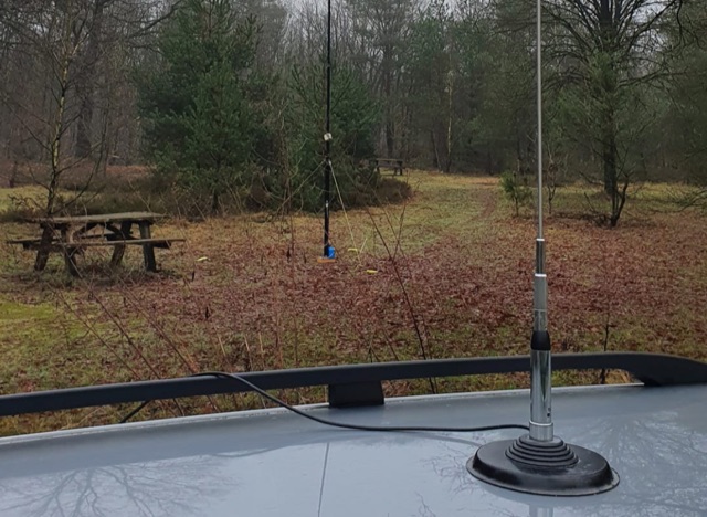 PH0NO conducted field tests comparing a mobile antenna (DX-UHV) to an end-fed half-wave wire. Results on 20m showed the end-fed wire outperforming the mobile antenna, with a significant difference in signal strength. On 40m, the end-fed wire surpassed the mobile antenna in spots and reach. While the mobile antenna is more practical, the end-fed wire offers superior performance. Further testing is planned.
 -
 This resource details the construction and performance of a compact broadband magnetic loop antenna designed for portable receiving applications with devices like the _ATS MiniRadio_. The antenna utilizes approximately 3 meters of 0.5–1 mm copper wire wound in two turns on a rhomboidal wooden frame, measuring 50 cm by 70 cm. It connects via a modified 9:1 unun, where the primary center tap is isolated from ground to improve common-mode noise rejection. The design provides untuned operation across a frequency range from the longwave band up to approximately 25 MHz. Performance characteristics include observable directivity for noise suppression and the ability to connect directly to a radio or via a 50 coaxial cable for remote operation. The article specifies the unun's 3:1 turns ratio and its SMA output for connectivity. The methodology focuses on practical construction and observed reception quality.
 -
 Manufacturer of 50MHz, 70MHz, 144MHz, 222MHz, 432MHz, 900MHz or 1.2GHz transverters and VHF UHF amplifiers
 -
 Addresses the common challenge of constructing effective dual-band antennas for VHF/UHF operations, specifically detailing a J-pole design. It covers the theoretical underpinnings, including calculations for quarter-wavelength radiator and stub sections, accounting for velocity factor and design frequency. The resource provides practical construction guidance using readily available materials like TV twin lead and coaxial cable, culminating in an antenna with a total length of approximately 52 inches. Performance metrics are presented, showing a measured SWR of 1.7:1 or better across most of the 2-meter band and less than 2:1 across the 70-cm band. These SWR measurements, referenced to 50-ohm impedance, were taken at the transmitter end of the feed line. The article also touches upon the necessity of a balun for proper impedance matching between the balanced J-pole and unbalanced coaxial feed line, suggesting a split-core cylindrical ferrite for this purpose.
 -
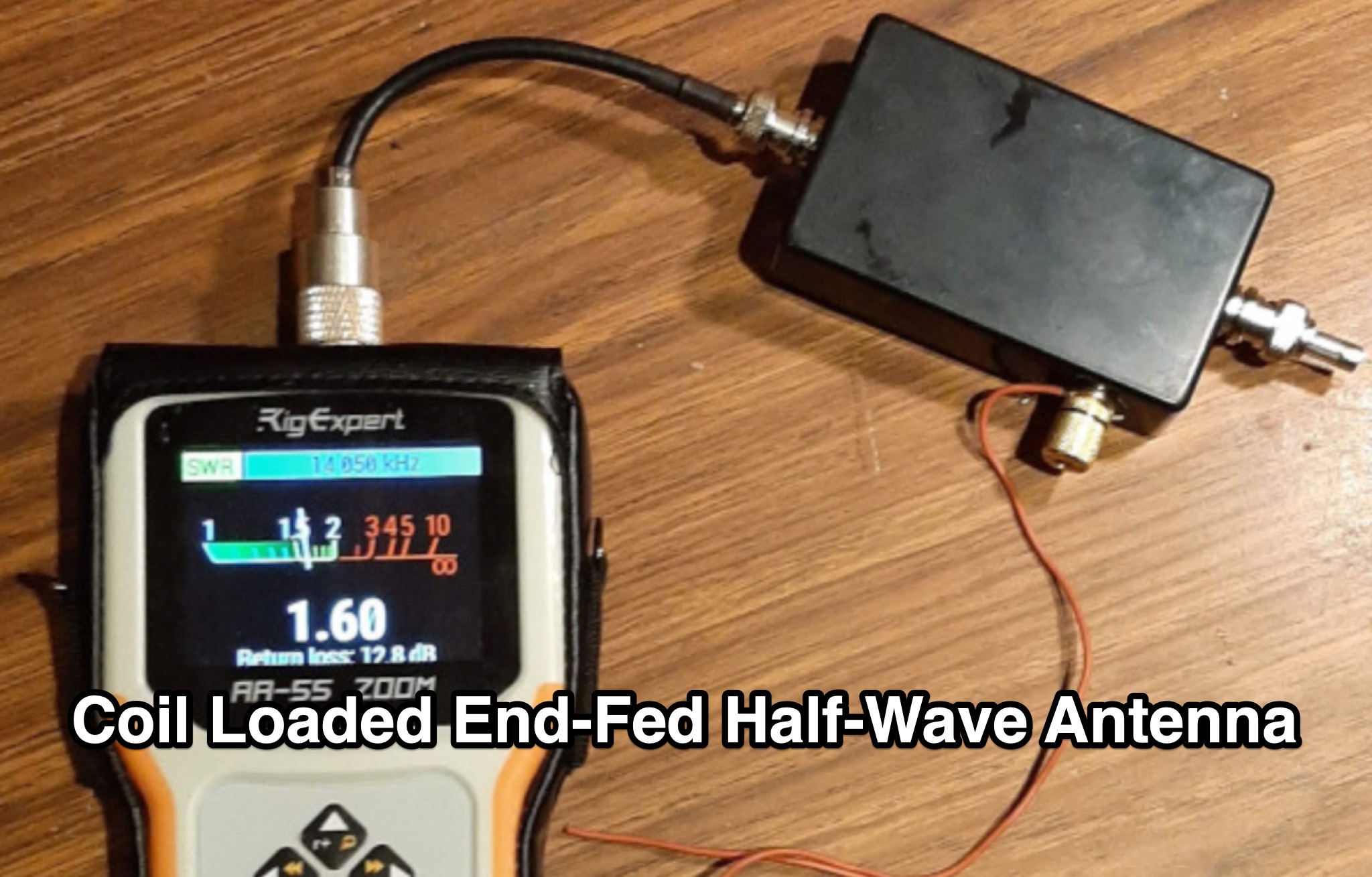 This page discusses the CLEFHW (Coil Loaded End-Fed Half-Wave) antenna, a portable variation of the popular EFHW design for ham radio operators. The article explains how the CLEFHW allows for backpack portable operation without the need for trees or poles, making it ideal for POTA activations and rapid deployment scenarios. The author details the design, optimization for 20m band, and compares efficiency to full-length wire antennas. Suitable for hams interested in portable antenna solutions and quick setup options for amateur radio activities.
 -
 The 1/4 wavelength vertical antenna project, initially designed for 20 meters, has evolved into a versatile portable solution covering 10 through 60 meters. K0BXB details its construction, emphasizing a bottom-loaded design with a tapped loading coil and four 10-foot counterpoise wires. The author shares personal experiences and field results, including **18 QSOs** during a park activation on 17m and 30m with 10 watts, and a **2,435-mile** contact with a contest station in Bonaire on 20m using 5 watts. Comparisons are drawn to commercial offerings like the _Wolf River Coils TIA_ and _QRPGuys Triband Vertical_, highlighting the DIY antenna's small footprint, light weight, and ease of tuning for POTA activations. The resource includes insights into using test equipment such as the _NanoVNA_ for SWR optimization and discusses various radiator lengths, from 17-foot wire to a 102-inch whip, demonstrating adaptability for different portable setups. Construction tips cover coil winding, tap placement, and connecting feedlines and radials using common components.
 -
 WB5NHL describes setting up a 160-meter antenna on a small suburban lot, where standard options like Beverage antennas and 1/4 wavelength verticals require extensive space and ground systems. Instead, Guy Olinger's Folded Counterpoise (FCP) provides a solution. The FCP minimizes ground losses by using a folded wire design, allowing effective antenna placement in limited space. The FCP, fed with an isolation transformer, enabled WB5NHL's first 160-meter antenna installation, offering improved performance despite space constraints.
 -
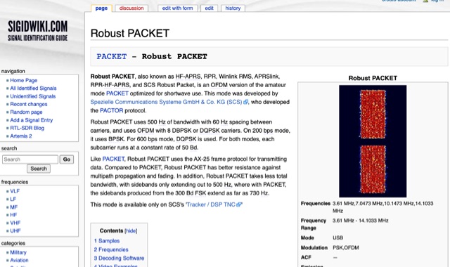 Robust PACKET, developed by Spezielle Communications Systeme GmbH & Co. KG (SCS), is an OFDM variant of the amateur PACKET mode specifically engineered for HF operation. This mode utilizes a 500 Hz bandwidth with 60 Hz carrier spacing, employing OFDM with 8 DBPSK or DQPSK carriers. It supports 200 bps using BPSK and 600 bps with DQPSK, with each subcarrier operating at a constant rate of 50 Bd. Robust PACKET leverages the AX-25 frame protocol for data transmission, similar to standard PACKET. Compared to traditional PACKET, Robust PACKET demonstrates enhanced resilience against multipath propagation and fading effects, critical for reliable HF communications. It also exhibits a more efficient spectral footprint, with sidebands extending only to 500 Hz, whereas 300 Bd FSK PACKET can produce sidebands up to 730 Hz. Operational frequencies for Robust PACKET include 3.61 MHz, 7.0473 MHz, 10.1473 MHz, and 14.1033 MHz, with specific regional frequencies also documented. Decoding software options for Robust PACKET include Wavecom W-Code and Wavecom W-Spectra. The mode is primarily supported by SCS's 'Tracker / DSP TNC' hardware.
 -
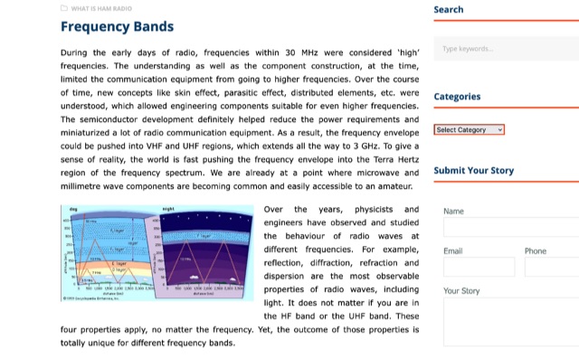 During radio's early days, high frequencies were under 30 MHz due to technical limitations. As understanding grew, components improved, allowing for higher frequencies like VHF and UHF up to 3 GHz. The HF band's long wavelengths provide unique propagation challenges influenced by solar activity. VHF and UHF bands face diffraction and reflection issues but offer diverse applications, from amateur radio to 5G and GPS technologies.
 -
 This article focus on the radiation angle of vertical antennas and the fundamentals of electromagnetic wave propagation. The calculation of antenna length at 145 MHz is followed by an explanation of electromagnetic wave speed and the link between wavelength, frequency, and velocity. Author discusses the 5/8th wave vertical antenna, namely its performance and the influence of radiation angle on signal transmission. Figures and analogies demonstrate how different antenna types produce distinct radiation patterns. This highlights the importance of selecting the right antenna for a certain purpose, such as local traffic or dxing. The article discusses a variety of factors that affect antenna performance, including SWR, propagation conditions, and equipment dependability
 -
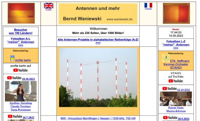 A large archive of medium-wave and long-wave broadcasting antennas from all over the world
 -
 This PDF file provides detailed information on HF propagation for ham radio operators. It covers the principles of how radio signals travel over long distances, including factors that affect signal strength and propagation. The content is useful for hams looking to improve their understanding of radio communication and optimize their transmissions. Whether you're a beginner or an experienced operator, this resource offers valuable insights into HF propagation that can enhance your communication skills and efficiency on the airwaves.
 -
 This article presents a novel Top Loaded End-Fed Half-Wave (TLEFHW) antenna design for 20-meter ham radio operation. The antenna features a compact 14-foot vertical radiator with a capacitance hat configuration, eliminating the need for radials or ground systems. Using EZNEC modeling and field testing, the design achieves a 1.5:1 SWR across the 20m band with a 4.11 dBi gain. Key features include quick deployment, lightweight construction, and directional radiation pattern with 110-degree beamwidth. The design, while requiring a 45-foot footprint due to the top hat, offers an effective portable solution for amateur radio operators seeking a no-ground, no-tuner 20m antenna option.
 -
 WaveTalkers asked AI itself what it thought. All of the content in the WaveTalkers AI Resources section is generated by AI. From the content to the code itself they will make every effort to showcase what works and what doesn't along the way.
 -
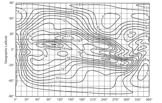 Come learn why it is very difficult to predict propagation on the top band. Ionospheric Variability, Time Variations of Ionospheric Parameters, Atmospheric Gravity Waves, Ionospheric Absorption and The Role of Negative Ions.
 -
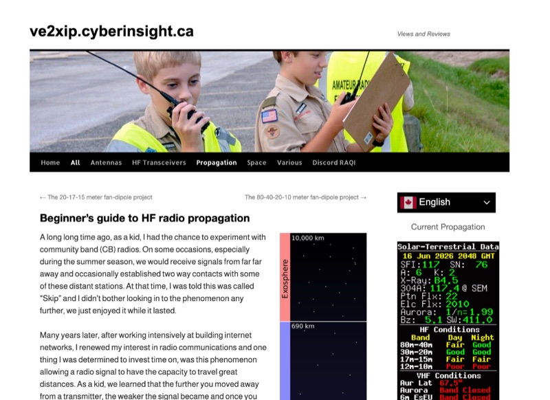 High Frequency (HF) radio propagation, particularly the phenomenon of "Skip," which enables long-distance radio contacts, is thoroughly explained for newcomers to the amateur radio hobby. The article begins by defining essential terms such as _radio signal_, atmosphere, troposphere, stratosphere, mesosphere, thermosphere, exosphere, and aurora, setting a foundational understanding for subsequent discussions. A significant portion of the content focuses on the ionosphere, identifying it as the primary driver of HF propagation. Its structure, including the D, E (E1, E2, E3), and F (F1, F2) layers, is detailed, along with how solar radiation influences these layers to refract radio waves back to Earth. The concept of "The band is opened!" is introduced, specifically noting refraction around **21 MHz**. The guide also touches upon ground waves, space waves, and temperature inversions affecting VHF/UHF propagation, contrasting them with the dynamic nature of ionospheric HF propagation. Factors like antenna polarization, takeoff angle, and the sun's solar cycle are mentioned as critical influences on signal path, with examples like 80-meter band propagation after sunset and 40-meter/20-meter bands offering near-constant propagation.
 -
 Understanding radio wave propagation is fundamental for effective HF communication, and this guide from the Galway Radio Club elucidates the principles behind _Near Vertical Incidence Skywave_ (NVIS) operation. It begins by contrasting NVIS with line-of-sight and surface wave propagation, highlighting its utility for reliable regional coverage, particularly in challenging terrains or within the skip zone. The document explains how NVIS leverages high-angle radiation, refracting signals from the ionosphere to return to Earth within a circular region, typically up to **650 km** (400 miles) from the transmitter. The guide delves into critical factors influencing NVIS, such as the _critical frequency_ (Fo) and the Maximum Usable Frequency (MUF), emphasizing their dependence on solar activity, time of day, and season. It provides practical advice on frequency selection, noting that 40 meters is often the highest daytime NVIS band, with 60 meters and 80 meters favored as darkness falls. The author, EI5DD, suggests using an ionogram for real-time propagation data, considering it more reliable than generic ham-clocks. Antenna considerations are also covered, recommending dipoles, inverted vees, or phased dipoles positioned 0.1 to 0.25 wavelengths above ground for optimal high-angle radiation. The document mentions mobile NVIS setups, including military configurations and commercial options like the Barrett Communications roof-rack antenna, which can cost around **£2000.00**. It concludes by reinforcing NVIS as an essential technique for national emergency communications, with 5 MHz (60m) and 80 meters being primary bands for daytime and nighttime operations, respectively.
 -
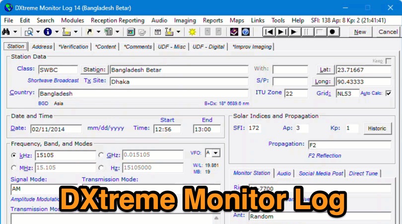 Demonstrates the capabilities of DXtreme Monitor Log 14, a specialized software application designed for radio spectrum monitoring and logging. The resource details its core functionality, which includes logging stations across various bands and supporting multiple transmission modes such as AM, CW, FM, LSB, USB, and RTTY. It highlights features like the ability to select country formats for new databases and the **Schedule Checker** tool, which assists users in identifying broadcast stations for monitoring. The software facilitates tracking **Maidenhead grid squares**, particularly useful for VHF and UHF monitoring activities. It also supports QSL management and offers tools for efficient contact logging, catering to both amateur radio operators and shortwave listeners. Specific information includes its version number, Monitor Log 14, and its utility for DXers and other radio enthusiasts in managing their monitoring experiences and logging contacts effectively.
 -
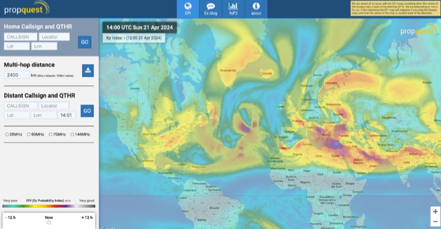 This website explains signal variations on a local radio net by tracking the foF2, a measure of ionosphere's ability to reflect radio waves. The website shows daily foF2 variations and how it affects Near Vertical Incidence Skywave (NVIS) propagation for local nets. It also considers D-layer absorption affecting lower bands and F2 MUF distance for long-distance communication. Additionally, the website tracks foEs for E-layer propagation and an EPI index for predicting Es chances.
 -
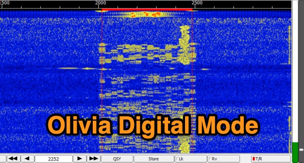 The Olivia digital mode, a **Multi-Frequency Shift Keying (MFSK)** radioteletype protocol, is specifically engineered for robust communication under difficult propagation conditions on shortwave radio bands from 3 MHz to 30 MHz. Developed by Pawel Jalocha in 2003, Olivia signals can be decoded even when the noise amplitude exceeds the digital signal by over ten times, making it highly effective for transmitting ASCII characters across noisy channels with significant fading and propagation phasing. Early on-the-air tests by Fred OH/DK4ZC and Les VK2DSG on the Europe-Australia 20-meter path demonstrated intercontinental contacts with as little as one-watt RF power under favorable conditions. Common Olivia modes are designated as X/Y, where X represents the number of tones and Y is the bandwidth in Hertz, with examples including 8/250, 16/500, and 32/1000. The resource clarifies that Olivia, unlike some other digital modes, produces a constant envelope, allowing RF power amplifiers to achieve greater conversion efficiencies and making it less prone to non-linearity. Operators are advised that **Automatic Level Control (ALC)** can be set higher than no meter movement for MFSK modulation, as long as it's not driven past its high limit, contrary to common misinformation about other digital modes. The Olivia community encourages voluntary channelization on suggested calling frequencies, such as 14.0725 MHz for 8/250, to facilitate initial contacts, especially for signals below the noise floor. The Olivia Digital DXers Club provides links to Groups.io, Facebook, and Discord for community engagement and offers details on QSO parties.
 -
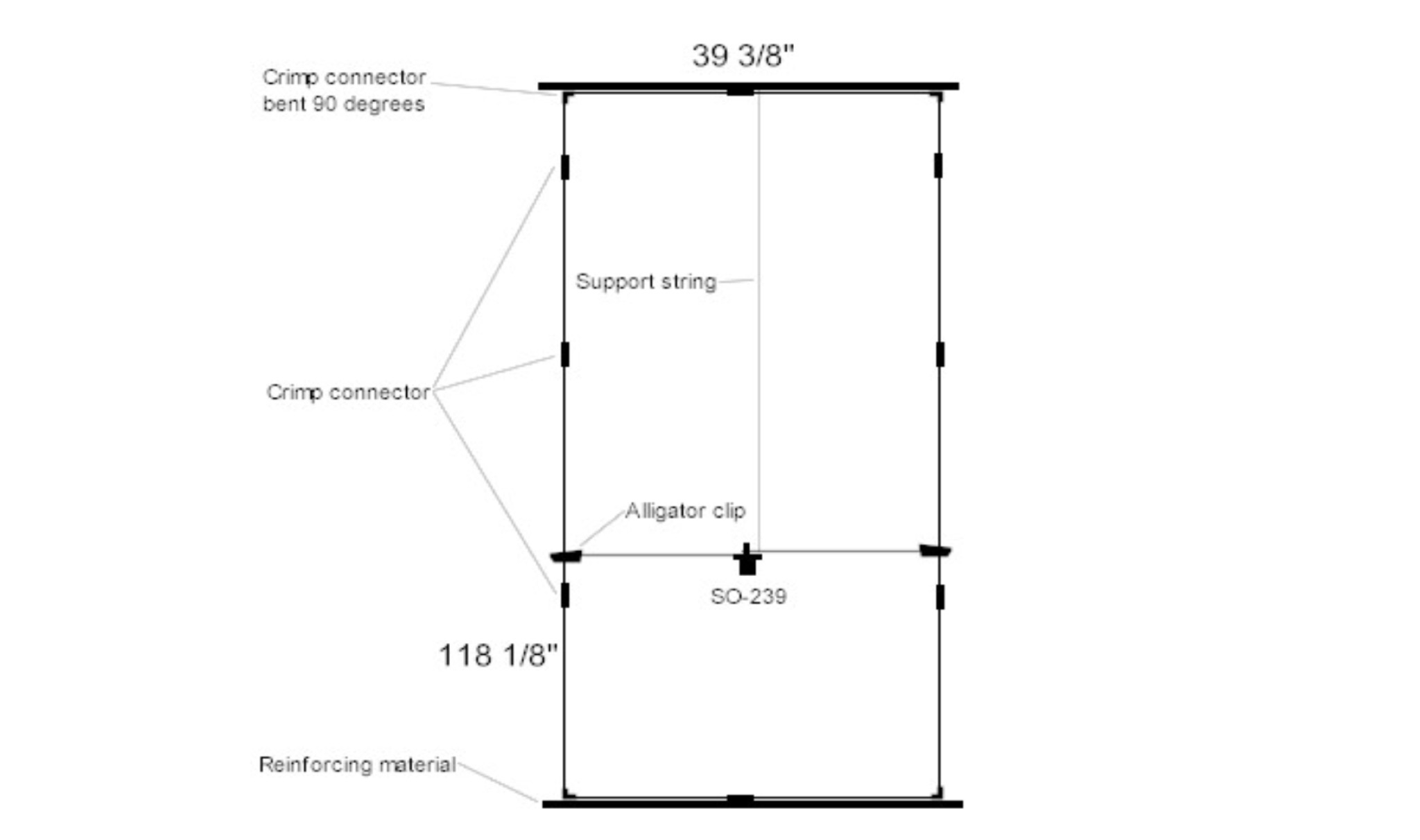 The K5USS 6 Meter Hentenna Project page on Hamuniverse provides detailed instructions on how to build a 6 meter directional antenna with 3.5 dBd gain. The project is presented with permission from K5USS, Charlie of Richardson, Texas. This directional antenna is a full wave loop on 6 meters, horizontally polarized but mounted vertically, with a 50 ohm impedance, ideal for 6 meter SSB operations. The page is useful for hams looking to construct their own directional antenna for improved performance on the 6 meter band.
 -
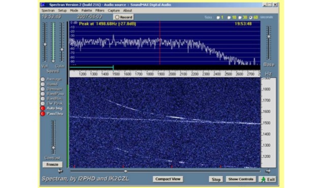 Getting started with Aircraft scatter, defined as the process of scatter radio waves of the body of a traveling aircraft in order to enhance the distance possible to bridge on VHF, UHF and microwaves. The ACS path, Equipment requirement and Operating techniques
 -
 Details the installation and operation of the DX Engineering TFS Series Transmit Four Square System Phasing Units, specifically models like the DXE-TFS4-160B, DXE-TFS4-80B, and DXE-TFS4-40B. It covers system components, required parts, and a discussion of vertical antenna selection, including a table of suitable DX Engineering Monoband Vertical Antennas. Installation procedures are outlined, encompassing site selection, four square layout, topographical considerations, and noise source mitigation. Specific instructions are provided for mounting the phasing unit, antenna feedline connections using 1/4-wave 75-ohm coaxial cables, and control wire routing. The document also includes details on radial system implementation, with a table of radial wire lengths for 160, 80, 75, and 40 meters, and procedures for tuning the vertical antennas for optimal performance. Operational aspects of the Four Square Control Console are described, including front and rear panel functions, control logic (Table 4), and typical transceiver/amplifier interconnections. The system enables directional control with approximately 5 dB gain over a single vertical element in four directions or an omni-directional pattern, achieving typical front-to-back ratios exceeding 20 dB. Lightning protection and initial system testing are also addressed, along with a 5 kW CW and 10 kW PEP SSB power rating and hot switching lockout feature.
 -
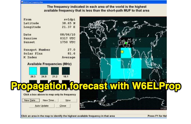 In 2004, Carl Luetzelschwab, K9LA, wrote a guide on using W6ELProp for radio wave propagation predictions. This tutorial, translated for broader accessibility, explains initial setup, configuration, and daily use. It emphasizes using mean solar index values for accuracy, helping users effectively predict and interpret propagation for improved amateur radio operations.
 -
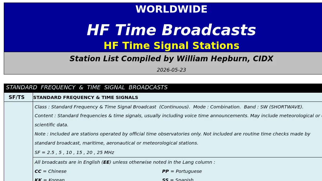 The resource details HF time broadcast stations, categorizing them into "Standard Frequency & Time Signal Broadcast" and "Time Signal Broadcast" types. Standard Frequency & Time Signal Broadcasts, like those on **2.5 MHz** and **5 MHz**, originate from official time observatories and offer continuous standard frequencies, time signals, and often voice announcements, potentially including meteorological data. These stations operate in the SW band. Time Signal Broadcasts also provide continuous time signals, typically with voice announcements, but without the strict observatory origin requirement. The list includes specific frequencies such as 3.33 MHz, 4.996 MHz, 7.85 MHz, 9.996 MHz, 14.67 MHz, 14.996 MHz, 15.006 MHz, and 20 MHz, alongside the primary standard frequencies. Each entry specifies the station's ID time, call sign, geographic coordinates, and operational notes, including languages like _English_, Chinese, Portuguese, Korean, and Spanish. Some entries also indicate decommissioning dates, such as the station on 3.33 MHz scheduled for 2026-06-22.
 -
 Presents DJ5IL's personal amateur radio station, detailing his journey as a licensed operator since 1973. The resource covers his **shack setup**, including an Elecraft K4D, Icom IC-7610, and various vintage transceivers like the Drake 2-B, along with a SPE Expert 1K-FA amplifier. Antenna systems include a PRO.SIS.TEL RD1524T rotary dipole for 40/20/15/10m at 15m height, an 18m vertical dipole with an SGC SG-230 tuner for 3.5-30 MHz, and an inverted-V dipole for 80m. The site features a **QSL gallery** showcasing his custom card designs and outlines his QSL policy, emphasizing the exchange of unique, personalized cards over generic confirmations. It also includes a detailed operator's biography, tracing his early fascination with radio, obtaining his license at 16, and memorable QSOs, such as a contact with his blood-relative W3NZ. The resource also delves into the historical significance of amateur radio's role in pioneering shortwave communication following the 1912 International Radiotelegraph Convention, which initially relegated amateurs to wavelengths of 200 meters and shorter. DJ5IL's philosophy on "ham spirit" is discussed, stressing the unpolitical nature of amateur radio as a global fraternity.
 -
 A full-wave delta loop antenna, approximately 141 feet in total wire length for the 40-meter band, offers a low angle of radiation, which is highly advantageous for DX operations. This design, optimized for both 30m and 40m, leverages a specific circumference calculation of 1005/F, ensuring resonance on both bands through a simple switching mechanism. The antenna's configuration enhances long-distance communication, making it a practical choice for hams with limited space. The resource details the construction process, including the use of a _Ceramic Knife Switch_ for band selection and an _RG-11_ matching section to achieve optimal impedance. It outlines the precise loop lengths required for each band, along with tuning secrets to ensure efficient operation. Requiring a minimum height of 12 feet, this antenna can be supported by a single mast or tree limb, making it suitable for suburban installations where stealth or space constraints are a factor.
 -
 When installing a mobile antenna, optimal placement significantly impacts performance. Factors such as gain, antenna type, ground plane availability, mounting style, and environment must be considered. Antenna designs, such as 1/4 wave and 5/8 wave, have distinct radiation patterns ideal for specific settings—urban areas or flat terrains, respectively. Ground plane size requirements differ by frequency, impacting effectiveness. Among vehicle mounting options, the car roof center provides the best ground plane and minimal obstruction, ensuring peak performance, especially at higher frequencies like 800 MHz.
 -
 Designing a collapsible 6-meter beam antenna involves careful consideration of element geometry and feedline matching, as demonstrated by VE3SMA's project. The construction draws inspiration from foldable dipole concepts and established wire beam designs like the Penn. State 40m beam and the DJ4SA Spiderbeam. Utilizing **4NEC2 modeling**, the author optimized element lengths for gain and bandwidth, observing the impact of end loops on resonant frequency and the need for compensation. Feeding the approximately 25-ohm balanced antenna with 50-ohm unbalanced cable required a specialized network. This setup incorporates a choke **balun** and a matching section built from two series quarter-wave transformers using readily available 75-ohm cable. On-the-air results validate the design, including a successful 1st double hop Es QSO with 10 Watts and satisfactory performance in the CW WW VHF Contest from FN05, where 41 grids were worked with 100 Watts, showing improved performance over a simple dipole.
 -
 This page provides basic information about SWR (Standing Wave Ratio) and its importance for ham radio operators. It explains what SWR is, how to measure it, and why it is crucial to have a good SWR reading. The content covers the impact of SWR on antenna efficiency, power transmission, and potential interference issues. It clarifies common misconceptions like the impact of coax length on SWR. Suitable for hams looking to optimize their radio setup and avoid performance issues due to SWR issues.