Search results
Query: 22 antenna
Links: 87 | Categories: 0
-
 The 160-meter amateur radio band, spanning 1.8 to 2 MHz, was historically the lowest frequency amateur allocation until the introduction of the 630-meter and 2200-meter bands. ITU Region 1 allocates 1.81–2 MHz, while other regions use 1.8–2 MHz. This band, often called "Top Band" or "Gentleman's Band," was established by the International Radiotelegraph Conference in Washington, D.C., on October 4, 1927, with an initial allocation of 1.715–2 MHz. Effective operation on 160 meters presents significant challenges due to the large antenna sizes required; a quarter-wavelength monopole is over 130 feet, and horizontal dipoles need similar heights. Propagation is typically local during the day, but long-distance contacts are common at night, especially around sunrise and sunset, and during solar minimums. The band experienced a resurgence after the LORAN-A system was phased out in North America in December 1980, leading to the removal of power restrictions.
 -
 137 kHz propagation analysis details ground wave and sky wave mechanisms, drawing heavily from **CCIR Rec. 368-6** for ground wave field strength predictions and **CCIR Rep. 265-7** for sky wave modeling. The resource presents field strength values for 1 W ERP at varying distances, considering ground conductivity and permittivity for ground wave, and ionospheric height (70km daytime, 90km nighttime) for sky wave. Key factors like ionospheric focusing (factor "D"), reflection coefficient ("RC"), and antenna ground pattern factors ("Ft", "Fr") are quantified for 137 kHz, enabling calculation of sky wave field strength. Practical coverage ranges are derived for 137 kHz, showing useful ground wave coverage up to 1600 km over seawater and 1100 km over average ground, assuming a -9 dBuV/m noise floor. Sky wave coverage extends beyond 2200 km during night-time and winter daytime, but is negligible during summer daytime at solar minimum. The document also compares ground wave and sky wave strengths, identifying crossover distances at 550 km (night-time), 750 km (winter daytime), and 1250 km (summer daytime), where interference fading can occur. Adjustments for solar maximum conditions are provided, indicating 2-11 dB higher sky wave values depending on distance and season.
 -
 Documents the construction of a **VHF/UHF** antenna addition for the Buddipole HF antenna system, leveraging the existing Versa-Tee component. The project details the fabrication of a custom antenna mount from angle aluminum, including specific drilling and tapping for 3/16"-24 bolts, and the creation of radials from Simpson Strong Tie Insulation Supports. It specifies radial lengths for 70 centimeters (6 inches from the center stud) and 2 meters (19 1/4 inches), noting the use of wire nuts for safety. The resource outlines the construction of a mast from 1/2" ID PVC conduit, connected with 3/8"-24 connecting nuts and bolts, mirroring the Buddipole's modular design. It describes the integration of a mobile dual-band antenna with a 3/8"-24 mounting stud and the custom coax setup with BNC and **PL-259** connectors. Field testing with an FT-817ND and a separate dual-band SWR meter confirmed good SWR on both 2 meters and the 440-450 MHz section of 70 centimeters, with positive reception reports during Field Day activities. Further, the article describes the creation of a custom carrying solution, including a 22-inch tripod bag and a fabric roll-up, to emulate the portability of the original Buddipole system.
 -
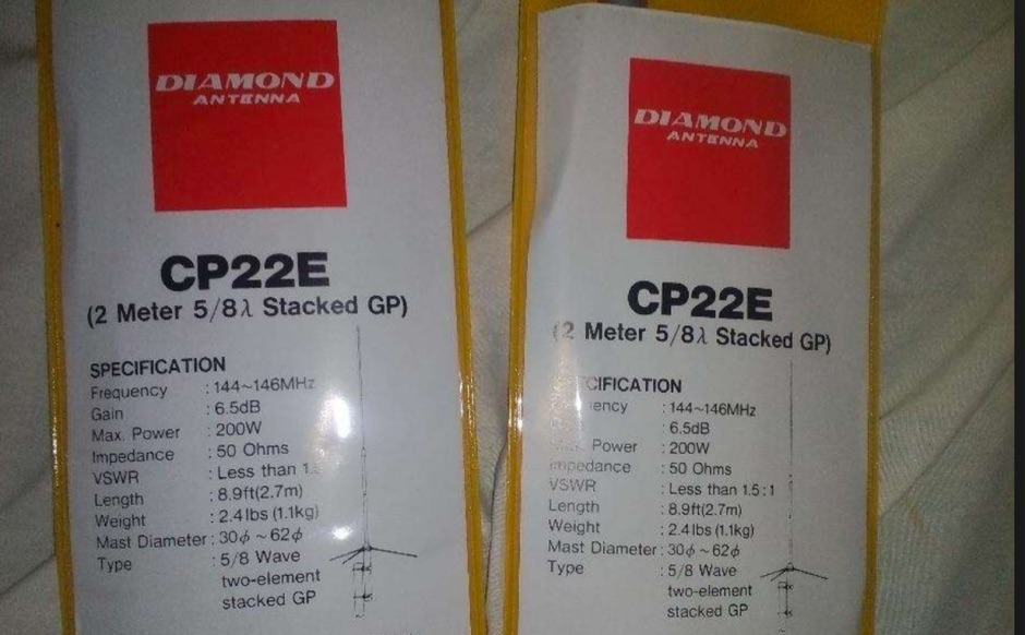 Diamond Antenna CP22E VHF base station antenna review. This antenna has a remarkable design achieving 5 dBi directivity in a slim low-profile design.
 -
 Selecting appropriate coaxial cable and wire for demanding amateur radio applications, particularly those involving high power or harsh environmental conditions, is crucial for maintaining signal integrity and operational safety. This resource details Harbour Industries' specialized offerings, which include Mil-Spec and commercial designs such as NEMA HP3/HP4 and SAE AS22759, suitable for aerospace, military, and industrial sectors. Their product line addresses the need for robust conductors capable of withstanding extreme temperatures and mechanical stress, often encountered in antenna systems or amplifier interconnections. The company highlights its AeroPOWER® Firezone M25038/3 cable, specifically engineered for high-temperature environments like aircraft engines. This particular product exemplifies their focus on solutions for critical infrastructure where reliability under adverse conditions is paramount. Such cables are relevant for hams building or maintaining stations in challenging climates or those operating high-power amplifiers where internal wiring must endure significant thermal loads. Harbour Industries also provides a range of high-performance cables designed to meet stringent specifications. Their expertise in high-temperature and high-performance cable manufacturing positions them as a supplier for specialized wiring needs beyond standard off-the-shelf options, ensuring durability and performance for advanced amateur radio setups.
 -
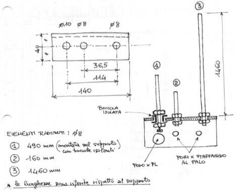 A multiband J-Pole antenna project that cover 144,220 and 430 MHz. The articles includes several pictures of this multi-band antenna, including handmade schematics and diagrams, project is mainly in Italian
 -
 Developing operational amateur radio equipment for the 134 GHz band presents significant technical challenges, particularly in frequency generation and stability. This resource details the construction of a 134 GHz system, outlining its architecture with separate transmit (Tx) and receive (Rx) modules, each employing a local oscillator (LO) and RF head units. The system utilizes a dual Flann 50 GHz lens-type horn antenna configuration for optimal signal coupling. The transmit path incorporates an LMX2541 synthesizer chip operating at approximately 2.8 GHz, referenced by a 10 MHz double-oven Morion OCXO for exceptional stability. This signal is multiplied through a series of stages (X4, then X2) to generate a 22.4 GHz signal, which subsequently drives a dual series diode multiplier to produce the final X6 signal for 134 GHz operation. The receive side features an anti-parallel diode mixer coupled to a 144 MHz transceiver via a preamplifier, ensuring effective downconversion. Operational mode is CW, achieved by keying a multiplier stage. The project includes images of the Tx and Rx head units and describes a successful 3.5 km test with G8ACE, demonstrating stable signal tones due to PLLs locked to OCXOs at both ends, confirming the system's robust performance.
 -
 A loop antenna for 80 and 40 meters band, the main loop is based by a crossed line using aluminium strip lines. The main loop diameter is 150 cm.
 -
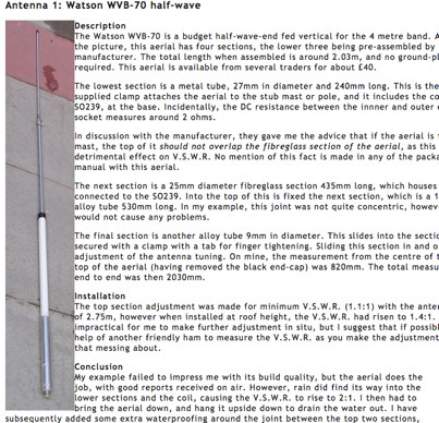 A comparison of commercial 4m verticals by by Ian Hogan G6TGO
 -
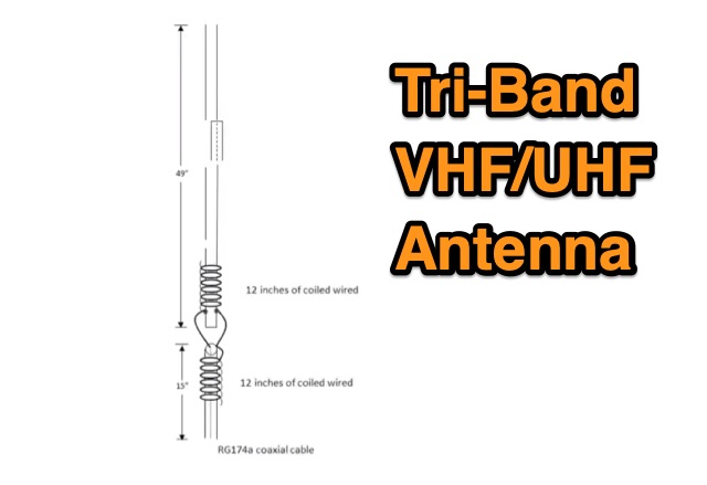 The TBJ-1 – a triband base antenna was published in March 2017 QST. This antenna covers 2M/220 MHz/70cm in one 6ft 3/4 inch PVC pipe and requires no radials.
 -
 Low-frequency (LF) radio time signals, operating primarily in the 40–80 kHz range, are broadcast by national physics laboratories for precise clock synchronization. Transmitters like **JJY** (40 kHz, 50 kW; 60 kHz, 50 kW), RTZ (50 kHz, 10 kW ERP), MSF (60 kHz, 15 kW ERP), WWVB (60 kHz, 50 kW ERP), RBU (66.66 kHz, 10 kW), and DCF77 (77.5 kHz, 50 kW) cover vast geographic areas, often several hundred to thousands of kilometers. LF signals offer distinct propagation advantages over higher-band transmissions such as GPS. Their long wavelengths (3–6 km) enable effective diffraction around obstacles like mountains and buildings. The ionosphere and ground act as a waveguide, eliminating the need for line-of-sight and allowing a single powerful station to cover extensive regions. Ground wave propagation minimizes ionospheric variability effects on transmission delay, and signals penetrate most building walls effectively. Robust and low-cost receivers, often priced at 20–30 USD/EUR, are widely used in radio clocks. These receivers typically comprise a tuned ferrite core antenna, a receiver IC (e.g., Atmel T4227, U4223B, MAS1016) for amplification and AM detection, and a microcontroller for decoding the time signal and phase-locking a local clock. Specific components for DCF77, MSF, and WWVB are readily available from vendors like HKW Elektronik and Ultralink.
 -
 Operating in a Single Operator Two Radios (SO2R) setup, especially with beverage antennas, often exposes the receiving radio's front-end to significant RF energy from the transmitting radio. This resource details a practical, homebrew receiver protection circuit designed to mitigate this risk. The core of the design involves a non-inductive 2W 22 Ohm carbon composition resistor in series with the RX antenna line, followed by two stacks of four fast-switching diodes (e.g., _1N914_) configured in opposite polarizations. This arrangement effectively clamps the incoming voltage to approximately 2.8 V peak-to-peak, safeguarding sensitive receiver input components. The series resistor plays a crucial role by absorbing excess power, preventing the diodes from exceeding their current ratings and potentially failing open, which would leave the receiver unprotected. The author, _N4KG_, measured up to 50 watts of coupled power between 80M slopers on the same tower, highlighting the necessity of such protection. The design is presented as a cost-effective solution to prevent damage to receiver input transformers, with the author noting successful protection of a receiver even after a resistor showed signs of overheating. This simple circuit can be integrated via a transverter plug, offering a robust defense against high RF input.
 -
 Documents S21RC's construction of an impedance transformer harness for a VHF/UHF cross yagi, utilizing 20m of _RG179_ cable. Details the creation of a DIY RF sampler with a -50dB sampling output, primarily for measuring HF radio PA section output with a Spectrum Analyzer, also applicable for _Pure Signal_ transmission. Chronicles the deployment of a 200m long beverage antenna for the _S21DX IOTA_ operation in 2022, positioned 2m above ground. Discusses the construction of a 3-element short beam for 10m to replace a previous 2-element antenna, with assistance from S21DW. Provides guidance on operating cheap _PA-70_ and _PA-100_ type Chinese SSPAs using IRF530 MOSFETs, emphasizing the necessity of a final LPF. Outlines the design and construction of a fully isolated interface for radio-to-computer connections, supporting various digital modes with isolated ground, audio transformers for IN/OUT, optical isolation for CAT/CIV, and isolated PTT/COS lines. Includes a log of software updates, such as the _HMI/TFT for NX8048K070_ and _2.1.14 Lite_ release with bug fixes for PEP hold and gradual watt decay.
 -
 In this post by N6CTA, discover the conversion of the Yaesu ATAS-120A screwdriver antenna for portable use. The author details the creation of two sets of radials, 16 and 32 in 16ft lengths, aiming to optimize the efficiency of ground-mounted antennas. Additionally, insights are shared on attaching male quick disconnect blade tabs, with potential plans for a radial plate kit.
 -
 How many times have you heard the advice to coil a few turns of coax at the antenna end to form a choke. How to find out if your common mode current choke really works
 -
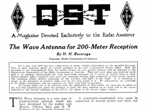 A QST Article published in November 1922 is about the origin of Beverage antennas, an unidirectional antenna type that was discovered and experimented for the first time in that period. This article is the introduction to beverage antenna theory, by the homonimous autho H. H. Beverage.
 -
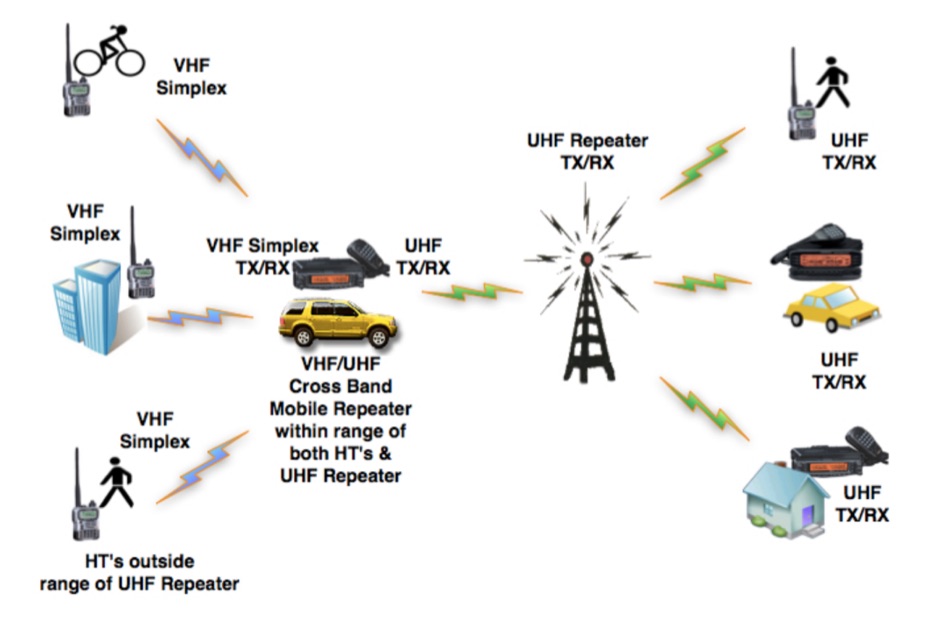 Crossband Repeating is a process where a Ham transmits one signal on one band (typically UHF), and it is received by another radio with a better antenna/power installation, and re-transmitted (typically on VHF) to another radio system, or a repeater. Everyday examples of cross-band repeaters are repeater receive sites that hear the input signals on 2m and retransmit those signals on a frequency higher than 220 MHz.
 -
 Experimental Long Boom Antennas - CP, LPDA, multiband with several NEC Files for 50MHz 144MHz 222 MHz 432MHz but also 902MHz and 1296 MHz Antenna projects. Includes also for each antenna model, in a general comparison table each antenna characteristics including Directive Gain, G/T, E-F/R, H-F/R abd Boom Length. This is a great value comparison table of several commercial and home made VHF UHF antenna projects.
 -
 Operating as FY/F5UII, Christian F5UII conducted a DXpedition to French Guiana (FY) from January 13 to 30, 2013. The primary operation utilized the FY5KE radio club station in Kourou, with activity focused on voice modes during specific weekday hours. The resource details the operator's intent to transmit before 12:00z and after 22:00z, or as availability permitted, from the mainland. A significant aspect of this operation involved a dedicated weekend activation of the Salut Islands, specifically **IOTA SA-020**, from January 19-20, 2013. This segment of the DXpedition was conducted from Royal Island (Ile Royale), part of a group including Devil's Island (Ile du Diable) and St. Joseph Island (Ile Saint Joseph), located 14 km offshore from Kourou. The station setup for the IOTA activation included 100 Watts of power, a GPA-030 vertical antenna for 10m, 15m, and 20m, and dipole antennas for 17m and 40m, with antenna deployment contingent on site conditions and propagation. The operator anticipated strong interest for the SA-020 entity.
 -
 Explains the fundamental purpose of a repeater, detailing how these automated relay stations overcome distance and terrain limitations for VHF/UHF communications. It traces the historical development from early Bell Telephone Labs "relay" stations in 1922 to Art Gentry, W6MEP's, pioneering K6MYK amateur radio repeater in the mid-1950s, which remains active today. The resource clarifies the distinction between simplex and duplex operation, including the unique function of a "parrot repeater" for single-frequency recording and playback. Delving into the internal workings, the guide breaks down a repeater into its core components: the antenna system, feedline (often _Heliax_ or hardline for minimal loss), duplexer, receiver, transmitter, and controller. It emphasizes the critical role of the duplexer in preventing receiver desensitization by isolating transmit and receive signals, even with distinct frequencies. The discussion highlights the importance of high-performance, durable antennas and low-loss feedlines, citing examples of equipment installed in the 1960s and 1970s that are still in perfect working order. Operating a repeater is also covered, with an explanation of frequency offset (e.g., the 600 kHz standard for 2 meters) and the function of _CTCSS_ (PL tone) for access. It outlines standard input/output offsets for various bands, from 6 meters to 23 centimeters, while noting regional variations. The guide also touches on features like autopatch and Digital Voice Recorders (DVRs), providing a solid foundation for understanding repeater technology and usage.
 -
 A dual band X-frame wire antenna made using 4 turns for response down to 3 MHz or so, and 2 turns (switched) for response up to around 18 MHz. The loop configurations are tuned using common eBay 365 pF tuning caps.
 -
 The 80-meter Skyloop antenna, a top-performing HF antenna, excels in weak signal work, low-noise operation, and omnidirectional coverage. Ideal for fixed stations, it delivers strong performance at low power, outperforming many alternatives, including 80m half-wave end-fed antennas. Requiring significant space for deployment, it’s well-suited for NVIS and groundwave use. Though not portable, it’s cost-effective and durable, with minor maintenance needs. Tuning may require adjustments for optimal resonance. It’s a standout for base stations, though a lighter portable version could enhance its versatility.
 -
 How to Design and Build a Field Expedient End-Fed Half-Wave Antenna for 20m, 40m and 80m. This Shorty 80m EFHW comprises a 49:1 autotransformer (to match the very high impedance at the end of a half-wave wire), a half-wavelength wire for 40m (also a quarter-wavelength for 80m), a loading coil and a short tail wire. The coil and the short tail wire (about 6 feet) make up the other quarter wave on 80m.
 -
 Magnetic loop receive antennas manufacturer. W6LVP loops cover 2200 through 10 meters (135 kHz through 30 MHz) with no tuning or adjustment.
 -
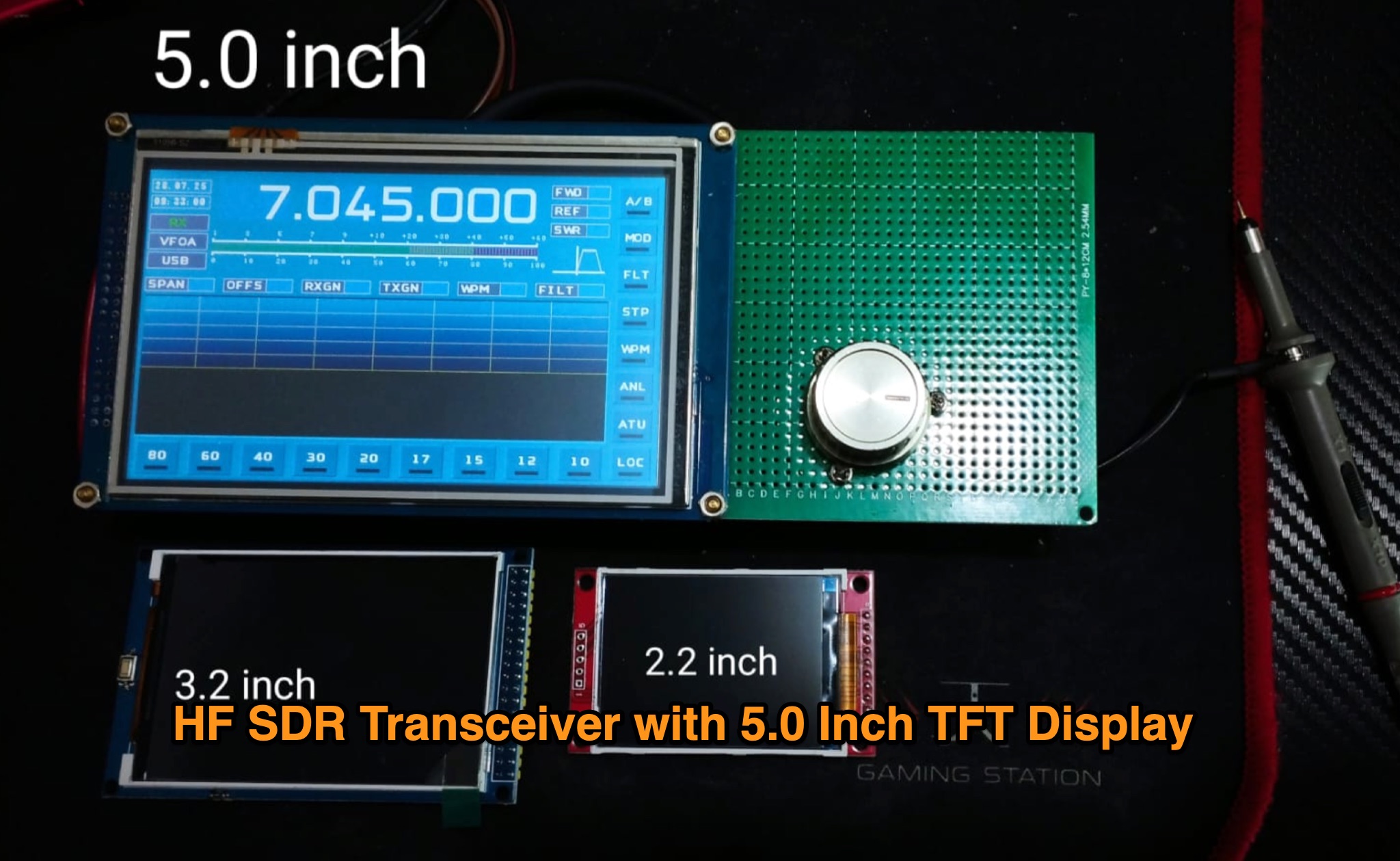 Author is currently developing the HS4HF 4 Band HF Radio Transceiver with a 5.0-inch TFT display, following their previous HSM1 model. They are also working on the Radio HSDRA, an All Band SDR HF Radio Transceiver with unique features such as DSP Digital Modulation, 100W final power, automatic antenna tuner, and more. The development includes a wide 5.0-inch display, touch screen, and various advanced functionalities. Stay updated with the latest developments in the world of HAM radio with Hambuilder Team.
 -
 Presents two distinct hardware modifications for the Icom IC-7300 transceiver, detailing the necessary steps for each. The first modification, a _MARS_ transmit expansion, involves the physical removal of specific surface-mount diodes (D422) from the main board, enabling transmit capabilities across a broader frequency range, including out-of-band frequencies. It specifies the diode location on US versions of the IC-7300 and suggests using small diagonal cutters if a soldering iron is not preferred or available. The second modification focuses on the internal antenna tuner, aiming to provide wider impedance matching capabilities. This involves adding a **100k ohm** resistor to a designated point within the tuner circuit. The resource also briefly mentions a microphone modification for the _HM219_ and a general power increase, though without specific instructions for the latter two. It emphasizes safety precautions, such as disconnecting power and inspecting the work area.
 -
 Over 1000 _Elecraft_ KX2 owners have benefited from the Kx22 Heatsink, experiencing cooler rig temperatures and higher output powers. PAE manufactures these heatsinks, along with AC power supplies for HF transceivers, remote power relays, and Ethernet relays, with all machined products manufactured in the **USA**. PAE distributes _Fair-Rite_ Mix 31 ferrite snap-it cores and toroid cores, essential for RFI suppression and impedance matching in amateur radio setups. The product line also includes commercial monitoring antennas, UQUI transformers, ULP AC power filters, and 3M conductive adhesive copper tape, catering to various station build-out and maintenance needs. The AM1 Portable Antenna Mount System and its AM1-VA Multi-Angle Adapter offer flexible antenna deployment options. PAE ensures careful packing of fragile ferrite products, with shipping cost adjustments communicated post-order for larger, heavier combinations to guarantee safe delivery.
 -
 This guide explores the captivating hobby of shortwave listening (SWL), offering insights for beginners and enthusiasts alike. It covers key shortwave broadcast bands, essential tools like antennas and receivers, and practical tips to enhance listening experiences. Recommendations include budget-friendly SDR receivers, traditional radios like the TECSUN PL-680, and antennas suited for various environments. Additional resources, such as the World Radio & TV Handbook and online tools like Short-Wave.Info, are highlighted to help identify signals and maximize the enjoyment of SWL.
 -
 Presents a detailed construction guide for a 9 dB, 70cm collinear antenna, utilizing readily available _RG58/U_ coaxial cable and PVC pipe for housing. The resource outlines the critical calculations for ½ wavelength sections at 444 MHz, incorporating the coaxial cable's velocity factor of 0.66, which yields a section length of 223 millimeters. It specifies the preparation and soldering of eight such half-wavelength sections, each cut to 231mm to allow for trimming, forming the core of the array. Further instructions detail the integration of a ¼ wave element (169mm #16 solid wire) at the top and a ¼ wave aluminum tube (160mm, 5/16 inch) at the bottom, crimped to the feed point's braid. The guide also addresses RF common mode current suppression by suggesting the use of _FT50-43_ toroids on the feedline. Final assembly steps cover mounting the antenna within ¾" PVC pipe using a wooden dowel, waterproofing connections, and initial SWR checks. The article also discusses scaling the design for different element counts and other VHF/UHF bands.
 -
 A 5/8 λ antenna, often thought to be ideal for all frequencies, has unique characteristics that don't universally apply. First introduced for medium-wave radio, it works optimally at 225° antenna length over ideal ground, yielding high efficiency. However, at VHF and higher frequencies, it offers no advantage over other antennas due to real ground conditions and complex matching requirements. DIY calculators provide only rough estimates, useful as a starting point for simulations, not for precise builds.
 -
 A half wave wire that is tuned for resonance on 80m will NOT be resonant on 40m despite a precise harmonic relationship between the two bands. The End Effect is caused by a capacitive coupling between an unterminated wire end and the ground.
 -
 PH0NO conducted field tests comparing a mobile antenna (DX-UHV) to an end-fed half-wave wire. Results on 20m showed the end-fed wire outperforming the mobile antenna, with a significant difference in signal strength. On 40m, the end-fed wire surpassed the mobile antenna in spots and reach. While the mobile antenna is more practical, the end-fed wire offers superior performance. Further testing is planned.
 -
 This is a theoretical look at propagation on 630-Meters and 2200-Meters using ray tracing software. It expands on the brief discussion in the ARRL Handbooks. The Earth's magnetic field affects 630-Meter and 2200-Meter band propagation. Lower ionization reduces absorption, aiding low-frequency propagation. Differences exist between bands, limited daytime sky-wave propagation. Sunrise/sunset show promise, yet mechanisms are unclear. Ducting possible at night in specific conditions. Negative ions enhance propagation. Inefficient antennas and high man-made noise are anticipated. Groundwave propagation is significant on 2200-Meters.
 -
 A guide to constructing a simple quarter-wave ground plane antenna, detailing design principles and providing dimensions for VHF/UHF bands
 -
 The TY0RU DXpedition to Benin in 2022 achieved over **100,000 QSOs** from Cotonou, IOTA AF-051, operating across 160m through 6m bands using CW, SSB, and FT8 modes. The operation involved a team of 12 operators, including _F5RAV_, _F4WBN_, and _F1TCV_, utilizing multiple stations with transceivers like the Icom IC-7300 and IC-7610, paired with amplifiers and various antennas such as verticals, dipoles, and a 4-square array for 40m. The expedition's log is available on Club Log, supporting OQRS for both direct and bureau QSLs, with F5RAV serving as the QSL manager. The site details the team's travel, setup, and operational challenges, including local conditions and equipment deployment, offering insights into the logistical complexities of activating a rare DXCC entity. Donors are acknowledged, and a photo gallery documents the activity.
 -
 Demonstrates the construction of an active loop converter specifically designed for the Low Frequency (LF) bands, addressing common localized noise interference in LF reception. The design integrates a sharply tuned circuit and a tuned loop antenna, utilizing the loop as the sole tuned inductive element. By applying positive feedback, the converter significantly increases the loop's effective Q, achieving factors between 1000 and 2000, which sharpens tuning and reduces noise. The circuit employs an _NE602_ mixer stage, feeding its output to an HF receiver, with a crystal-locked local oscillator at 4 MHz. A 20-turn, 0.8-meter square loop antenna with 500 uH inductance is detailed, connected via 2 meters of figure 8 flex cable. The converter offers three selectable frequency bands: 195-490 kHz, 150-220 kHz (including the New Zealand amateur band), and 128-160 kHz (covering the European amateur band). Performance measurements indicate an effective 3dB bandwidth of approximately 100 to 200 hertz at 200 kHz. The article provides insights into component selection, including an _LF353_ op-amp and a trifilar wound transformer on a ferrite core. Sensitivity figures are presented, showing 7.5 uV of converted output per 1 uV/meter signal strength into a 50-ohm load, or 37.5 uV into an _FRG7_ receiver, highlighting its capability to extract weak signals from noise.
 -
 Operating an **Echolink** gateway on the 4-meter band presents unique opportunities for extending VHF communications, as demonstrated by the EI4FMG node. Situated at Fieldstown, Monasterboice, this gateway provides coverage across a significant portion of Ireland's east coast, leveraging a Tait TM8100 radio and an EI4JR Echolink interface logic. My own experience with similar setups confirms the importance of strategic site selection for maximizing reach, particularly with a 122-meter elevation above sea level. Access to the EI4FMG gateway, identified by node 57006, requires a **CTCSS** tone of 88.5 Hz, a standard practice for managing access and minimizing interference on shared frequencies. The system transmits with 15 watts of power and utilizes a Sigma CAT70 @5MAGL antenna, a configuration well-suited for regional VHF coverage. The gateway also features an auto-ID every 8 minutes, ensuring compliance and clear station identification. Users can interact with the gateway using various DTMF commands, allowing for connections to specific nodes, random repeater/link or conference nodes, and managing disconnections. These functionalities streamline the process of linking into the broader Echolink network, enabling local VHF operators to communicate globally through the internet backbone.