Search results
Query: show
Links: 325 | Categories: 2
-
 ON4VT SSTV and personal page, includes a large software review, introduction for beginners and webcams showing sstv on the net
 -
 If you have a computer with word processing software and a printer, you can make your own custom QSL cards, with each card individually printed for the ham you just contacted. WA7S show you how.
 -
 Constructing a compact, two-band magnetic loop antenna for HF operation, especially from constrained locations like a balcony, presents unique challenges. OK1FOU's design, inspired by DJ3RW's 50 MHz loop, addresses these by employing an unusual side-fed configuration and placing the symmetric, two-section variable tuning capacitor at the bottom of the loop, directly connected to the coax shield. The article provides specific material recommendations, including two 1-meter wooden pales and about 3 meters of thick loudspeaker cable, noting the high current (60A at 100W) in the loop. Construction steps detail forming two turns with a 5 cm gap, using a GDO to pre-tune the open loop to a frequency slightly above the desired highest band, and then integrating the tuning and coupling capacitors. For 10/14 MHz, an open loop resonance of 16-17 MHz is suggested. Practical experience with the 10 MHz band from a third-floor balcony in Prague (JO70GC) shows a 1:1 SWR across most of the band without an external ATU. While DX traffic was modest due to the urban environment, QSO examples with RA6WF, LA6GIA, G0NXA, and LZ1QK on 10 MHz are provided, demonstrating its operational capability.
 -
 Displays map of the world, showing day and night areas.
 -
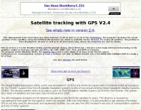 The program calculates the actual position of the satellites using the NORAD 2LINE-element set, which is available via the Internet, for nearly all satellites. The position is then displayed in 3D-view as well as in 2D (mercator) view, where the footprints are also be shown.
 -
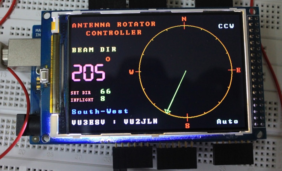 This is an attempt to build an Antenna rotator controller using Arduino Mega 2560 with a nice user interface showing the actual position of the antenna.
 -
 Midland GXT-900 FRS/GMRS 30-Mile Range Two-Way Radio product review
 -
 How Ham Radio Works, by Gary Brown, Ham radio can be very portable and affordable. In this article, we will look at ham radio and show you how to get started in this wireless world
 -
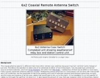 6x2 coaxial remote antenna switch, completed unit showing weatherproof relay box and station control unit.
 -
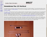 This page shows a homebrew vertical antenna based on the Pac-12 antenna design.
 -
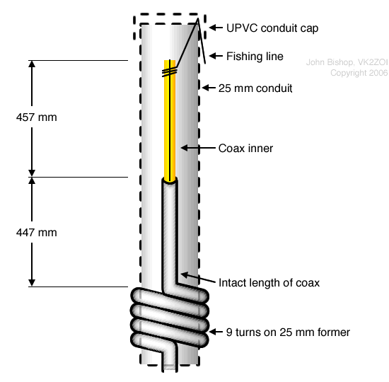 The diagram below shows the basic arrangement of the 2m Half-Wave version of the antenna. A 6m diagram is available too.
 -
 Measurements that show it doesn't make much difference
 -
 This is a popular antenna design as the performance is very good across the HF bands and requires little or no tuning. It is a dipole fed off center with a 4:1 current balun at the offset feedpoint. The antenna shown covers 80, 40, 20 and 10 meters with 15 meters and WARC bands
 -
 The Grid Yagi (or Grid Quad) is a high performance yagi antenna that can be built with readily obtainable inexpensive materials. Described here is a 6 element 2 meter version with a boom length of about 1 wavelength, shown
 -
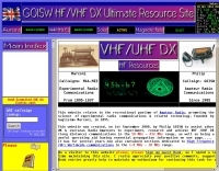 VHF/UHF DX site showing latest propagation, software, radio dealers, awards, maps etc.
 -
 MorseMaker is an up-to-date replacement for the Morse Machine shown further down this page. It has been re-written using a different programming language and is now entirely 'stand-alone' requiring no run-time support files. This version also works with Windows XP and can use the soundcard but please note that, unlike its predecessor, it does not split the alphabet into smaller 'learning' blocks and does not incorporate the Morse reader.
 -
 Live realtime satellite tracking system show current status of amateur radio satellites, ISS tracking is also provided by showing ISS Visible Passes based on your own location. This web site show the International space station live position and can be used as an iss tracker app to determine future satellite and ISS transit over your location.
 -
 The purpose of this page is to show you how you can access a DX Cluster via the Internet. There are many software applications available, some are free some are not. Excellent page from OZ2M
 -
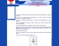 The Crossed Field Antenna (CFA) is one of the applications of Correction of Maxwell's Equations which was used over 150 years ago which was proved these days that the Magnetic Field Source is only the Displacement Current not the Conduction Current . These Corrections was made by an Egyptian Doctor Engineer Fathi Kabbary , who reached the New Correct Theory which shows that the height and efficiency of the antenna doesn't depend on the wavelength
 -
 This page shows W5AJ & KD5AAU setting up a self supporting crank over tower.
 -
 The IndyScan website functions as a personal blog, documenting the author's experiences across various aspects of daily life, including travel, culinary adventures, and media consumption. Content frequently details personal trips, dining experiences in Indiana and other locations, and reviews of books, television shows, and products. The site also includes reflections on local events and personal purchases, providing a snapshot of the author's interests and activities. While the site's primary focus is personal narrative, it occasionally touches upon amateur radio, such as mentions of operating during a trip to Brookville, Indiana, or capturing a weather fax via shortwave radio. These ham radio-related entries are integrated within broader lifestyle updates, offering a glimpse into the author's engagement with the hobby rather than providing technical guides or detailed operational information. The resource serves as a personal journal, not a dedicated technical reference for amateur radio.
 -
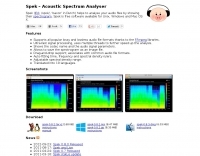 Spek helps to analyse your audio files by showing their spectrogram. Spek supports all popular lossy and lossless audio file formats. Spek is free software available for Unix, Windows and Mac OS X.
 -
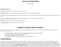 Receiving Common Mode Noise shows how lack of a balun can contribute to system noise
 -
 Demonstrates the product line of _LZ Antenna Ltd._, a Bulgarian manufacturer specializing in amateur radio antennas and custom electronic devices. The company focuses on robust, high-quality HF multiband Yagi and vertical antennas, leveraging over 20 years of experience from founder Georgi Georgiev in radio amateur development. Featured models include the LZA 8-4, LZA-10-3, and the LZA-7-3A WRTC 2022, alongside various rotary dipoles like the LZA1 40/30m. Provides specifications for several Yagi antennas, such as the LZA-9-5, LZA-13-7, and LZA-6-3 (a 6-element, 3-band design). The company emphasizes applying "leading edge technology" to high-frequency communication equipment production, with products designed for durability and performance. The LZA-10-5 Yagi offers **12.5 dBi** gain on 10m, while the LZA-13-7 provides **13.2 dBi** on 20m, showcasing competitive gain figures for DXing and contesting.
 -
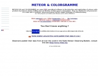 METEOR v 4.0 DOS and COLORGRAMME Specialized software in the detection and registration of echoes radio products by meteors shower (falling star) at the time of their gone in atmospheric
 -
 Various publications through the years have shown how the SWR measured on a shorted (or open) feed line can be used to calculate feed line attenuation
 -
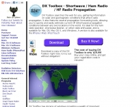
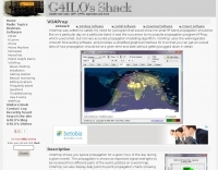 VOAProp shows you typical propagation for a given hour of the day during a given month. The propagation is shown as expected signal strengths to be received from different parts of the world, plotted on a world map. Windows freeware by G4ILO
 -
 Based on original G2BCX design this J-Pole antenna for the six meter band is made with a homemade ribbon cable. The antenna shown in this article includes a coaxial cable choke feed to remove RF currents from flowing on the outer of the cable.
 -

-
 This free program displays the location of any locator on a map. It calaculates between two Maidenhead locators the distance (km and miles) azimuth longitude latitude Show the location, direction and distance as you move your mouse on a map! Graphical Locator Program, By ON6MU
 -
 A 500-watt mobile antenna project details the conversion of an old 10m hamstick into a highly efficient, multiband "bugstick" for HF operation. The core modification involves replacing the original coil with 25 turns of 6 turns-per-inch, 1.5-inch diameter coil stock, fabricated from #14 wire. This design, intended for a 3-magnet mount on a vehicle cab, achieves resonance on multiple bands by shorting out specific turns on the coil, similar to a **bugcatcher** antenna. Measurements taken with an MFJ-259 analyzer on a GMC pickup show 0 turns shorted for 20 meters (14.2 MHz), 10 turns for 17 meters, 16 turns for 15 meters, 19 turns for 12 meters, and 23 turns for 10 meters. The construction emphasizes using UV-resistant tie-wraps and #14 solid wire with crimp lugs for robust RF connections, bypassing the fiberglass rod for current flow. A bonus section details a 40-meter version, utilizing 48 turns of 8 TPI, 2-inch diameter coil stock.
 -
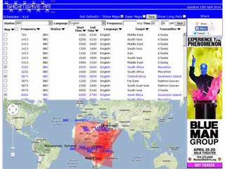 Shortwave Radio Schedules from Eibi/AOKI combined lists. Includes Google maps showing beam directions and long paths.
 -
 50 MHz meteor scatter offers a unique opportunity for amateur radio operators to make long-distance QSOs, even when the band appears dead. Meteor scatter involves reflecting radio waves off the ionized trails left by meteors burning up in the upper atmosphere, typically around 105 km high. These trails can facilitate contacts over distances up to approximately 2,300 km. The technique is particularly effective during meteor showers, which increase the number of meteors and thus the chances of successful QSOs. However, random meteors can also be used to achieve contacts, especially on the 50 MHz band, where the longer reflection time compared to 144 MHz makes it easier to work meteor scatter. Operators should be prepared to make QSOs in short bursts, often lasting only a few seconds. The IARU Region 1 meteor scatter procedure recommends using 2.5-minute periods for telegraphy and 1-minute periods for SSB, though shorter periods can be arranged. For 50 MHz SSB, 15-second timing is often used to maximize the chances of completing a contact. The procedure involves specific timing for transmissions based on direction and requires both operators to confirm receipt of callsigns and reports to complete a QSO. Understanding the geometry of meteor scatter, including the optimal radiation angles and the concept of 'hot spots,' is crucial. These hot spots are areas where reflections are most likely to occur, influenced by the Earth's rotation and the path of the meteors. Proper antenna setup, including elevation control and beam direction, can significantly enhance the chances of successful meteor scatter QSOs.
 -
 Details Guglielmo Marconi's foundational contributions to radio communication, highlighting his 1898 Patent **7777** which introduced tuning circuits for independent simultaneous communications. Chronicles the historic transatlantic reception of the Morse code letter 'S' on December 12, 1901, from Poldhu, Cornwall, to St. John's, Newfoundland, a distance of over _3,500 kilometers_. The exhibit showcases early Marconi 10-inch spark transmitters, identical to those used on the _Titanic_, alongside Canadian Marconi crystal detector models. It also features high-end commercial receivers like the IP501, weighing **87 pounds** and originally priced at $595.00, demonstrating the robust construction and technological advancements of the era.
 -
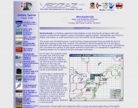 WorkedGrids is a Windows application that displays a map showing the amateur radio grid squares contacted and logged in using a third-party logging program. WorkedGrids uses colors to display information on a per-band basis. Up to four bands can be displayed concurrently by VE2ZAZ Bert
 -
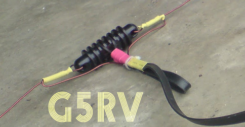 Homebrew G5RV a simple multiband antenna. This article shows detailed pictures of a G5RV home made antenna, including antenna size and dimensions by 9M2ZAK
 -
 FREE specialized software in the detection and registration of echoes radio products by meteors shower, falling star, at the time of their gone in atmospheric. They are destined to all possessors of a radio and a computer, interested parties by this simple technique of radioastronomy.
 -
 A 50-ohm 10W resistor forms the core of this portable QRP antenna, designed by _K0EMT_ for convenient operation on 160m and 80m. The construction involves soldering the resistor to a BNC connector, with one lead to ground and the other to the center conductor, then insulating the assembly. This minimalist design aims to provide a highly portable solution for low-band QRP operations, acknowledging the inherent trade-offs between antenna size and efficiency. Testing with an antenna analyzer revealed low SWR on both 160m and 80m, with a Yaesu FT-817 confirming good matching. While 40m and 30m showed higher SWR, the primary focus remains on the lower bands. The author successfully tested the antenna with **2.5W CW** output, demonstrating its practical application for QRP field operations where ease of deployment is paramount, even if it means sacrificing some **gain** compared to full-sized antennas.
 -
 Beaconmap is a Win95/98/NT program to help listeners to identify the beacon stations of the NCDXF/IARU beacon network. The program displays a flashing dot at the location of the beacon that is currently transmitting. The call sign of the beacon, as well as the QTH is shown in the status bar. By PA1ARE
 -
 This program extracts statistics from a dx.dat file to show numbers of spots for each country on each band
 -
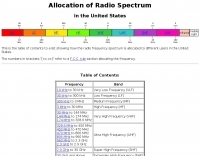 This is the table of contents to a list showing how the radio frequency spectrum is allocated to different users in the United States.
 -
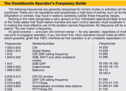 The Considerate Operator's Guide shows frequencies generally recognized for certain modes or activities (all frequencies are in MHz).
 -
 Accurately determining an antenna's feedpoint impedance is crucial for optimal performance, especially when experimenting with new designs or making adjustments. While SWR meters provide basic information, a full complex impedance measurement reveals the resistive and reactive components, which are essential for proper matching. Modern antenna analyzers, like the _Palstar ZM30_ or MFJ259B, simplify this task, but measurements taken through a transmission line require careful interpretation due to impedance transformation. This resource details a calibration method to precisely account for the effects of the feedline. It explains how a transmission line can significantly alter the measured impedance, illustrating this phenomenon with a Smith Chart example where an 80m antenna's [22 + j6] Ohms feedpoint impedance transforms to [82 + j45] Ohms after a 10m line. The guide demonstrates using a transmission line calculator applet, such as the one by W9CF, to reverse this transformation. It outlines the process of calibrating a specific length of RG174 coax, showing how an initial 26ft estimate was refined to **25.85ft** to accurately predict a known 22 Ohm load, significantly improving accuracy over uncalibrated results.
 -
 Iphone app for ncdxf IARU beacon monitoring, shows the currently transmitting beacon on each band, reception charts from the active monitoring stations, and latest solar flux A and K indices
 -
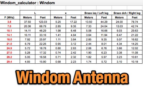 This article describes the characteristics of the Windom antenna and shows the results of several simulations made with MMANA-GAL, covering models optimized for the 20 m, 40 m and 80 m bands.
 -
 A radio's transmitting power can be concentrated along the horizon by use of a GAIN antenna. Although you may still be transmitting with four watts of power, your effective radiated powerwill be greatly increased. This table shows the effects of antenna gain on a transmitter with 4 watts of transmit power.
 -
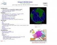
 This program allows both great-circle (polar) and rectangular projections of the world. The great-circle map is centered on any specified latitude and longitude (the "home" location). The rectangular projection is shown with the home longitude in the middle of the screen.
 -
 Windows program for analyzing vertical antennas. This program shows the resistance and reactance to be expected looking into a cylindrical metallic tower over a perfect ground. It gives a useful approximation of the values to be expected in a real-world situation.
 -
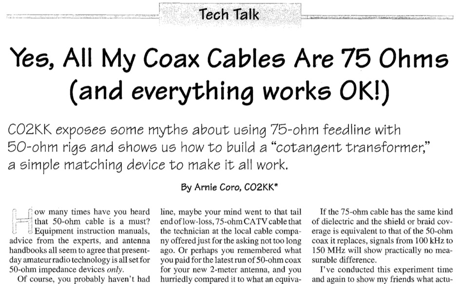 CO2KK exposes some myths about using 75-ohm feedline with 50-ohm rigs and show how to build a cotanget transformer
 -
 Demonstrates the construction of a 144 MHz turnstile antenna, detailing its design for omnidirectional, horizontally polarized VHF operation. The resource outlines the physical dimensions and materials required, including specific lengths for the radiating elements and the use of _RG-58_ coaxial cable for phasing. It covers the assembly process, emphasizing the critical spacing and connection points to achieve the desired radiation pattern and impedance matching for the _2-meter band_. The article presents measured _SWR_ performance across the 144-146 MHz segment, showing a low SWR of 1.2:1 at 144.5 MHz, which is suitable for general VHF use. It compares the turnstile's performance to a 9-element Yagi, noting the turnstile's advantage in providing consistent signal strength from all directions without requiring a rotator. Practical application for local FM simplex and repeater operations is implied, offering a simple yet effective antenna solution for fixed or portable stations.