Search results
Query: used 6 meter
Links: 86 | Categories: 2
-
 Sort of similar to the one of the 6m omni. Instead of using twin-lead, this design makes use of a more or less regular double bazooka antenna (coaxial dipole). Your attention shall be drawn to the available standart literature, such as Rothammel. In order to "compute" the dimension, Karl Rothammel mentioned that the total length of the dipole shall be 95% of the free-space wavelength. The short-circuit bridges (closing the folded dipole) are to be placed at a distance-fraction being equal to the velocity factor of the coax cable used, which will be 66% using RG-58 or RG174.
 -
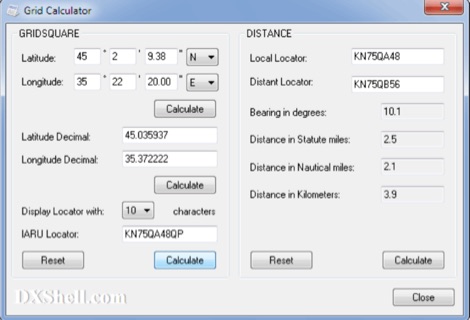 Grid Calculator allows you to calculate either a grid square locator or the latitude and longitude of a location. Grid Calculator can be used to calculate a Great Circle bearing and distance between two stations in statute miles, nautical miles, and kilometers.
 -
 A simple portable dipole antenna for the 40 meter band using a total lenght of 18 meter. It can be used for 80 to 10 meters coverage using a antenna tuner.
 -
 A 0-30 MHz step attenuator, constructed from switchable Pi attenuation pads, provides a practical tool for evaluating receiver sensitivity and calibrating S-meters. The design utilizes readily available 5% tolerance resistors, with values derived from paralleled components to achieve specific attenuation steps. A schematic (Fig 1) illustrates the circuit, including PCB pad shielding, while a table details required and actual resistor values, along with percentage differences. Measurements of voltage input versus output at various frequencies are used to calculate dB attenuation, presented in a graph (Fig 4). The resource includes formulas for determining output voltage from a known input and a comprehensive 0-40 dB voltage multiplier table, which is crucial for precise signal level management. The project also references external attenuator calculators and equations for further study. Photos (1-3) provide visual guidance for the assembled unit, showing bottom, top, and front views. The project emphasizes the use of **Pi attenuation pads** and **receiver sensitivity** evaluation, offering a hands-on approach to RF signal management.
 -
 The W6JWS 2-meter Repeater Maintenance and Repair Log documents the ongoing upkeep of a 146.745 MHz repeater, specifically addressing modifications to enhance its functionality. It details changes made to ensure the repeater powers up in _PL mode_ and to improve the reliability of touch-tone control, drawing comparisons to similar work performed on the AE6KE repeater. The log also notes a repair to a fused wire in the reverse battery protection circuit after an accidental polarity reversal, highlighting a temporary workaround where a wire was omitted but the system remained operational. The resource includes practical insights from Jeff Liebermann, AE6KS, regarding jumper configurations and programming, with accompanying photos. It provides access to several documents for the Icom RP-1510 repeater, including operating manuals and a schematic for the single logic board version, which differs from the dual-board configuration described in some printed manuals. The log mentions a specific modification to adjust the dropout delay, which was later deemed unnecessary, and references a related project for the AE6KE repeater, aiming to replicate successful modifications on the W6JWS machine, resulting in improved touch-tone reliability and proper PL mode activation.
 -
 Low-frequency (LF) radio time signals, operating primarily in the 40–80 kHz range, are broadcast by national physics laboratories for precise clock synchronization. Transmitters like **JJY** (40 kHz, 50 kW; 60 kHz, 50 kW), RTZ (50 kHz, 10 kW ERP), MSF (60 kHz, 15 kW ERP), WWVB (60 kHz, 50 kW ERP), RBU (66.66 kHz, 10 kW), and DCF77 (77.5 kHz, 50 kW) cover vast geographic areas, often several hundred to thousands of kilometers. LF signals offer distinct propagation advantages over higher-band transmissions such as GPS. Their long wavelengths (3–6 km) enable effective diffraction around obstacles like mountains and buildings. The ionosphere and ground act as a waveguide, eliminating the need for line-of-sight and allowing a single powerful station to cover extensive regions. Ground wave propagation minimizes ionospheric variability effects on transmission delay, and signals penetrate most building walls effectively. Robust and low-cost receivers, often priced at 20–30 USD/EUR, are widely used in radio clocks. These receivers typically comprise a tuned ferrite core antenna, a receiver IC (e.g., Atmel T4227, U4223B, MAS1016) for amplification and AM detection, and a microcontroller for decoding the time signal and phase-locking a local clock. Specific components for DCF77, MSF, and WWVB are readily available from vendors like HKW Elektronik and Ultralink.
 -
 A rotary dipole antenna for 30 meters band. Each arm is about 12.5 ft and is constructed from telescoping fibreglass flag/fishing poles and short lengths of aluminium tubing. Two short lengths of glass-fibre rod were used to insulate the arms from the supporting hardware.
 -
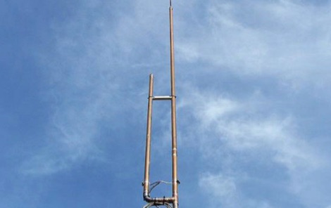 A homemade j-pole antenna for six meters band, designed to work on local repeaters, and working on the 52-53 MHz. Includes a list of needed materials and detailed description on assembling the copper tubes used to build this antenna.
 -
 Basically, this antenna is a 23-foot wire fed through a 4:1 un-un transformer. This antenna can be easily used in portable operation, for operating all bands from 40-10 meters.
 -
 The simple balcony vertical HF antenna made with plastic fishing pole. Just along the pole I install copper wire in 7 meter length. Then was installed ATU. It was used home brew tuner. For each band was used one counterpoise in length 0.8 x lambda/4
 -
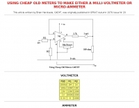 This article include a circuit that allows a cheap 0-1mA meter to be used as a micro-ammeter or a milli-voltmeter
 -
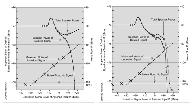 An explanation of the different procedures and definitions that are commonly used for blocking dynamic range (BDR) measurements. Dynamic range in general is the ratio between the weakest signal a system can handle and the strongest signal the same system can handle simultaneously without an operator switching attenuators or turning volume potentiometers
 -
 This type of antenna is a popular antenna design as the performance is very good across the HF bands and requires little or no tuning. It’s a dipole fed off center with a 4:1 balun at the offset feed point. The antenna shown covers 80, 40, 20 and 10 meters. The formula can also be used to adjust the overall length to cover more or fewer bands and the resulting overall length. 160-10m, 80-10m or 40-10 meters depending on your available space. Other bands will require a tuner.
 -
 This device was designed as an SWR and power meter for Radio Amateurs. In addition to SWR, it measures forward and backwards power, therefore can also be used as a wattmeter. With a large measuring range from 1 to 1000 watts, it is suitable for use from QRP to QRO
 -
 Operating in antenna-restricted communities presents unique challenges for amateur radio operators, often necessitating creative solutions for antenna deployment. This resource details the design and implementation of stealth antennas within a townhouse community in Exton, PA, where external antennas were strictly forbidden by covenants. The author, WB5NHL, describes his setup, which involved locating the shack in the basement and utilizing an unused space under the roofline of a finished third-floor loft for antenna placement. The content specifically addresses the practicalities of routing coax cables three floors and maximizing antenna performance within limited attic space. It covers solutions for multi-band operation, including dedicated sections for 40-10 meter and 80-meter antennas, along with strategies for mitigating potential interference issues. The approach emphasizes full compliance with community covenants, achieving maximum height-above-ground for horizontal antennas, enabling instant band switching, and efficiently utilizing available attic volume. While acknowledging limitations such as potential interference with high power and fixed antenna patterns, the resource provides a detailed account of a functional compromise for restricted environments. Links to individual pages on _coax cables_, _40-10 meter antennas_, _80-meter antennas_, and _interference issues_ offer deeper dives into each specific aspect of the installation.
 -
 Vertical end fed antenna used for portable operations. The antenna will work on 80 with acceptable results, it will work fine on 40m, and it will be a good deal better than a normal 1/4 wave GP on 20, 17, 15 meters.
 -
 A mircovert antenna assembled for the 40m version of the DL7PE antenna. A one meter long aluminum tube with 24mm diameter is used for the base (element 1) and a 50cm aluminum tube with 20mm diameter for element 2 (the extention). A pvc pipe, 34cm long and with a diameter of 38mm, is used to wind the coil on (1mm enamelled copper wire).
 -
 2 Wavelength ,2 Meter Bi-Square Beam , 5dbd gain. This antennas are very cheeap to build and their radiation pattern is similar to a figure 8 with maximum signal through the loop but they may be used as a near-omnidirectional antenna
 -
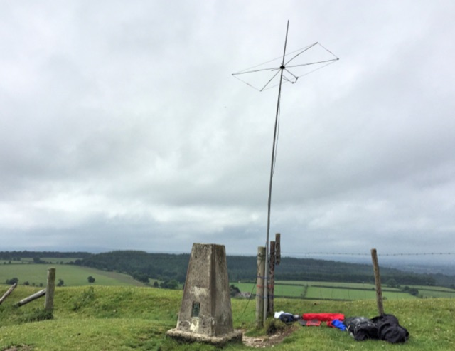 Bring the six meters with you during your hoilidays. This article features a portable moxon antenna for 50 MHz used for sota portable operatios
 -
 This air-core solenoid style RF inductor calculator calculates the inductance, wire size, number of turns, and other parameters for an air-core solenoid inductor used in radio frequency (RF) circuits, based on user input of frequency, desired inductance value, and physical dimensions.
 -
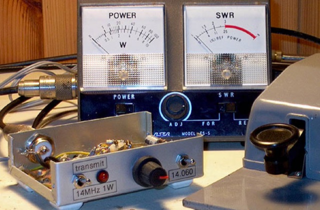 The 1 watt 20 meter QRP transmitter with VXO. This is a nice QRP transmitter that can be used in combination of one of the simple receivers.
 -
 This document provides a detailed guide on constructing and mounting a folded dipol for the 146 MHz frequency in a vertical configuration to be used in Yagi antennas. The step-by-step instructions and diagrams included make it easy for hams to build and set up this type of antenna. Understanding and implementing this design can enhance the performance of radio communication for Amateurs operating in the 2-meter band. Whether you are looking to improve your signal strength or experiment with antenna designs, this resource offers valuable insights and practical information.
 -
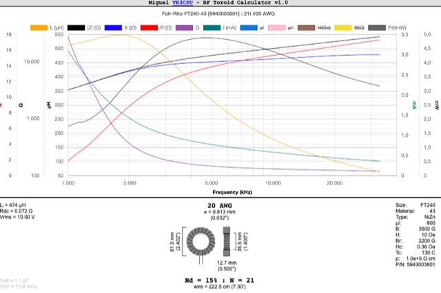 This RF Toroid Calculator provides graphical calculator used to determine the inductance and other parameters of ferrite and powdered-iron toroids. It simplifies the process of selecting the appropriate toroid for use in radio frequency (RF) circuits
 -
 This article describes the phases for the construction of a Yagi antenna. The calculations of the parameters are made using 4NEC2 software. This type of antenna is used for transmissions and receptions of electromagnetic waves. The project shown here refers to the frequency of 433.92 MHz.
 -
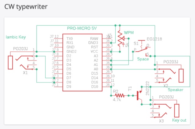 The CW typewriter is a compact adapter board that transforms Morse code into ASCII characters using an Iambic key. It connects to a computer via USB, emulating the keyboard. The device features inputs for Iambic keying and a WPM speed potentiometer, and outputs for a key and a speaker for side tone. The device can be used with various software and online typing games for practice, offering a unique and interactive way to learn and use Morse code.
 -
 This is a design based on the QuickYagi 4 software by WA7RAI with some changes for practical reasons. The beam uses 6.5 metres of standard 25mm square boom, 12mm diameter elements without tapers. The actual boom length used is 6.3 metres and all parts are readily available.
 -
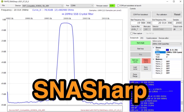 SNASharp is a free software application designed to work with scalar network analyzers compatible with NWT software from DL4JAL. It is used to measure and analyze the scattering parameters (S-parameters) of microwave devices. Provide several measurements and analysis tools including Smith chart, Polar plot, S-parameter tables, Transmission line calculator
 -
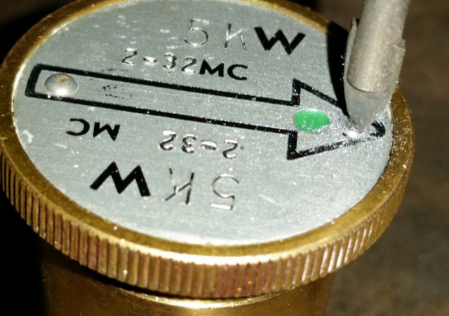 How to repair and calibrate a used Bird model 43 wattmeter.
 -
 The DIY Power Meter project utilizes the _INA226_ high-side power monitoring chip, paired with an ATtiny85 microcontroller, to measure voltage, current, and power, displaying the results on a 128x32 OLED screen. The INA226 communicates via an I2C interface and is programmed with a calibration factor based on the shunt resistance and current register LSB. The project is designed to handle a maximum current of 500mA using a 0.16ohm shunt resistor, which can be adjusted to a 0.2ohm resistor, reducing the full-scale current range to 409mA with a resolution of **12.5uA**. The shunt resistor dissipates only 33mW at maximum current, making 1/4 watt resistors suitable for the setup. The PowerMeter.ino sketch configures the shunt resistance and maximum design current, automatically calculating the calibration factor. The project can be prototyped on a breadboard using an Arduino Uno, employing the Wire library for INA226 and OLED communication, and the u8g2lib library for the OLED display. For the ATtiny85 version, the Adafruit-TinyWireM and Tiny4kOLED libraries are used. The power meter is independently powered by a 3V CR2032 cell, with power switching options including manual switches or DC switched jacks. The low-side n-channel MOSFET switch configuration is tested but introduces voltage drop issues, making manual switching a more reliable option until a suitable DC switched jack is found. DXZone Technical Profile: INA226 | ATtiny85 | OLED Display | Power Meter
 -
 This tutorial demonstrates how to charge laptops or tablets, like the Microsoft Surface, using off-grid 12-volt batteries typically used for ham radio gear. The guide highlights the importance of selecting a reliable USB-C PD adapter, recommending a 15V, 60W minimum with 5–20V, 3–5A capability. Featured tools include a 100W USB-C adapter and a USB multimeter for monitoring power usage. The video also explores the compact, efficient Power Queen 50Ah LiFePO4 battery for portable power solutions.
 -
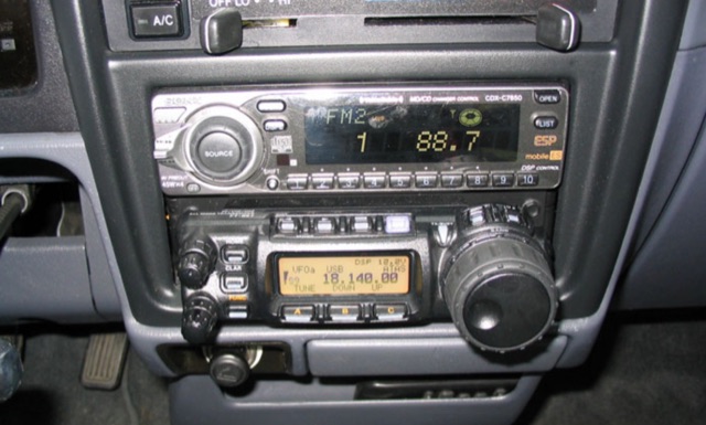 Detailing a Yaesu FT-857 and ATAS-120 installation in a 1997 Toyota Tacoma, the author used Polar Plot to map signal strength. Using a hand truck with a laptop, FT-817, and an Iron Horse antenna, they circled a chalk-outlined 100-foot diameter, revealing potential nulls towards the truck's rear and through the cab, offering insights into antenna performance.
 -
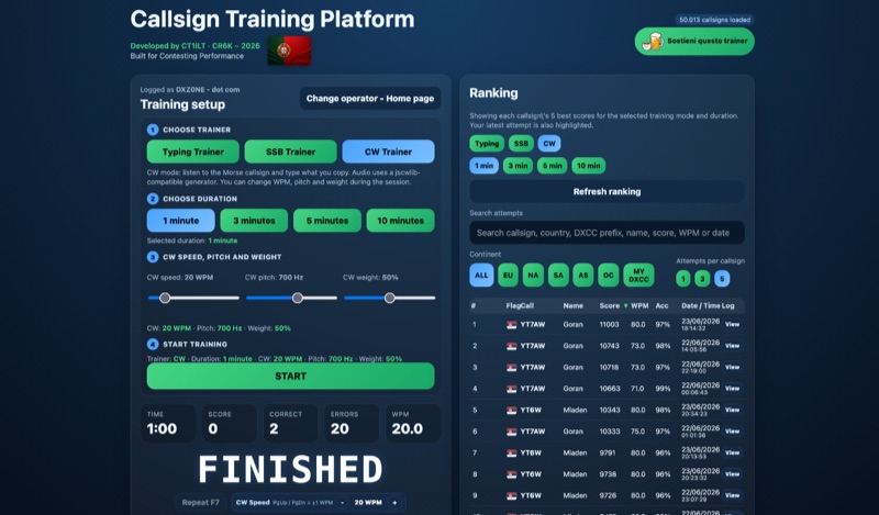 Improving callsign recognition and copying skills is fundamental for effective amateur radio operation, particularly in high-stress environments like contesting or DXing. The CW4EVER Callsign Training Platform provides a focused environment for operators to hone these abilities. It offers three distinct training modes: a Typing Trainer for visual recognition, an SSB Trainer for voice callsign practice, and a CW Trainer for Morse code proficiency, allowing users to tailor their practice to specific operational needs. Operators can select training durations of 1, 3, 5, or 10 minutes, providing flexibility for quick drills or extended practice sessions. For CW training, the platform allows granular control over parameters such as CW speed, adjustable up to **80 WPM**, pitch in Hz, and weight in percentage, enabling personalized learning curves. The system stores operator preferences locally and includes server-side anti-cheat protection, stricter callsign validation, and automatic score archives, ensuring fair competition and persistent training history. Recent enhancements include separate saved CW preferences per operator and _MY DXCC_ ranking positions. The platform also tracks global statistics, including total attempts worldwide, unique callsigns encountered, and total training hours logged, offering a broad perspective on user engagement and progress. These features collectively support operators in achieving higher accuracy and speed in callsign reception.
 -
 This article describes the design and construction of a 4-meter band vertical sleeved dipole antenna, built to complement a newly acquired Yaesu FTDX10 transceiver. The simple yet effective antenna consists of modified coaxial cable housed in weather-resistant plastic conduit, featuring an integrated 8-turn choke coil. Despite common misidentification as an EFHW antenna, this design is actually a sleeved dipole that provides an excellent 50-ohm match across the band, achieving SWR values between 1:1 and 1.1:1. The project demonstrates an economical approach to entering the relatively quiet 4-meter band.
 -
 The project details the construction of a small, portable **CW decoder** built around an Arduino Nano and an LM567 tone decoder circuit. It integrates an OLED display for output and is powered by a 1200 mAh Li-Po battery. The Arduino Nano is programmed with a modified version of the OST Morse Box firmware, originally based on Budd, WB7FHC's work, provided as a HEX file for flashing. The LM567 output connects to Arduino pin D2, while pins A6 and A7 are grounded due to the absence of potentiometers, simplifying the circuit. Standard I2C connections are used for the OLED: SDA to A4 and SCL to A5. The entire assembly, including the Arduino, OLED, and decoder circuit, is mounted on a perfboard to fit precisely within an old cassette tape box. This design emphasizes portability and compact form factor. Parameters for the decoder can be adjusted using a dedicated Windows Control program, offering flexibility in operation. The resource provides practical insights into adapting existing firmware for specific hardware constraints and achieving a self-contained, battery-powered **Morse code** decoding solution.
 -
 This resource presents a non-rigorous evaluation of the front-to-back (F/B) ratio of short Beverage antennas, specifically designed for low-band operation on frequencies such as 160, 80, 40, and 30 meters. The author, VE1ZAC, details the methodology used to measure the F/B ratio, which involves using a Millen Grid Dip Oscillator as a portable signal source. Measurements were taken by switching the antenna direction and recording S Meter and preamp readings to derive gain numbers. The document discusses the challenges faced in achieving accurate measurements and the assumptions made during the process, such as the calibration of S Meter units at 6 dB. This evaluation is particularly relevant for amateur radio operators interested in antenna performance on low bands.
 -
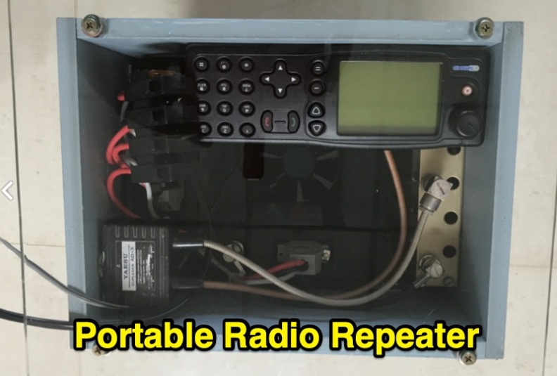 Demonstrates the construction of a portable 2-meter repeater system utilizing a **Yaesu DR-1X** transceiver, configured for both analog FM and C4FM digital voice operation. The design emphasizes portability, robustness, and effective thermal management, incorporating a "wind tunnel" airflow system with a fan to maintain transmit module temperatures at 38 degrees Celsius during continuous operation. The system integrates a diplexer, control head, and is housed in a compact, lightweight case weighing under 8kg, designed for single-person deployment. Covers practical considerations for field deployment, including power sources, antenna types, and the overall system architecture for public service events and emergency preparedness. The resource details the modular "wrap around" construction, showing how components like thermal switches for fan control and Anderson Powerpole connectors are integrated. It highlights the system's ability to provide reliable communications support for club activities and emergency communications.