Search results
Query: used 6 meter
Links: 86 | Categories: 2
-
 The W5GI Mystery Antenna is a versatile multi-band wire antenna designed for amateur radio operators. It covers frequencies from 80 meters to 6 meters, making it suitable for a wide range of operating conditions. The antenna features a low feed point impedance, allowing for easy matching with most radios, whether or not an antenna tuner is used. Its construction is straightforward, requiring only two vertical supports approximately 130 feet apart, making it ideal for hams without towers. Users have reported excellent performance, particularly on the 20-meter band, where it outperforms similar designs like the G5RV. This antenna is unique in its design, incorporating three half waves in-phase on 20 meters, resulting in a six-lobe radiation pattern. Despite its effective performance, the antenna is challenging to model, which adds to its mystique. The W5GI Mystery Antenna has gained popularity among amateur radio enthusiasts worldwide, with many users praising its ease of construction and effectiveness. Whether you're a beginner or an experienced operator, this antenna offers a fun and rewarding project that can enhance your HF capabilities.
 -
 The Super Loop Antenna page, designed by Jim W4FTU, provides detailed information on the RadioWorks \'Superloop III\' antenna as an alternative for operators with limited space. The page discusses the physical variations of the antenna, including dimensions and materials used, as well as its electrical characteristics such as the 30\' ladder line. The content is useful for amateur radio operators looking for antenna options for the 80 and 40 meter bands, especially those with small lots or zoning restrictions. The page is well-organized and informative, making it a valuable resource for antenna enthusiasts.
 -
 This resource provides comprehensive instructions for constructing a 2 element quad antenna specifically designed for the 10, 12, and 15 meter bands. The antenna features a diamond configuration, which offers improved gain compared to a square configuration. The author shares insights into the materials used, including a square-aluminum boom and bamboo poles, along with construction techniques that ensure durability and optimal performance. This project is ideal for amateur radio enthusiasts looking to create their own antennas at home. In addition to construction details, the author discusses the antenna's performance, noting its effectiveness even at a height of 8 meters. The quad antenna reportedly performs comparably to a 3 element yagi, with excellent SWR readings and strong signal reports from European stations. This project is suitable for beginners and offers a cost-effective solution for those interested in enhancing their amateur radio setup with a homemade antenna.
 -
 Presents a practical design for a **crossed-dipole turnstile antenna** specifically engineered for 2-meter Amateur Radio Direction Finding (ARDF) events. The author, WB6RDV, details a robust, omnidirectional, horizontally-polarized antenna, addressing the international ARDF rules requiring such characteristics at a height of two to three meters above ground. This contrasts with the vertical polarization often used in Southern California, highlighting the design's adherence to specific event requirements. The electrical design employs a classic crossed-dipole with a 75-ohm phasing section, resulting in a slight impedance mismatch and an SWR of approximately 1.3:1 with a 50-ohm feedline. Construction utilizes readily available and inexpensive PVC plumbing components and 1/8-inch bronze welding rod for elements. The guide provides step-by-step instructions for mechanical assembly, including drilling element holes at precise 90-degree spacing and preparing the RG-179 matching section. WB6RDV shares insights from his own build experience, discussing the use of plated brass versus aluminum spacers for element attachment and the effectiveness of crimping as an alternative to soldering. The document also covers final assembly, including the integration of ferrite beads as a choke balun and options for weatherproofing and alternative mounting configurations, emphasizing the adaptability of the design for other VHF bands through scaling.
 -
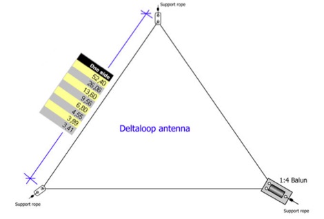
 A multi band inverted delta loop antenna project that can be used from 40 to 10 meters band with full details and analysis of antenna performances on each band, document includes EZNec reports and setup pictures
 -
 The Bruce array is a simple, often-forgotten wire antenna array that is advantageous for 80 and 160 meters, where typical gain antennas are very large. This bi-directional broadside vertical array is only 1\4 lambda high and does not require a ground system. It offers substantially greater SWR bandwidth than the half-square or bobtail curtain. A 4-element Bruce array used by N6LF showed a gain of about 4.6 dB compared to a 1\4 lambda vertical with 8 elevated radials, with a 2:1 SWR bandwidth greater than 400 kHz. The antenna is simple and its dimensions are flexible.
 -
 The article provides detailed instructions on how to build a half-sloper antenna for the 160 meters band. It explains the concept of a sloper antenna and how it differs from a slooper. The article includes practical tips on the construction and installation of the antenna to ensure optimal performance. The intended audience is amateur radio operators interested in building their own antenna for the 160 meters band. The content is informative, practical, and focused on DIY antenna building.
 -
 The total length of this antenna is 41m, height is about 11m, and diameter of element is 2mm. JA7KPI modified this antenna originally used as Inverted-V type of 80m band Dipole. Works on 40 - 80 meters band with acceptable swr.
 -
 Indoor multiband dipole with EZNEC data files for simulation and analysis. Includes details on construction, tuning, SWR plots, and software usage. This page includes two different dipoles, a first version for 20-10 meters and an extended version covering 40-10 meters allowing a full coverage of most used ham radio HF Bands.
 -
 A simple dipole built for two-band operation can be used for portable use and operate 20 and 40 meter bands
 -
 The Adcock antenna has been used for a long time for RDF. It is basically an interferometer.
 -
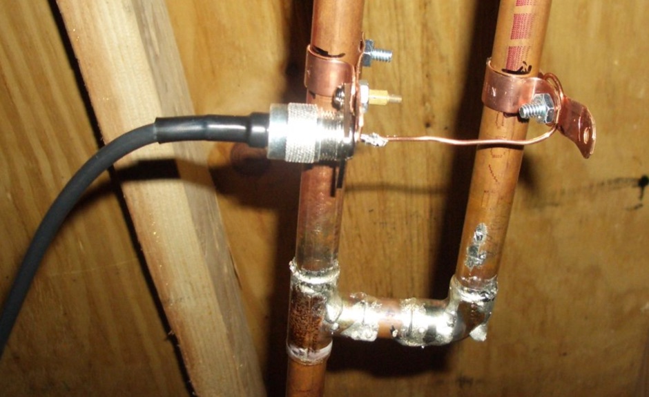
 Constructing a **2-meter** J-pole antenna from readily available copper plumbing components offers a robust and cost-effective solution for VHF operation. This design, dubbed the "Plumber's Delight," functions essentially as a half-wave dipole fed by 50-ohm coax via a **gamma match**. It incorporates a quarter-wave copper tubing support, which, when affixed to a metal mast or tower, enhances forward power in the direction of the radiating elements. The original configuration utilized a small ceramic trimmer capacitor for the gamma match, suitable for up to 10 watts. A subsequent modification replaced this with a 50 pF variable capacitor housed in a plastic enclosure, accommodating higher RF power and improving weather resistance. The antenna elements are secured using a copper "T" fitting, and an SO-239 connector mounts directly to this fitting. Performance includes gain away from the support mast, and tuning is straightforward by adjusting the gamma match capacitor for a 1:1 SWR. The total cost for materials, excluding the capacitor and coax, can be under $10.
 -
 The Joystick antenna was used many years ago as an all band vertical HF antenna under restricted space situations that would cover from 80 meters thru 10 meters with a tuner and was a great commercial success Some hams even had success with it on 160 meters.
 -
 This very large moxon antenna resonate on 80 40 and 10 meters, has been used for CQWW 2006 by a YU team project
 -
 Here are construction plans of a Turnstile antenna that can be used for space communication on the 2 meter amateur radio band. Specifically for 145.80 mHz
 -
 Autotena, a Taiwanese manufacturer, offers a diverse product line focused on RF communication antennas and related accessories. The resource details various antenna types, including **4G/3G LTE wideband high-gain low-profile antennas**, land mobile wideband antennas, fiberglass omnidirectional designs, and GPS mobile and marine antennas. Specific amateur radio offerings include NMO VHF load coil gain antennas, VHF whip gain antennas with PL-259 connectors, and UHF NMO mount antennas with 3dB/5dB gain. The company also produces antennas for CB and 10-meter amateur bands, such as aluminum broadband 26-30MHz antennas and big copper coil broadband 26-30MHz antennas. Additionally, the site showcases **RF amplifiers** for CB, HF, VHF, and UHF bands, including professional-grade base station amplifiers with 100% EIA duty cycle. Handheld antennas, PL-259 type mobile antennas, magnet mount antennas, and external CB speakers are also presented, alongside various mounting kits and cable assemblies.
 -
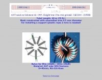 Mesh constructed with enamelled wire 0.5 mm diameter For installing a support (plastic rope 2 mm) is needed. Antenna used on Solomon Isl in 1995 H44/DJ9RB
 -
 Presents _DirLog_, a freeware logging application specifically developed for the 11-meter CB band, catering exclusively to members of the _Alfa Tango Group_. The software facilitates the recording and management of contacts, providing a dedicated tool for CB operators to maintain their station logs. Its development spans from 1997 to 2025, indicating a long-term commitment to its maintenance and evolution by its author, 1AT069 Enio. This specialized logbook offers features tailored for CB operations, allowing users to track their contacts within the 27 MHz band. While primarily focused on CB logging, its structure and functionality could be compared to amateur radio logging software in terms of data entry and retrieval. The exclusivity to Alfa Tango members suggests a community-specific utility, fostering organized record-keeping among its users.
 -
 A multi band delta loop antenna that work on 20 and 40 meters band, that can be used either on 15 meters with poor performances
 -
 Easy home brew 2 meter copper jpole antenna build - under 20 bucks - Hits repeaters 45 miles away. Parts used bought at home depot build time 1 hour.
 -
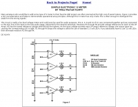 A low-level voltage meter and could even be used for audio purposes.
 -
 Generating Morse code audio files from text input is the primary function of _MorseGen v1.2_, a utility designed for amateur radio operators. The software allows users to specify the tone frequency and words-per-minute (WPM) speed for the generated CW. A key feature is its ability to create a WAVE audio file containing the Morse code, which can then be used in various applications. The program also supports repeating the generated CW sequence at user-defined intervals, making it particularly useful for creating station identification signals or beacons. The practical application of this tool extends to automated station identification, especially for repeaters or digital mode gateways that require a CW ident. By producing a standard _WAVE file_, the output is compatible with most audio playback systems and software. This functionality provides a straightforward method for integrating custom Morse code messages into existing amateur radio setups, eliminating the need for external hardware keyers for simple identification tasks. The adjustable parameters offer flexibility to match specific operational requirements or personal preferences for CW characteristics.
 -
 A 90-foot vertical antenna constructed from **aluminum irrigation tubing** is detailed, focusing on its innovative raising and lowering mechanism. The resource describes a **45-foot ginpole** system, allowing a single operator to erect or lower the antenna in minutes. It covers the mechanical design, including the pivot base, insulated joints for the tubing sections, and guy wire attachment points. The antenna consists of two 30-foot sections of 4-inch tubing and one 30-foot section of 2-inch tubing, stacked with the smaller diameter at the top. The electrical design incorporates PVC "condulet" boxes at the 30-foot and 60-foot points, housing relays to change the effective height for multi-band operation on 160, 80, 40, and 30 meters. Ferrite rod inductive chokes are used for DC control and to tune out gap capacitance. The antenna is fed with 1000 feet of open wire line, connected to a matching transformer comprising stacked toroids and a coaxial/toroidal balun. Grounding is achieved with a 3x3 foot grid of 16-gauge tinned copper wires with soldered crossovers.
 -
 This low power transmitter is developed for ARDF exercising purposes but of course can be used as super QRP transmitter either. With 1 or 2 meter wire as antenna and a ARDF receiver with ferrite-rod antenna the range is about 100m but with better antennas and a 'real' receiver the range is probably much larger.
 -
 W4ZT used this antenna for Field Day and other portable applications. He built them for all bands between 160 meters and 6 meters. You can make them easily using whatever wire you have available and make the insulators from scrap plastic
 -
 A 160 meter antenna with a base loading coil used to tune the two lower frequency segments of the band.
 -
 Details Guglielmo Marconi's foundational contributions to radio communication, highlighting his 1898 Patent **7777** which introduced tuning circuits for independent simultaneous communications. Chronicles the historic transatlantic reception of the Morse code letter 'S' on December 12, 1901, from Poldhu, Cornwall, to St. John's, Newfoundland, a distance of over _3,500 kilometers_. The exhibit showcases early Marconi 10-inch spark transmitters, identical to those used on the _Titanic_, alongside Canadian Marconi crystal detector models. It also features high-end commercial receivers like the IP501, weighing **87 pounds** and originally priced at $595.00, demonstrating the robust construction and technological advancements of the era.
 -
 A short dipole wire antenna for 40 meters band. It is a folded dipole that do not make use of coils and can be used either in horizontal or inverted V configuration
 -
 The Collins TRC-75 autotune linear amplifier, owned by JF2SVU, is presented with a focus on its internal modifications. This QRO amplifier utilizes three 4CX250 tubes in parallel for its final stage, delivering 1 KW output power. Notably, the amplifier achieves full power with only 100 mW of RF input, a characteristic often associated with Collins designs. The original 400 Hz power supply has been converted for easier shack integration, and the entire RF and power supply sections have been rehoused into a compact, clean enclosure. The control unit, positioned above the amplifier, features three meters for individual vacuum tube IP monitoring and a multi-meter on the right. A dedicated 7 MHz receiver, recently completed, is also part of this integrated system. The autotune functionality means the main amplifier unit only requires connections for power, control, and coaxial cables, simplifying its operation. Key components like the 4CX250 tubes and NF capacitors are visible, along with the gearing mechanism for the final tank circuit. A timer and relay system manages high-voltage delay and cooling fan off-delay, although the cooling fan's airflow is noted as somewhat insufficient. A central volume control, which experienced a contact issue, is also highlighted.
 -
 This project details the construction of a **full-sized 40-meter vertical antenna**, born from a renewed interest in 7 MHz operation and a desire for improved effectiveness over simple dipoles. The author, K5DKZ, initially focused on VHF experimentation, which provided an inventory of aluminum tubing and fiberglass spreaders for this endeavor. Before this vertical, K5DKZ utilized an 80/40 meter inverted-vee trap dipole and a 40-meter broadband dipole, but now primarily uses a pair of full-sized, phased, quarter-wave verticals spaced 35 feet apart for serious 40-meter work. The construction involves a base-heavy design for stability, using a 44.5-inch section of 1-1/4 inch steel TV mast driven into 1-3/8 inch aluminum tubing, insulated by a 105-inch section of Schedule 40 PVC pipe. The assembly reaches 31 feet, close to the 32 feet required for a quarter-wavelength on 40 meters, with fine-tuning achieved by winding wire onto a fiberglass spreader. The design is explicitly presented as a foundation for a two-element 40-meter Yagi beam, outlining modifications like substituting aluminum for steel in the base and using an inductive hairpin match for the driven element. The article also discusses tuning considerations for a large 40-meter beam, noting the 100 to 200 kHz upward frequency shift when raised, and suggesting methods for installation on a tower. The author emphasizes the cost-effectiveness and good performance of the monopole approach, especially when multiple verticals are needed.
 -
 Here is a review of the 40 and 80 meter band Double Bazooka antennas as used on the HF shortwave bands.
 -
 Delta 160-meter receiving antenna used at FO0AAA
 -
 80 to 6 meters, 2 KW, designed to be used at heights of only 25 to 45 feet, includes a twenty foot long vertical radiator
 -
 Demonstrates the operational status and reception reports for the SK6RUD/SA6RR QRPP beacons, which transmit on 478.9 kHz, 1995 kHz, 10.131 MHz, and 40.673 MHz. These beacons utilize extremely low power, with the 630-meter beacon operating at approximately 0.1 watt ERP into an L-antenna, showcasing the potential for long-distance contacts under favorable propagation conditions. The site details the specific frequencies and antenna types employed, such as a vertical at 500 kHz and a 1/4 vertical for higher bands. The resource compiles over 10,530 reception reports from amateur radio operators worldwide, logging details such as date, time, band, RST signal report, locator, distance, and receiver setup. Notable long-distance reports include a 500 kHz reception by AA1A-Dave from 5832 km in 2008 and a 10.133 MHz reception by ZL2FT-Jason from 17680 km in 2010, illustrating the global reach of these low-power transmissions. Each log entry provides specific equipment used by the reporting station, including transceivers like the Yaesu FT817, ICOM IC-7300, and various antenna configurations such as coaxial mag loops, inverted Ls, and end-fed wires. The primary objective of the SK6RUD beacons is to challenge conventional notions of power requirements for effective two-way communication, proving that contacts over significant distances are achievable with minimal output. The site also includes a submission form for new reception reports, fostering community engagement and continuous data collection on propagation phenomena across different bands. The detailed logs offer practical insights into real-world propagation characteristics and the efficacy of QRPP operations.
 -
 This resource, originally intended to detail the technical specifications of the **Clover** digital communications mode, currently presents a "Page not found" error. The _Clover_ mode was designed for conveying 8-bit digital data over narrow-band high-frequency radio channels, offering robust performance under challenging propagation conditions. Its design focused on efficient data transfer and error correction, making it suitable for amateur radio operators seeking reliable digital links. The absence of the page prevents analysis of specific technical parameters, such as modulation schemes, data rates, or error correction codes that would have been presented. Historically, Clover offered significant advantages in throughput and reliability compared to earlier digital modes over HF, often achieving higher effective data rates than modes like PACTOR or AMTOR under similar signal-to-noise ratios. Without the content, a direct comparison of its performance metrics or practical application scenarios is not possible.
 -
 This article is about a simple vertical end-fed-half-wave wire antenna for 10 meters that can be used in case of restricted space.
 -
 Presents the construction of a 2-meter **Skeleton Slot Yagi** stack, detailing the design process and practical considerations for VHF operation. The author shares insights from building and testing this antenna, emphasizing its performance characteristics for local and extended range contacts. The project outlines the specific dimensions and materials used, providing a clear path for other radio amateurs to replicate or adapt the design for their own stations. The resource covers the unique aspects of the Skeleton Slot radiator, explaining how its geometry contributes to gain and pattern control. It includes discussions on impedance matching and feedline considerations crucial for optimizing power transfer and minimizing SWR. The article draws on real-world testing, offering practical results that validate the theoretical design. This project serves as a valuable reference for those interested in custom VHF antenna solutions.
 -
 A 220-ft tower that has five catenary lines, each about 500 feet long. Four of these lines, running NE, SE, SW, and NW support four 1/4-wavelength wire verticals used in a 160-meter four-square antenna.
 -
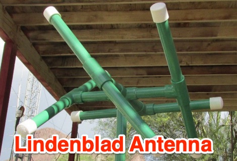 This is a presentation used at OVARC on the LindenBlad antenna construction. The presentation cover several topics about this antenna, from the basic antenna design, to the guide on how to contruct a custom lindenblad antenna for the 2 meters band and and 70 centimenters band.
 -
 New and used test equipment, oscilloscope, spectrum analyzers, multimeters, signal generators, power supplies, network and signal analyzers and more
 -
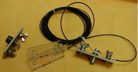
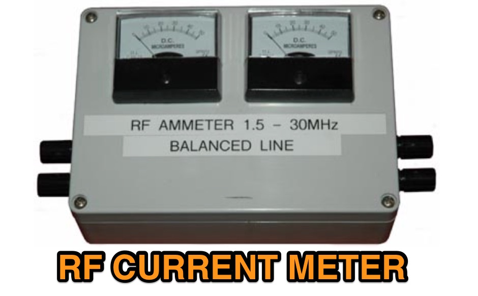 This R.F. current meter was developed to assist in measuring line currents in balance feed lines as used in the All Band HF Antenna.
 -
 KB9AMG's Top WSPR Spots presents a focused online tool for monitoring **2-way WSPR reports**, specifically detailing propagation data from February 2026 through March 2026. This resource aggregates _WSPRnet_ data, allowing radio amateurs to observe weak signal propagation conditions across various bands. The interface is straightforward, presenting callsigns, frequencies, signal-to-noise ratios, and distances for each reported contact, which is crucial for understanding current band openings and signal paths. The utility of this WSPR spotter lies in its ability to quickly visualize global propagation. Users can identify active stations and assess signal viability over long distances, with reports often showing contacts spanning thousands of kilometers. For instance, a typical WSPR report might indicate a signal from Europe reaching North America with a _SNR_ of -25 dB, demonstrating effective low-power communication. This data is invaluable for planning DX operations or evaluating antenna performance under actual propagation conditions.
 -
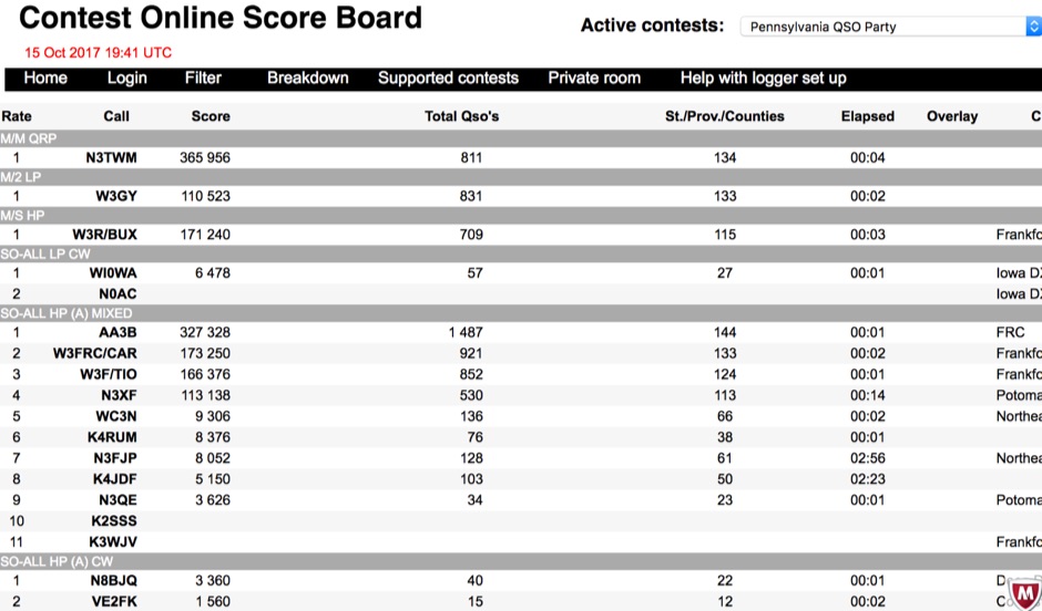 Aggregating real-time contest scores, this online scoreboard serves as a central hub for participants and spectators to monitor live progress during amateur radio competitions. It directly interfaces with widely used contest logging programs, collecting score data as operators make contacts. The platform then processes and displays these scores on dedicated contest pages, offering an immediate overview of standings. Supporting a diverse range of **DX contests**, the system accommodates various operating modes and rulesets. It facilitates score tracking for events like the YB DX RTTY, RSGB Commonwealth (BERU), EA PSK63, and the South America 10 Meter contest, among others. This functionality allows contesters to gauge their performance against competitors instantaneously, fostering dynamic participation. The scoreboard's integration with multiple contest log software applications ensures broad compatibility, making it accessible to a significant portion of the contesting community. It provides a crucial service by centralizing score visibility, enhancing the competitive experience for **amateur radio operators** worldwide.
 -
 Since 1956, E-Z-Hook has been manufacturing electronic test accessories used for test and measurement purposes throughout multiple industries. Test probes, multimeters, coax cables, adapters
 -
 A 7 dB directional gain is reported for this portable VHF Yagi antenna design, which utilizes cut metal tape measure sections for its elements. The resource details the construction process for a 2-meter band antenna, emphasizing its ease of build and portability. It specifically mentions the design's suitability for radio direction finding (RDF), fox hunting, and communication with satellites and the International Space Station (ISS), highlighting its practical applications for amateur radio operators. The construction cost is estimated at under $20, with potential for even lower expense if salvaged materials like old tape measures and PVC pipes are used. The article references _Joe Leggio's_ (WB2HOL) original design, noting specific alterations made by the author. It also compares this design to other DIY Yagi antennas, including _FN64's_ 2-meter band and _manuka's_ 70-cm band tape measure Yagis, underscoring its unique combination of simplicity, portability, and effective performance with a 1:1 SWR achievable on the 2-meter band.
 -
 The antenna in this project is a modification of the techniques used to design a multiband fan type dipole with little or no tuning involved having a total space of 105 feet
 -
 Constructing a dip oscillator provides radio amateurs with a fundamental piece of test equipment for resonant circuit analysis. This particular design, adapted by VK3YE from a concept by _Drew Diamond VK3XU_, details a practical build using readily available components. The unit incorporates four plug-in coils, covering a frequency range from **2.6 MHz to 55 MHz**, mounted on 5-pin DIN plugs for versatility. A salvaged two-gang air dielectric variable capacitor, fitted with a vernier reduction drive, serves as the tuning mechanism, with the smaller gang optimizing bandspread at higher frequencies. In practical application, the dip oscillator is used by setting the meter needle to approximately two-thirds scale. When the instrument's coil is brought near a tuned circuit under test, a noticeable dip in the meter reading indicates resonance. This allows for precise measurement of resonant frequencies in antennas, filters, and other RF circuitry, proving invaluable for homebrewing and troubleshooting. The design emphasizes short wire runs for stable operation, particularly at the higher end of its operational range.
 -
 Makers of the The Polar Explorer transmitter, which operates on 9 HF bands from 160 through 10 meters and is capable of 500 watt peak output power on SSB, CW, AM, FM and RTTY. It is intended to be used in conjunction with a transceiver.
 -
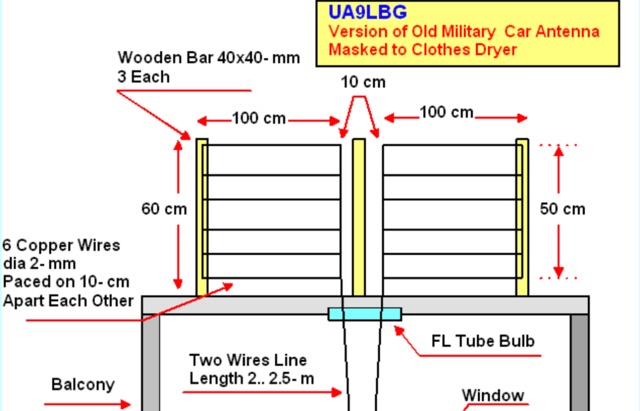 The antenna almost repeat the design of the Car Antenna however instead of aluminum tubes it was used copper wire in plastic insulation in diameter of 2- mm (12 AWG).
 -
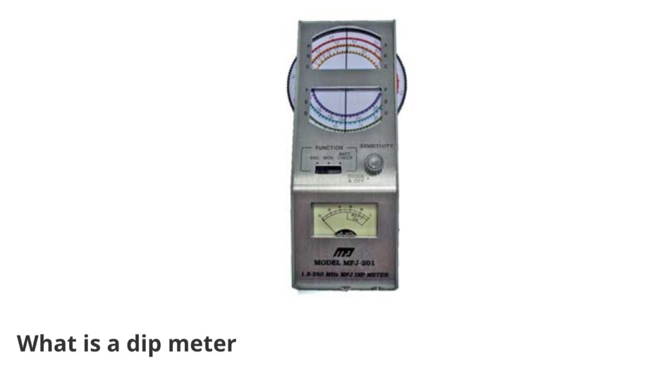 All the essentials about the Dip Meter or Grid Dip Oscillator used for many RF measurements including detecting resonance, locating RF emissions, and making many RF measurements.