Search results
Query: 6 meters
Links: 977 | Categories: 19
Categories
- Manufacturers > Test Equipment > Multimeters
- Manufacturers > SWR Meters
- Technical Reference > SWR Meters
- Manufacturers > Wattmeters
- DX Resources > Beacons > 6 meters beacons
- Antennas > 80M
- Technical Reference > Arduino
- Radio Equipment > HF Vertical Antenna > Cushcraft R8
- Manufacturers > Test Equipment > Frequency Counter
- Antennas > Halo
- Manufacturers > Ham Shack Accessories
- Radio Equipment > HF YAGI Antennas > Hy-Gain TH3JR
- Antennas > Morgain
- Technical Reference > Test Equipment > Multimeter
- Manufacturers > Test Equipment > Power Meter
- Technical Reference > Power Meter
- Manufacturers > Test Equipment
- Technical Reference > Test Equipment
- Technical Reference > Components > Toroids
-
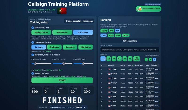 Improving callsign recognition and copying skills is fundamental for effective amateur radio operation, particularly in high-stress environments like contesting or DXing. The CW4EVER Callsign Training Platform provides a focused environment for operators to hone these abilities. It offers three distinct training modes: a Typing Trainer for visual recognition, an SSB Trainer for voice callsign practice, and a CW Trainer for Morse code proficiency, allowing users to tailor their practice to specific operational needs. Operators can select training durations of 1, 3, 5, or 10 minutes, providing flexibility for quick drills or extended practice sessions. For CW training, the platform allows granular control over parameters such as CW speed, adjustable up to **80 WPM**, pitch in Hz, and weight in percentage, enabling personalized learning curves. The system stores operator preferences locally and includes server-side anti-cheat protection, stricter callsign validation, and automatic score archives, ensuring fair competition and persistent training history. Recent enhancements include separate saved CW preferences per operator and _MY DXCC_ ranking positions. The platform also tracks global statistics, including total attempts worldwide, unique callsigns encountered, and total training hours logged, offering a broad perspective on user engagement and progress. These features collectively support operators in achieving higher accuracy and speed in callsign reception.
 -
 This page provides a detailed review and installation experience of a new 6 and 2 meter dual band Yagi antenna. The author shares insights on the purchase process, shipping, assembly, and performance of the antenna in their backyard setup. The content is useful for hams looking for information on dual band Yagi antennas, especially those interested in improving their contest operations or backyard installations. The author's personal experience and challenges with mounting the antenna on a small push-up mast are also discussed.
 -
 This resource details the construction and performance of a compact broadband magnetic loop antenna designed for portable receiving applications with devices like the _ATS MiniRadio_. The antenna utilizes approximately 3 meters of 0.5–1 mm copper wire wound in two turns on a rhomboidal wooden frame, measuring 50 cm by 70 cm. It connects via a modified 9:1 unun, where the primary center tap is isolated from ground to improve common-mode noise rejection. The design provides untuned operation across a frequency range from the longwave band up to approximately 25 MHz. Performance characteristics include observable directivity for noise suppression and the ability to connect directly to a radio or via a 50 coaxial cable for remote operation. The article specifies the unun's 3:1 turns ratio and its SMA output for connectivity. The methodology focuses on practical construction and observed reception quality.
 -
 This is a theoretical look at propagation on 630-Meters and 2200-Meters using ray tracing software. It expands on the brief discussion in the ARRL Handbooks. The Earth's magnetic field affects 630-Meter and 2200-Meter band propagation. Lower ionization reduces absorption, aiding low-frequency propagation. Differences exist between bands, limited daytime sky-wave propagation. Sunrise/sunset show promise, yet mechanisms are unclear. Ducting possible at night in specific conditions. Negative ions enhance propagation. Inefficient antennas and high man-made noise are anticipated. Groundwave propagation is significant on 2200-Meters.
 -
 This report details a modification of a Diamond V2000 antenna, replacing its original two 0.50 m radials with two 1.55 m radials. Initial M5-threaded rods failed to fit; the housing required M6 threads. Custom radials were made using 8 mm OD aluminium tubing and M6-threaded stainless steel ends, secured with nuts machined to 9 mm. SWR issues on 6 m (>2:1) were largely due to a poor counterpoise connection, resolved during reassembly. NanoVNA measurements showed no adverse effects on 2 m or 70 cm. The final setup retains the two 1.55 m radials and original counterpoise. Other operators reported SWR degradation with similar mods—sometimes fixed by adding capacitance—but this was not observed here.
 -
 YAGio 1.01 is a Windows-based software for designing DL6WU long Yagi antennas on VHF and UHF frequencies. It supports Windows 2000, XP, Vista, 7, and likely 8. Using keyboard commands, users input specifications such as frequency, gain, and element diameters, and YAGio generates the design. You can download latest Yagio version from this page. Results can be saved in YIO, NEC, YAG, MMA, and YC6 formats, or printed directly.
 -
 This project outlines a simple, cost-effective 40m band HF dipole antenna design, ideal for beginners. Constructed with insulated copper wire and a 1:1 balun, it offers a 50-ohm impedance, suitable for both 40m and 15m bands due to the harmonic relationship. Calculations account for a K factor, ensuring optimal length and performance. Antenna modeling with 4NEC2 confirms practical access to both bands, though real-world results may vary. Lightweight materials and straightforward assembly make it an accessible and versatile amateur radio solution.
 -
 The project details the construction of a GM3OXX OXO transmitter, designed to accommodate **FT-243 crystals** using 3D-printed FX-243 holders from John KC9ON. It presents specific frequency adjustments, noting a 7030 KHz HC-49/s crystal could be tuned from 7029.8 KHz to 7031.7 KHz with an internal 45pF trimmer capacitor. The build incorporates a modified keying circuit to prevent oscillator run-on key-up and includes a TX/RX switch for sidetone via a connected receiver, with the transmitter output routed to a dummy load on receive. Practical construction aspects are thoroughly covered, including the process of cutting a rectangular opening in a diecast enclosure for the FT-243 socket and the selection of a **low-pass filter** (LPF) based on the QRP Labs kit, derived from the W3NQN design. The author achieved approximately 800mW output power from a 14.75V supply, measured with an NM0S QRPoMeter, using a 16.5-ohm emitter resistor in the 2N3866 final stage. The article also touches upon the potential for frequency agility across the 40M band using multiple FX-243 units with various crystals. The narrative includes a brief diversion into Bob W3BBO's recent homebrew projects, such as his Ugly Weekender MK II transceiver, highlighting the enduring appeal of classic QRP designs. The author reflects on the personal satisfaction derived from building RF-generating equipment, irrespective of DX achievements, and shares experiences of making local contacts with the 800mW OXO transmitter on 40 meters.
 -
 The project details the construction of a small, portable **CW decoder** built around an Arduino Nano and an LM567 tone decoder circuit. It integrates an OLED display for output and is powered by a 1200 mAh Li-Po battery. The Arduino Nano is programmed with a modified version of the OST Morse Box firmware, originally based on Budd, WB7FHC's work, provided as a HEX file for flashing. The LM567 output connects to Arduino pin D2, while pins A6 and A7 are grounded due to the absence of potentiometers, simplifying the circuit. Standard I2C connections are used for the OLED: SDA to A4 and SCL to A5. The entire assembly, including the Arduino, OLED, and decoder circuit, is mounted on a perfboard to fit precisely within an old cassette tape box. This design emphasizes portability and compact form factor. Parameters for the decoder can be adjusted using a dedicated Windows Control program, offering flexibility in operation. The resource provides practical insights into adapting existing firmware for specific hardware constraints and achieving a self-contained, battery-powered **Morse code** decoding solution.
 -
 VE1ZAC's analysis details the performance of **MFJ927** and **SGC239** autotuners with portable HF vertical antennas, specifically comparing 31 ft and 43 ft configurations. The resource originated from challenges encountered during a Maritime QSO Party roving operation, necessitating a lightweight and easily deployable antenna system. Target bands for the contest included 80, 40, 20, 15, and 10 meters, with a maximum power handling of 100 W CW. The author utilized a 30-foot carbon fiber push-up pole to support a vertical wire element, noting its 2 lb weight and reliability. EZNEC modeling was employed to predict performance, showing favorable results for a 30-foot vertical with elevated radials, particularly on 40 and 20 meters. Feedpoint impedance measurements, taken with an AIM4170C, are presented for various HF bands, both with and without a 41-foot RG6 stub designed to reduce reactance on 80 and 20 meters. The stub significantly improved matching on these bands, easing the tuner's workload. Operational tests revealed issues with the MFJ927's reliability during contest setup, leading to reliance on the K3's internal tuner. The SGC239, tested post-contest, performed flawlessly. A detailed side-by-side comparison covers mechanical aspects, connection options, power bias, impedance range, board quality, and documentation. Modifications to the MFJ927, including a new aluminum case, white paint for heat reduction, and upgraded impedance-measuring resistors, are also described.
 -
 The St Paul Island CY9C DXpedition is scheduled for August 26, September 5, 2024. All bands from 160-6 meters are planned.
 -
 This resource presents a non-rigorous evaluation of the front-to-back (F/B) ratio of short Beverage antennas, specifically designed for low-band operation on frequencies such as 160, 80, 40, and 30 meters. The author, VE1ZAC, details the methodology used to measure the F/B ratio, which involves using a Millen Grid Dip Oscillator as a portable signal source. Measurements were taken by switching the antenna direction and recording S Meter and preamp readings to derive gain numbers. The document discusses the challenges faced in achieving accurate measurements and the assumptions made during the process, such as the calibration of S Meter units at 6 dB. This evaluation is particularly relevant for amateur radio operators interested in antenna performance on low bands.
 -
 Assessing the ICOM IC-R9000 communications receiver, this review details its operational parameters and user experience for radio enthusiasts. Introduced in 1985, the IC-R9000 covers a broad frequency spectrum from 0.1 MHz to 1999.8 MHz, making it suitable for a wide array of listening activities from medium wave (MW) to VHF/UHF. Key performance metrics include a dynamic range of **102 dB** with the narrow SSB filter, crucial for discerning weak signals in crowded bands, and its substantial physical dimensions of 424 x 150 x 365 mm and 20 kg weight. The receiver's architecture supports various modes, though it notably lacks synchronous detection, a feature often desired for improved AM reception under fading conditions. It incorporates 1000 memory channels and robust scanning capabilities, facilitating efficient monitoring across its extensive frequency range. This analysis provides insights into the IC-R9000's capabilities and limitations, offering a historical perspective on a significant piece of amateur radio and shortwave listening hardware.
 -
 The **Yaesu FRG-100** shortwave receiver, introduced in 1992, operates across a frequency range of 50 kHz to 30 MHz, accommodating AM, LSB, USB, and CW modes, with an optional narrow-band FM capability. Its physical dimensions are 238 x 93 x 243 mm, with a weight of 3 kg, making it suitable for both portable and fixed station deployments. Power options include standard mains voltage or 12VDC, providing operational flexibility for diverse listening environments. The front panel integrates a manual tuning knob, an analogue signal strength meter, and an LCD display that provides critical information such as frequency, operating mode, memory channel, and time. Users can configure various operational parameters, including tuning steps and bandwidth filters, to optimize reception for specific signals. This review highlights the FRG-100's straightforward interface and its utility for shortwave listening enthusiasts. The design emphasizes user-friendly adjustments for settings, which contributes to its appeal among those interested in general coverage reception.
 -
 Over 200 distinct 2-meter band amateur radio repeaters are cataloged for Australia, providing essential operational data for VHF communication. Each entry specifies the repeater's output frequency, often including the input tone (e.g., **91.5 Hz** or **123.0 Hz** CTCSS) and the repeater's callsign (e.g., _VK2RSC_, _VK3RHF_). Locations are precisely noted, frequently referencing specific towns, mountains, or geographical features such as "Kinglake, Kangaroo Ground" or "Adaminaby, Mars Hill." The resource also indicates various digital modes and linking capabilities where applicable, such as "FMEchoLinkFusionWIRES-X" or "DMR," alongside standard FM operation. This detailed listing facilitates local and regional VHF communication, enabling hams to program their transceivers accurately for repeater access. The data is presented in a clear, tabular format, making it straightforward to identify repeaters by frequency and location.
 -
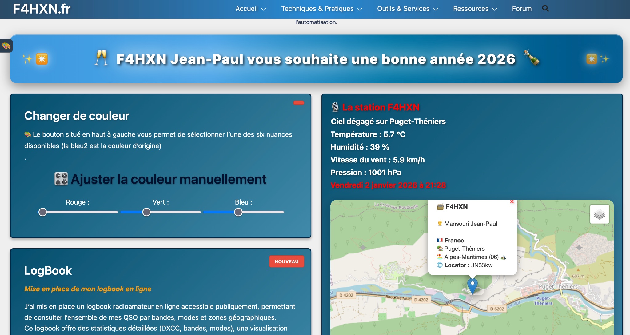 Demonstrates various technical projects and tutorials for amateur radio operators, focusing on digital modes, monitoring, and station setup. It covers topics such as implementing a _WSPR_ station, setting up ADS-B reception, configuring a _DXSpider_ cluster, and utilizing monitoring tools like Prometheus and Grafana. The resource provides practical guides for integrating modern IT solutions with ham radio activities, including Docker and Linux environments for radio applications. This site also features a publicly accessible online logbook, offering detailed statistics on QSOs by band, mode, and geographical zone, with visual mapping of contacts. It includes a comprehensive amateur radio lexicon, explaining hundreds of terms, and provides a real-time display of the F4HXN station's local weather conditions. The resource also aggregates information on upcoming ham radio events and offers a **SWR simulator** for antenna analysis, allowing users to visualize ROS changes based on frequency and antenna parameters.
 -
 The author discusses ways to display VHF and higher bands using a K3/10 as transverter, NooElec Upconverter, SDR, and SDR-Console. He observed that the results were remarkable, with the tuned frequency visible at +/-100kHz. The K3 Interface Option (KXV3A) produces a buffered IF output at 8.213MHz, which is received using a NooElec NESDR SMArt SDR dongle and Ham It UP Upconverter. The SDR-Console program is utilized, with Omnirig synchronizing the SDR and K3. To configure the system, particular parameters are required, such as adjusting the IF frequency to 133.213MHz (125MHz + IF frequency) and inverting the spectrum. The Panadapter demonstrated ES activity at 10m, and modest software tweaks may be required for improved performance.
 -
 Enables digital radio transceivers to function as versatile data communication nodes, supporting applications like _Reticulum_ networking, messaging with Sideband, and acting as a LoRa-based KISS-compatible amateur radio TNC. This firmware transforms off-the-shelf development boards into powerful, long-range data radios, facilitating robust communication over significant distances, potentially achieving **hundreds of kilometers** with optimal setups. It supports a range of hardware, including unsigned.io's Handheld RNodes (v2.x and v1.x), LilyGO T-Beam v1.1, LilyGO LoRa32 (v2.0, v2.1), and Heltec LoRa32 v2 devices. Compatibility extends to transceiver modules utilizing Semtech SX1276, SX1278, SX1262, SX1268, and SX1280 chips, provided they have an SPI interface and exposed interrupt pins. Installation is streamlined via the `rnodeconf` utility, part of the `rns` package, simplifying the flashing process for users. The project operates under the GNU General Public License v3.0, promoting open development and user freedom. It encourages community involvement in building and deploying RNodes for various purposes, from personal communication to establishing resilient, decentralized networks. The firmware's design emphasizes flexibility, allowing for diverse configurations to suit specific operational requirements.
 -
 Demonstrates the construction of an active loop converter specifically designed for the Low Frequency (LF) bands, addressing common localized noise interference in LF reception. The design integrates a sharply tuned circuit and a tuned loop antenna, utilizing the loop as the sole tuned inductive element. By applying positive feedback, the converter significantly increases the loop's effective Q, achieving factors between 1000 and 2000, which sharpens tuning and reduces noise. The circuit employs an _NE602_ mixer stage, feeding its output to an HF receiver, with a crystal-locked local oscillator at 4 MHz. A 20-turn, 0.8-meter square loop antenna with 500 uH inductance is detailed, connected via 2 meters of figure 8 flex cable. The converter offers three selectable frequency bands: 195-490 kHz, 150-220 kHz (including the New Zealand amateur band), and 128-160 kHz (covering the European amateur band). Performance measurements indicate an effective 3dB bandwidth of approximately 100 to 200 hertz at 200 kHz. The article provides insights into component selection, including an _LF353_ op-amp and a trifilar wound transformer on a ferrite core. Sensitivity figures are presented, showing 7.5 uV of converted output per 1 uV/meter signal strength into a 50-ohm load, or 37.5 uV into an _FRG7_ receiver, highlighting its capability to extract weak signals from noise.
 -
 The 4m Slim Jim antenna project provides a construction guide for a low-cost, high-performance aerial designed specifically for the 70 MHz FM band. This design achieves a 1:1 SWR across the 4m FM band with straightforward adjustment of the feed point, utilizing RG-58 coax. Its low angle of radiation contributes to effective signal propagation. Construction involves using plastic knitting needles as spreaders and a telescopic fishing pole for support, with components secured using two-part epoxy. Annealed bare single-core copper wire forms the radiating element. The setup process includes raising the antenna at least 3 meters above ground for tuning, adjusting the RG-58 feed point for optimal SWR, and then soldering connections. Waterproofing is achieved with yacht varnish. The design emphasizes low wind resistance for durability, making it suitable for exposed outdoor installations. A PDF construction diagram is available to supplement the written instructions.
 -
 Home page of CE3SAD with information on his activity and progress expecially on the six meters band with audio recordings of some 50 MHz QSOs.
 -
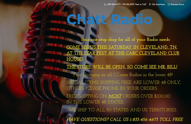 Presents an online retail platform for amateur radio operators, showcasing a diverse inventory of equipment and accessories. The site lists popular transceivers such as the _Icom IC-7300_ and _Icom IC-7610_, alongside various antenna solutions including base, HT, mobile, and end-fed designs. Operators can find coaxial cable, including bulk options and products from "The Wire Man," essential for shack setup. The platform also stocks crimping and stripping tools, adapters, and power supplies, crucial for station maintenance and construction. Test equipment like _RigExpert Analyzers_ and accessories such as Daiwa meters and _West Mountain Radio_ Power Poles are available. Additionally, the site offers software from _Ham Radio Deluxe_ and _RT Systems_, catering to logging and radio programming needs. Shipping policies include free shipping on C.Crane Radios and most orders over $100.00 within the lower 48 states, providing clear purchasing incentives.
 -
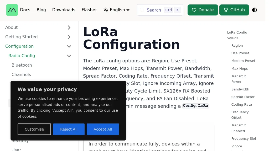 The Meshtastic documentation outlines critical LoRa configuration parameters for node operation, emphasizing regulatory compliance. It details settings such as Region, Modem Preset, Max Hops, Transmit Power, Bandwidth, Spread Factor, Coding Rate, and Frequency Offset. A comprehensive table provides region codes, frequency ranges (e.g., US **902.0 - 928.0 MHz**), duty cycles, and power limits (e.g., EU_433 **12 dBm**) for numerous countries, including the US, EU, China, and Japan, alongside a 2.4 GHz band option. It explicitly states that devices within a mesh must share identical _Region_ and _Modem Preset_ settings for full communication. Modem Presets, like _LONG_FAST_ (the default), optimize for either speed or range, directly impacting network congestion and message delivery delay. For instance, SHORT_TURBO offers the fastest speed and shortest range, while VERY_LONG_SLOW provides the longest range but is less reliable for mesh formation. The document also highlights specific duty cycle limitations, such as the 10% hourly limit for EU_433 and EU_868 regions, and provides command-line interface (CLI) examples for configuring these parameters.
 -
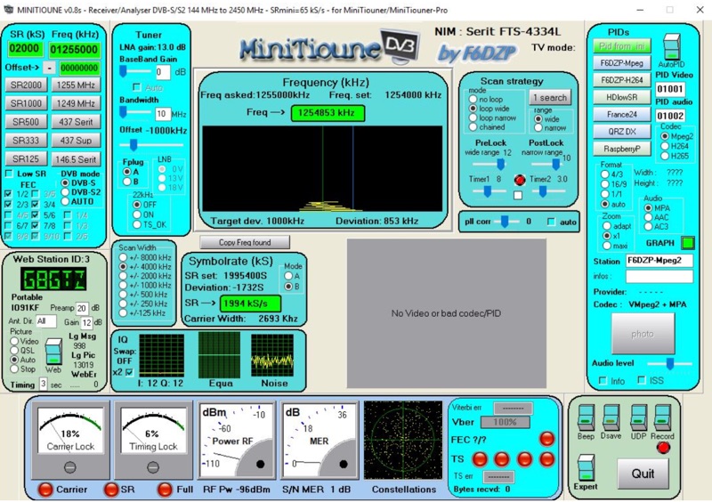 Receiving Digital Amateur Television (DATV) signals requires specialized software to interface with hardware tuners and decode the video stream. The _MiniTioune_ software, developed by F6DZP, serves this purpose, providing a Windows-based application for DVB-S and DVB-S2 reception and analysis. It is designed to work in conjunction with _MiniTiouner_ hardware, enabling hams to monitor DATV transmissions, including those from the QO-100 geostationary satellite. The resource outlines the initial setup process, including connecting the MiniTiouner hardware via a high-quality USB2 mini cable and running diagnostic test software. It details how to configure essential parameters such as symbol rate (SR), FEC rate, and DVB mode for various signal sources, from domestic satellite dishes to local DATV transmitters. Troubleshooting steps for common issues like "no video displayed" are also provided, often pointing to corrupted software filters or incorrect _Auto PID_ settings. Advanced features like the Web monitor for remote signal reporting and integration with _VLC_ media player for more tolerant decoding of non-DVB compliant signals are covered. The document also references a comprehensive user guide by W6HHC for the _MiniTiouner-Express_ system, which utilizes the same software, offering further in-depth assistance for operators.
 -
 The Alfa Alfa (AA) DX Group, established on March 1, 1974, in the Netherlands, is presented as the pioneering Dutch 27mc DX group. It details the group's historical significance, particularly its revolutionary use of the '000' club callsign (19AA000) which influenced international 11-meter group callsign structures. The resource outlines the group's re-establishment in 2024, inviting new active CB operators and _Short Wave Listeners_ (SWL) to join its ranks, emphasizing a free worldwide membership model. Membership requirements are specified, focusing on active participation with an assigned AA callsign. The group provides QSL card management services, with options for direct QSL requests requiring **3 USD** and a Self-Addressed Envelope, or **4 USD** via PayPal for expenses. It also mentions upcoming initiatives like an _AA DX Contest_ and an award program, with sections for certificates and plaques currently under construction. The site also lists useful CB resources, including an 11M DX Cluster and an 11M Callsign Database, and provides contact information for the founder, 19AA001 Mr. Theo, and the Worldwide QSL Manager, 178AA001 Mr. Emil, based in Bulgaria.
 -
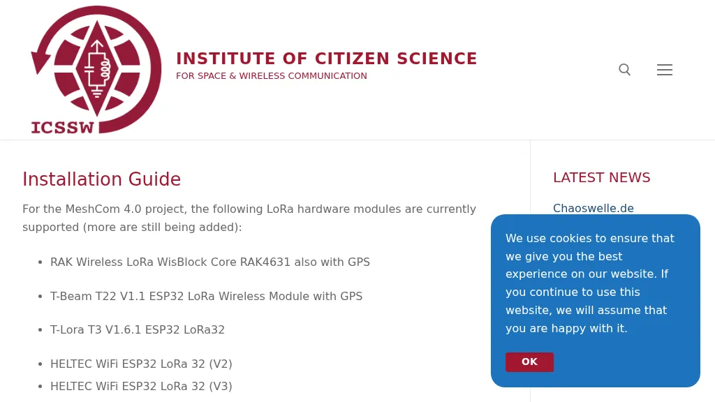 The resource provides a technical installation guide for _MeshCom 4.0_, an amateur radio mesh networking project utilizing LoRa hardware modules. It systematically covers the setup process for several supported devices, including the RAK Wireless LoRa WisBlock Core RAK4631, T-Beam T22 V1.1, T-Lora T3 V1.6.1, HELTEC WiFi ESP32 LoRa 32 (V2 and V3), HELTEC E290, ESP32 / E22 modules, and the T-deck from Lilygo. The guide specifies support for the **EU433** frequency band, ensuring amateur radio compatibility, and details the use of an online flash tool for ESP32 modules and an embedded drive for RAK modules. It further describes accessing the MeshCom 4.0 Dashboard and Map functionalities, crucial for network visualization and management. Firmware configuration for ESP32 modules is meticulously outlined, covering essential parameters such as setting callsigns, country codes, and gateway parameters via a serial console like PuTTY. Commands for activating gateway mode, setting internet IP addresses, and configuring WLAN SSID and password for modules with WLAN capability are provided, enabling modules to function as either clients or gateways within the MeshCom network.
 -
 Over 44,000 square kilometers of Scotland's natural beauty provide a unique backdrop for the _GMFF_ award program. Designed for amateur radio operators who thrive on portable operations, this program encourages activators to set up stations in designated flora and fauna areas. Participants engage in _SSB_ and _CW_ modes, making contacts from these scenic locations, which are part of the _WorldWide Flora and Fauna_ network. Activators and chasers alike benefit from the program's structure, which awards points for successful contacts. The _GMFF_ program is part of a larger global initiative, allowing operators to contribute to conservation awareness while enjoying their hobby. With a focus on environmental preservation, the program aligns amateur radio activities with ecological interests, promoting responsible and sustainable operating practices. The program's website provides resources for participants, including maps of designated areas and guidelines for operation. By participating, operators not only enjoy the challenge of portable operation but also support the conservation of natural habitats. The _GMFF_ program thus combines the thrill of amateur radio with a commitment to environmental stewardship.