Search results
Query: antenna
Links: 2503 | Categories: 254
This query is too generic. Please try adding an additional term to focus your research.
Categories
- Antennas > 20M > 20 meter Dipole Antennas
- Antennas > 20M > 20 meter Vertical Antennas
- Antennas > 20M > 20 meter Yagi antennas
- Antennas > 40M > 40 meter Delta Loop Antennas
- Antennas > 40M > 40 meter Dipole Antennas
- Antennas > 40M > 40 meter Loop Antennas
- Antennas > 40M > 40 meter Magnetic Loop Antennas
- Antennas > 40M > 40 meter Vertical Antennas
- Antennas > 40M > 40 meter Yagi Antennas
- Antennas > 6M > 6 meter J-Pole Antenna
- Antennas > 6M > 6 meter Moxon Antennas
- Antennas > 6M > 6 meter Yagi Antennas
- Manufacturers > Antennas > HF > Active antennas
- Software > Antenna analysis
- Manufacturers > Antenna Analyzers
- Radio Equipment > Antenna Analyzers
- Antennas > Antenna Books
- Antennas > Antenna Calculators
- Antennas > Theory > Antenna Gain
- Technical Reference > Antenna Launcher
- Manufacturers > Antenna Launcher
- Manufacturers > Antenna Masts and Mounts
- Shopping and Services > Antenna Mount
- Manufacturers > Antenna Parts
- Shopping and Services > Antenna Parts
- Technical Reference > Antenna Rotator
- Manufacturers > Antenna Rotators
- Software > Antenna rotor control
- Technical Reference > Antenna Switch
- Manufacturers > Antenna Switches
-
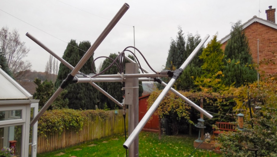 An homebrew Lindenblad antenna designed specifically for LEOs reception.
 -
 The X80 multi-band HF vertical antenna, a commercial iteration of the Rybakov design, exhibits a physical length of 5.5 meters, or approximately 18 feet, and is constructed from aluminum tubing. It operates as a non-resonant vertical, requiring an external antenna tuner for impedance matching across its intended operating frequencies. The antenna's design incorporates a 1:4 UNUN at its base, facilitating a nominal 50-ohm feed point impedance for the coaxial cable. Performance observations indicate effective operation on 40 meters, 20 meters, 15 meters, and 10 meters, with reduced efficiency on 80 meters and 160 meters due to its relatively short electrical length for these lower bands. Comparative analysis with a G5RV dipole and a half-wave end-fed antenna reveals the X80 offers a lower take-off angle, beneficial for DX contacts, particularly on the higher HF bands. Field tests conducted with an Icom IC-706MKIIG transceiver and an LDG AT-100ProII autotuner demonstrate the X80's ability to achieve acceptable SWR across 80m through 10m. The antenna's compact footprint and ease of deployment make it suitable for restricted spaces or portable operations, though its performance on 80 meters is noted as a compromise compared to full-size resonant antennas.
 -
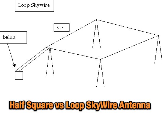 An article at NFARL web site about differences in setting up a half-square antenna versus a Loop Skywire by W4QO
 -
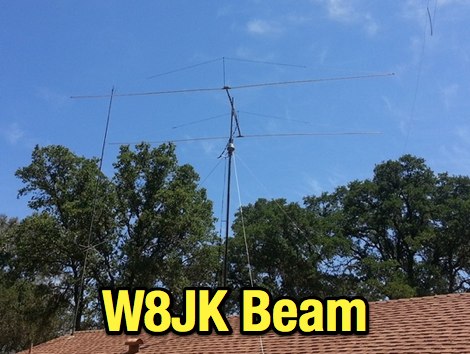 A compact 2 element W8JK beam antenna for 20M to 10M bands by AF6SA
 -
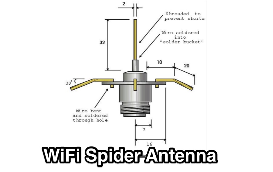 Quarter wave omni-directional spider antenna for 2.4GHz 802.11b
 -
 A simple antenna analyser for the HF spectrum with a built-in signal generator with 3-digit LED frequency display.
 -
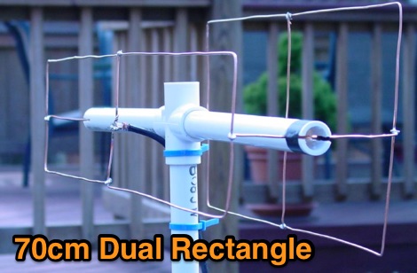 The antenna described here is a direct-connect dual-rectangle beam for use on 70 cm between 440 and 450 MHz
 -
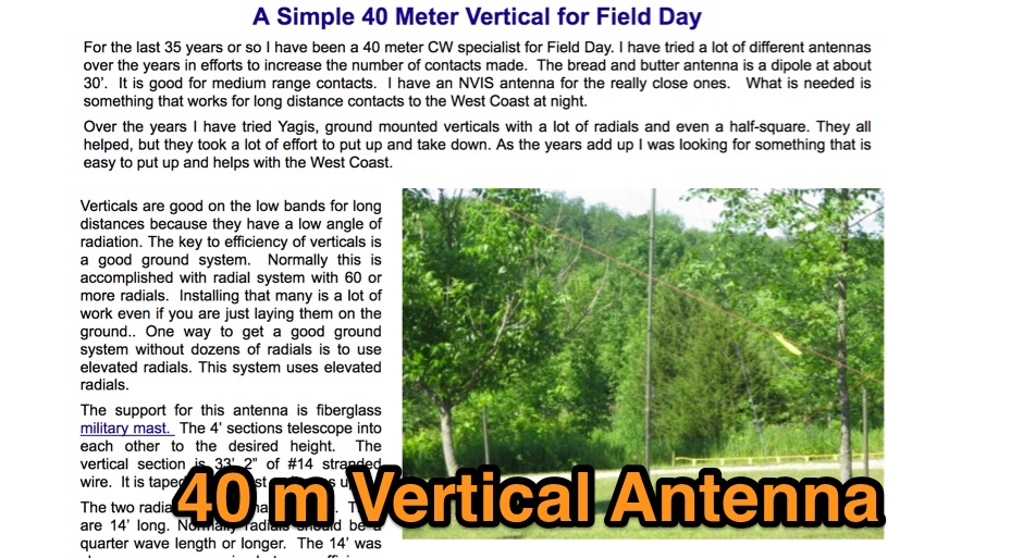 A dipole antenna for 7 MHz support for this antenna is fiberglass military mast
 -
 Comments received from QRP-L members concerning their experiences with GAP antennas.
 -
 A vertical antenna for Six Meters band
 -
 Extend the range of wireless network or connect to other wireless networks in neighborhood with your own wifi antenna.
 -
 Constructing a compact, single-feed triband Moxon antenna for 20, 15, and 10 meters is detailed by DU1RZ, drawing from his personal experience with space-constrained antenna projects. Initially fascinated by cubical quads, the author transitioned to Moxon designs in 2005 after realizing his roof space was insufficient for a bulky quad. His first experimental monoband Moxon for 15 meters, built from repurposed materials, provided solid DX QSOs for seven years, despite being slightly below the 21 MHz band center. The project outlines the design process, including using the _MOXGEN Calculator_ for element dimensions and material selection, such as #14 AWG enamel copper wire and fishing poles for spreaders. DU1RZ shares insights from simulations with DL2GMS regarding insulated versus non-insulated wire performance, noting that insulated wire can shift resonant frequencies lower. The assembly instructions cover preparing wire elements, connecting feed points, and tuning the antenna, with initial SWR measurements taken at 10 feet and final readings on a mast showing excellent results: 1.0:1 on 14.225 MHz, 1.1:1 on 21.250 MHz, and 1.3:1 on 28.50 MHz. Transmission tests with 4F1BYN indicated a front-to-back ratio of approximately 2 S units with 10 watts output. The author emphasizes adaptability, encouraging builders to use readily available materials rather than strictly replicating his setup. Key observations from DU1RZ and DL2GMS highlight the antenna's strong performance across 20, 15, and 10 meters, good front-to-back ratio, full bandwidth on 20 and 15 meters, and its small turning radius of about 4.18 meters (13.54 feet), making it suitable for limited antenna space. Its lightweight construction and low wind load are also noted as significant advantages.
 -
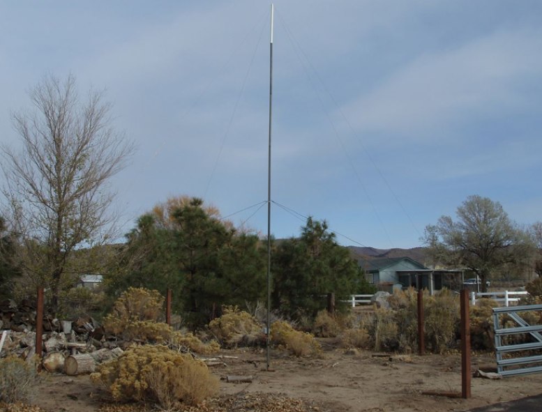 A K9AY loop antenna project done with Far Circuits pc boards for the antenna switch and bandpass filter and preamp by K7SFN
 -
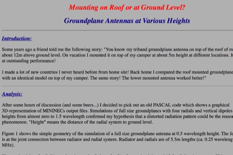 Mounting on Roof or at Ground Level? Why ground plane antenna works better at lower level.
 -
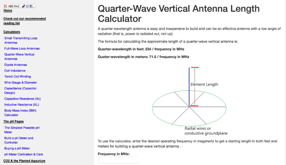 Use this online calculator to determine the length of a quarter-wave antenna from the frequency. Both metric and English units of measurement are supported.
 -
 Article by VU2GT about VHF antennas, how to evaluate performances and models.
 -
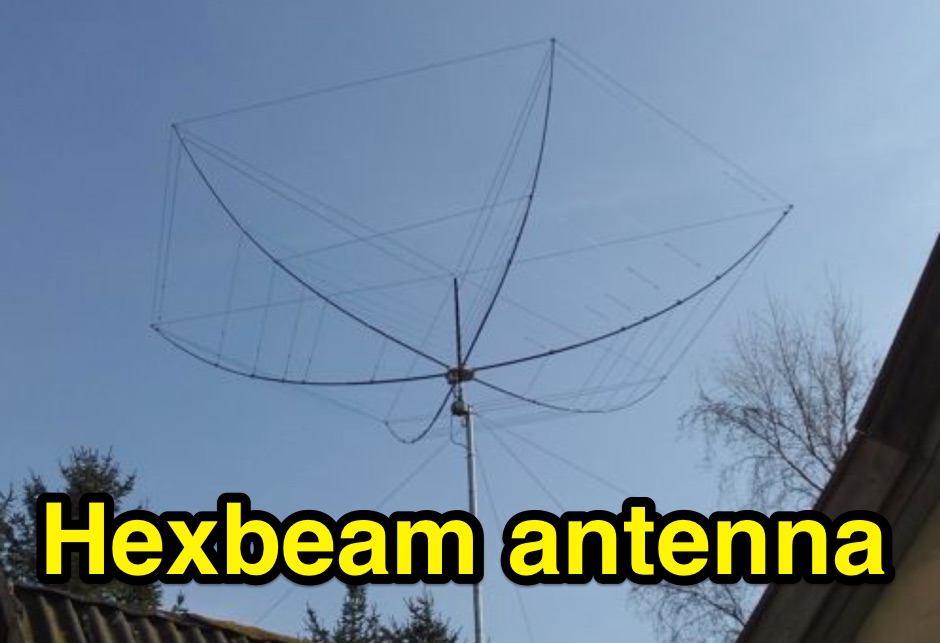 An HexBeam antenna project, a 2 full elements on six bands
 -
 The electrical characteristics of an antenna that are of interest to obtain by direct measurement are the frequency at which the antenna is tuned, the gain and radiation pattern
 -
 This resource details the construction of a portable antenna tripod designed for supporting small vertical antennas, utilizing readily available electrical metal tubing (EMT) or conduit. It outlines the necessary components, including a custom-fabricated _EARC tripod plate_, standard hardware, and a 10-foot section of 1/2-inch EMT cut into specific lengths for legs and a center support. The instructions cover assembly of the tripod plate, leg construction, and integration with a fiberglass fishing pole like the _Kwik Stix_ or _Shakespeare Wonderpole_ to support a vertical wire HF antenna. The project also describes an adaptation for using the tripod with 3/8x24 threaded mobile antennas such as _Hamsticks_ or _Buddisticks_, where the tripod structure itself contributes to the antenna's counterpoise system. A complete parts list is provided, along with ordering information for the specialized EARC tripod plate, which serves as a fundraiser for the Honolulu Emergency Amateur Radio Club. The document includes photos illustrating the assembled tripod and its use with a fiberglass pole.
 -
 This site serves a community of volunteer and paid professionals in Search & Rescue and Civil Air Patrol who save lives and Amateur Radio enthusiasts who use DF skills as a hobby. We provide antennas and other resources for people in these fields.
 -
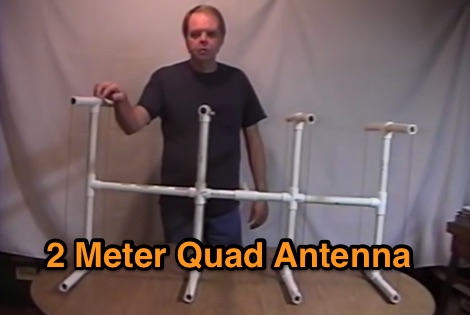 A four elements quad antenna for 144 MHz made with PVC pipes
 -
 General article on Baluns at myantennas.com, what is a balun and when to use baluns
 -
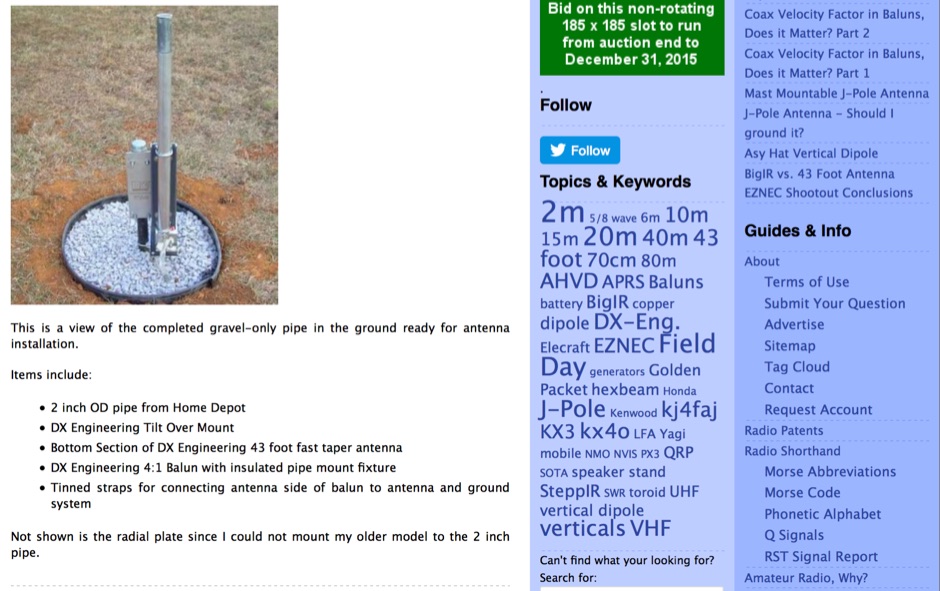 A step by step approach for a ham radio vertical antenna mount using only a hole, gravel and a piece of plumbing pipe
 -
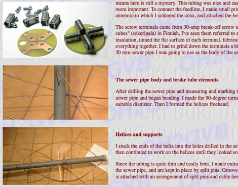 A page dedicated to the Quadrifilar Helical Antennas, with projects, pictures and antenna plans by OH2GVB
 -
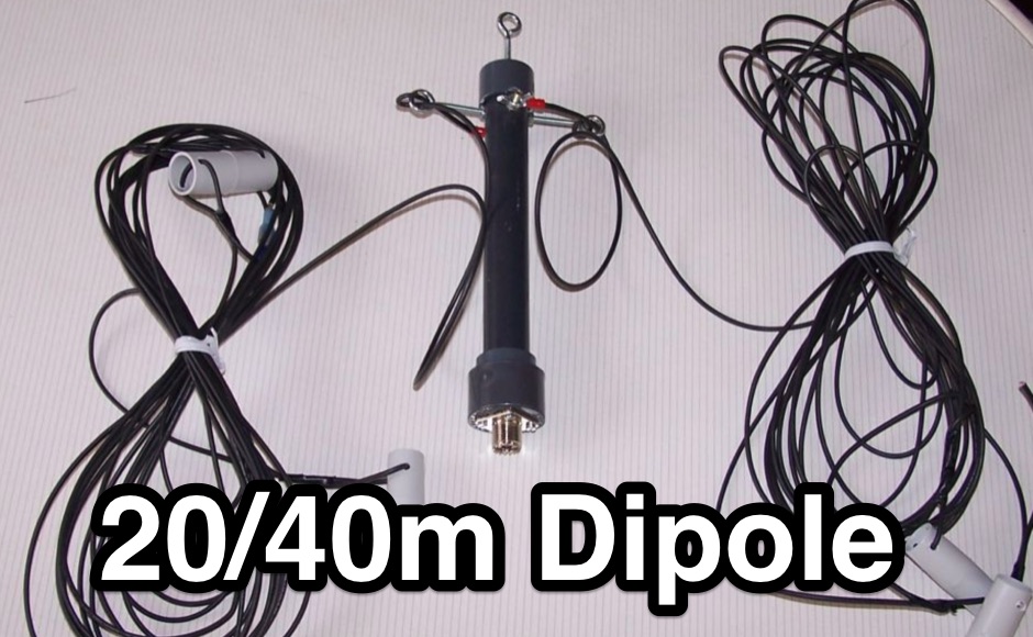 A simple to build full length 20/40 dipole antenna to be used in inverted vee configuration
 -
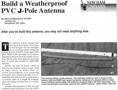 After you have build this antenna, you may not need anything else. This article shows how to build a VHF j-pole antenna and how to protect it by inserting it into a PVC tube, the correct way.
 -
 The collinear J-Pole, often known as the Super-J, does improve the behavior over a regular J-Pole. As many attest, there is an advantage when vertically combining 1/2 radiating sections to have a bit of separation between the half-wave end points. The Super-J has very little separation between the two half-wave radiators.
 -
 Demonstrates various practical amateur radio projects and technical discussions through video episodes. One episode details cutting and retuning a _1/4 wave shorted stub_ from 101.7 MHz to 107.5 MHz to safeguard a transmitter's driver stage, alongside insights into advanced _160-meter antenna systems_ like eight-circle arrays and beverage antennas. Another segment covers upgrading firmware on an _ATS-20+_ receiver using AverDudes for improved display and functionality, and a detailed guide on using D-Star DR mode on an _ICOM ID-52A_ for international repeater programming. Additional content includes a deep dive into _OpenHamClock_ as a potential replacement for the HamClock project, updates on _Raspberry Pi 5_ running Trixie OS, and a review of the Choyong LC90 Internet radio with AI integration. The series also features "Ham College" episodes, which meticulously prepare viewers for the Technician Exam by covering topics such as antenna and transmission line measurements, SWR interpretation, and the functions of basic electronic components like rectifiers, relays, and transistors. Practical advice on coaxial cable characteristics, dummy loads, and proper soldering techniques is also provided.
 -
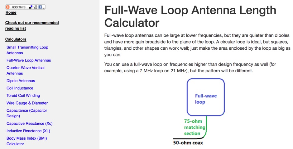 Use this online calculator to determine the length of a full-wave loop antenna from the frequency. Both metric and English units of measurement are supported. Quarter-wave matching section lengths are also calculated.
 -
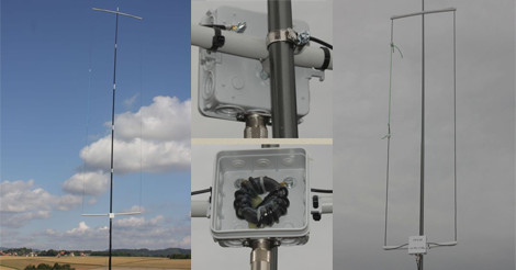 C-Poles for 20m and 6m, it is a folded half-wave dipole with an asymmetrical tapped 50-Ohm-point in the lower part of the antenna. Design hints by DK7ZB
 -
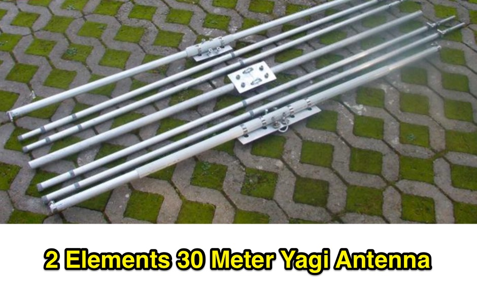 Dimensions and EZNEC plots for a 2 Element 30 meter Yagi antenna with 28 Ohm featuring 4.3 dBd Gain and a 16dB F/B with a good bandwidth.
 -
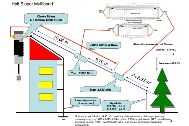 A presentation of a HF multi-band sloper antenna. This antenna project is for low band operations, and antenna presented in this article works on 40 80 and 160 meters band. Article is in Polish.
 -
 This page describes a cheap, weather-resistant and readily available type of antenna wire by HAMwaves.com
 -
 Modification of the Bill Petlowany, K6NO antenna by N0LX
 -
 VHF UHF half wave flower pot antenna project by VK2ZOI
 -
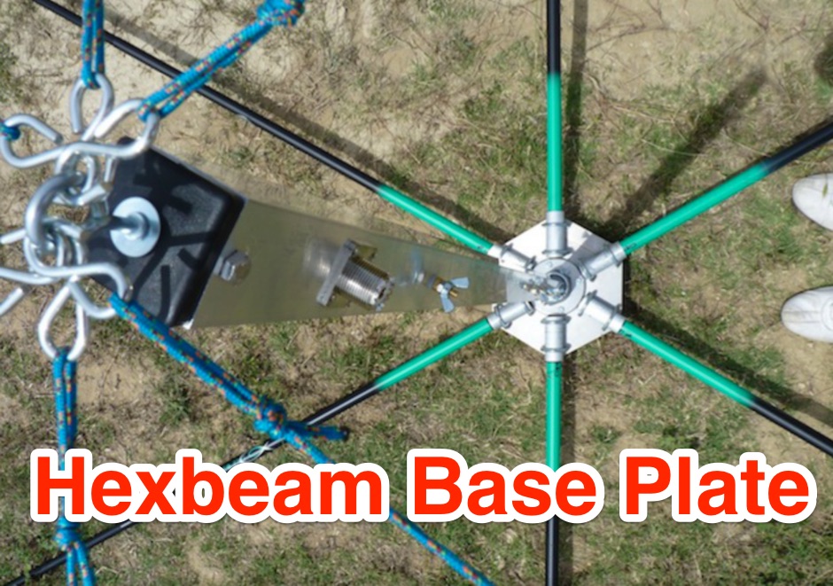 A 10mm thick aluminum plate serves as the foundation for a homemade hexbeam antenna, designed to support the central mast and six radiating elements. The construction details include precise drilling for the central mast and the six fiberglass spreaders, ensuring proper alignment and mechanical integrity. The author, FY8PE, shares insights from his experience, emphasizing the importance of robust materials for long-term outdoor deployment. The design incorporates a specific arrangement for the spreader attachment points, allowing for easy assembly and maintenance of the hexbeam's unique geometry. While specific performance measurements are not detailed, the focus on structural strength and material choice suggests an emphasis on reliability in various weather conditions. The project provides practical guidance for hams looking to build a durable hexbeam base.
 -
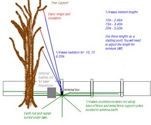 An indeal stealth antenna made by multiple quarter wave verticals, supported by a tree.
 -
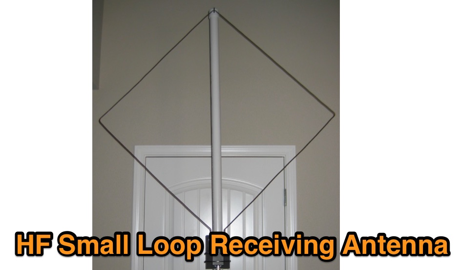 Receive-only loop antennas have some nice response characteristics that make them ideal when used for reception of skywave signals.
 -

-
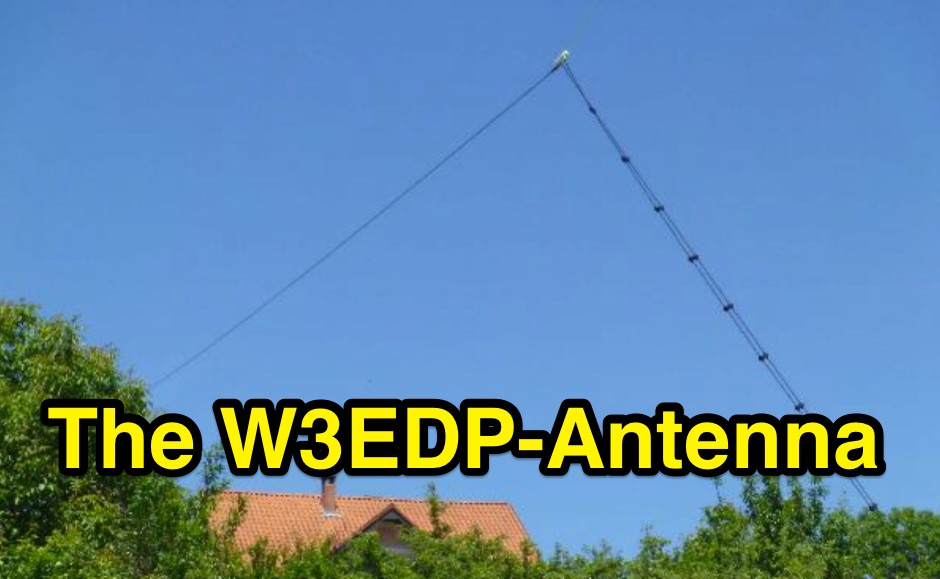 Hints for building a W3EDP-Antenna, includes the construction of the 1:4-balun by DK7ZB
 -
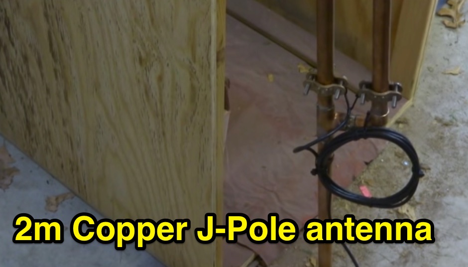 This is the construction of a copper cactus style j-pole antenna.
 -
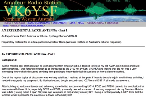 This web article by VK3BLG details the construction of an experimental 70cm (432 MHz) circularly polarized patch antenna, intended for satellite communication. The resource provides dimensions, feed point specifications, and impedance matching considerations for a single patch element, with discussion extending to array configurations for circular polarization. Construction involves a copper patch element on a dielectric substrate, fed via a coaxial cable. The design is based on information derived from AO-40 satellite antenna specifications, focusing on achieving circular polarization for satellite reception. The article includes specific dimensions for the patch and feed points, along with impedance values. Validation is implied through on-air satellite reception reports, with initial signal reports of **1 S-point above noise** for AO-40 beacons using a grid reflector, improving to **3-4 S-points above noise** with a 2-turn helical feed. The author references a _NanoVNA_ for impedance measurements and discusses the relationship between slot and dipole antennas in the context of patch design. DXZone Focus: Web Article | 70cm Patch Antenna | On-Air Satellite Reception | Circular Polarization
 -
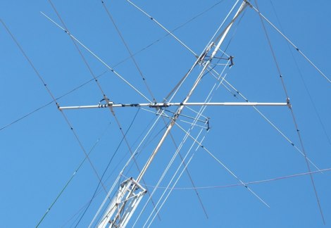 An homebrew project for a 4 elements yagi monoband antenna for the 10 meters by 9M2MSO
 -
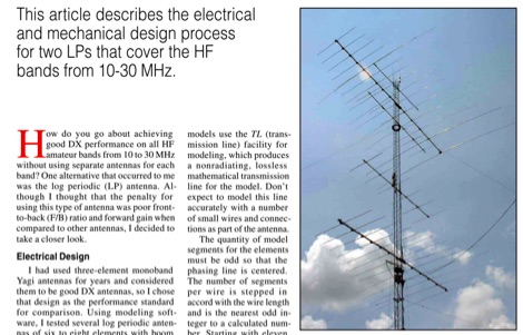 This QST article describes the electrical and mechanical design process for two LPs that cover the HF bands from 10-30 MHz
 -
 Homemade Jeep Tailgate Antenna Mount for use with a Swing Out Tire Carrier
 -
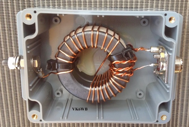 In this experiment the autor is going to explore the use of a 1:64 matching network on the End Fed Long Wire Antenna. Experiment will consist in build a 80-40-20-15-10 meter End Fed Long Wire Antenna with a 1:64 matching network from the documentation available on the internet
 -
 A motor tuned magnetic loop antenna that can work from 14 MHz to 30 MHz
 -
 A multiband coax trapped dipole for 10-80 meters bands by DF1PU
 -
 Understanding Amateur Radio NVIS Antennas and Propagation, derived from The ARRL Antenna Book and QST Articles
 -
 Examining the _Angle of Radiation_ and its impact on amateur radio operations, the resource provides insights into optimizing antenna performance for DX and local contacts. It features a design for SPOTTO, a direct conversion high-performance universal DSB transceiver, detailing its construction and operational characteristics for homebrew enthusiasts. Additionally, the site presents a 7-element VHF high-gain antenna design, offering practical schematics and expected performance metrics for those seeking enhanced gain on VHF bands. The resource also covers the development and popularity of the _FT8_ digital mode, highlighting its effectiveness in weak-signal conditions and its role in special event operations like the FT8DMC anniversary. It includes information on Hamfest India 2023 and the Lamakaan Amateur Radio Convention, providing dates and organizational details for significant Indian amateur radio gatherings. Technical articles on Direct Digital Synthesizers (DDS) VFOs and low-cost multifunctional frequency counters offer practical project ideas for radio amateurs.