Search results
Query: 11 antenna
Links: 190 | Categories: 0
-
 Green that aluminum into something useful right in your own backyard by WB2CQM
 -
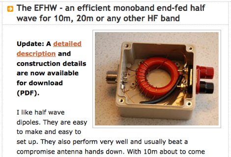 An efficient monoband end-fed half wave for 10m, 20m or any other HF band
 -
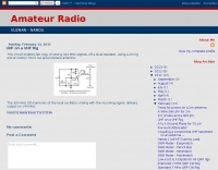
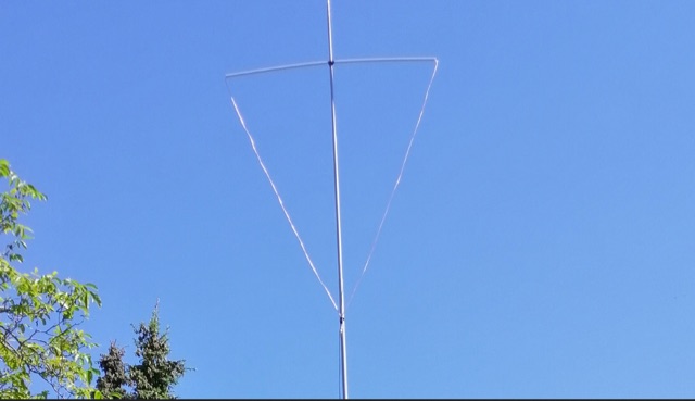
 This PDF document details the construction of a **70 MHz** Big Wheel antenna, a horizontally polarized omnidirectional array. The design utilizes three full-wave loops, each approximately **2160 mm** in diameter, arranged in a triangular configuration. The resource provides mechanical dimensions for the antenna elements and a comprehensive bill of materials, specifying component quantities and types, such as M8 stainless steel bolts, 15x15x1.5 mm square aluminum tubing for spacers, and 8 mm aluminum rod for the arcs. The central hub is constructed from two 160x160x8 mm aluminum plates, with four 40 mm long polyamide insulators supporting the radiating elements. The feed system incorporates a 50 mm diameter aluminum pipe for mounting and a matching stub constructed from a 120x20x2 mm aluminum sheet, connected via M8x10 mm bolts. The resource includes a diagram illustrating the mechanical dimensions and assembly points, including the N-connector fixing point and the center conductor attachment. The project was published on May 25, 2011, by Peter OE5MPL and Rudi OE5VRL. DXZone Focus: PDF | 70 MHz Big Wheel | Mechanical Dimensions | **2160 mm** loop diameter
 -
 A three band short Vee antenna is feasible with two legs per side on a dipole. 10-15-20 meters by W8HDU
 -
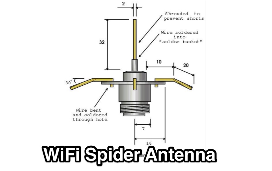 Quarter wave omni-directional spider antenna for 2.4GHz 802.11b
 -
 This project produces a sturdy tripod for small vertical antenna support using readily available electrical metal tubing (EMT) or conduit
 -
-
 Antenna for limited space, made from 24AWG wire helically wrapped around the top element of a 3-element cane pole, is basically a fully-loaded vertical and performance are limited and should represent the last resort for extreme cases.
 -
 This is a one for all antenna tuner with wide range tuning on all the HF bands. The tuner is based on a G3WQW design. DIY project by PD7MAA
 -
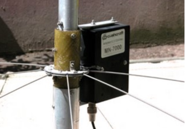
 Antenna tuners are crucial for matching the impedance of antennas to the 50 ohm output impedance of transmitters. The _LDG Z-11 Pro_ is an automatic antenna tuner designed to handle up to 125 watts, making it suitable for a wide range of amateur radio applications. Its compact form factor allows it to pair well with transceivers like the _FT-857D_, providing a portable solution for operators who frequently change locations or setups. The tuner covers the 80 through 6 meter bands, offering a broad impedance match capability. Although it struggles with some loads, it performs well with typical ham antennas, even managing to load an 80 meter dipole on 6 meters. One of the standout features of the _Z-11 Pro_ is its 8000 memory slots, which enable it to remember successful matches and quickly retune when revisiting frequencies. This memory function significantly reduces tuning time, often to less than half a second. The unit is well-constructed, with improved pushbuttons and a sturdy metal case that offers good shielding. However, users should be aware of potential RFI issues and the lack of a power switch, which requires disconnecting the power cord to turn off the unit completely. Overall, the _LDG Z-11 Pro_ is a user-friendly and cost-effective tuner, offering advanced features that enhance its utility in various amateur radio setups.
 -
 Cushcraft A3S HF antenna 1:1 balun repair.
 -
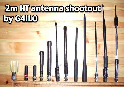 G4ILO compares popular antennas for 2 metre band handhelds so as to see how much you lose using a small inconspicuous antenna or how much you gain by using a long antenna.
 -
 This circuit enables fair copy of strong 444 MHz signals, off a local repeater, using a 2m rig and a 1/4λ 70 cm indoor ground plane antenna.
 -
 A 200 kHz bandwidth digital transmission system for image transfer in the Amateur Service is under development, specifically targeting VHF allocations. John B. Stephensen, KD6OZH, leads this project under an FCC Special Temporary Authority (STA) valid until September 10, 2006, authorizing emissions up to 200 kHz bandwidth in the 50.3-50.8 MHz segment. Current regulations typically limit bandwidths to 20 kHz on VHF amateur bands, making this STA crucial for testing wideband digital modes. The modem, a modified **OFDM** (Orthogonal Frequency Division Multiplexed) unit, was initially tested on the 70-cm band. It splits a high-rate data stream into multiple low-rate subcarriers to mitigate multipath echoes. The system uses a DCP-1 card with a Xilinx XC3S400 FPGA and Oki Semiconductor ML67Q5003 microcontroller. The transmitter, located at 36d 46m 30s N, 119d 46m 22s W, generates 150 WPEP into an 8 dBi gain vertical antenna, while the mobile receiver uses a Ham-stick. Three data formats for 50, 100, and 200 kHz channels are being tested, with encoded data rates of 96, 192, and 384 kbps. Verilog code for the VHF OFDM modem is 95% simulated, with modifications from the UHF version including increased filter coefficient precision and a change from Ungerboeck **TCM** to BICM for improved performance over fading paths. Final tests will involve one-way over-the-air measurements of bit error rates and coverage area.
 -
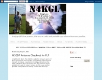 The W3EDP is a 85 foot long wire and a 17 foot counterpoise. At N4KGL
 -
 An homebrew project of a full wave delta loop antenna for the 40 meters band with dimensione, picture and assembling instructions in Indonesian
 -
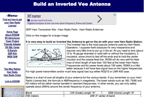 Notes on how to build an inverted V wire antenna with lenghts for all HF bands from 160 mtrs to 10 mtrs
 -
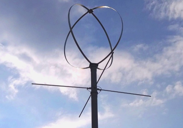
 KD8KSB realization of the CJU satellite antenna that allow similar performance to the arrow antennas.
 -
 A no ground antenna solution for backpackers, balconies or plastic car bodies, like RV or other portables uses where is difficult to find a good counterpoise by PD7MAA
 -
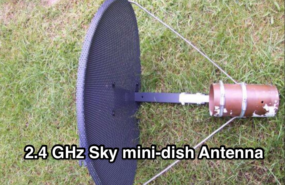 How to modify a Sky mini-dish so it will work effectivly at 2.4Ghz.
 -
 Demonstrating the construction of a short dipole antenna tailored for the 60 meter band, this resource provides detailed instructions for radio enthusiasts with limited space. The design incorporates inductive loading using two inductors (L1/L2) made from PVC tubes, allowing for effective operation on 5 MHz. The antenna consists of 12 meters of wire, divided into four sections, with specific dimensions and materials outlined for optimal performance. Results from users indicate that this antenna can significantly enhance DXing capabilities on the 60 meter band. Feedback from operators suggests that while the design is effective, adjustments may be necessary based on individual setups, such as coil diameter and wire gauge. Many users report successful construction and operation, with some experimenting with variations to improve resonance. The practical application of this antenna design has led to successful contacts and improved signal quality, making it a popular choice among 60 meter band operators.
 -
 The **Solarcon A99** vertical antenna, a half-wave over a quarter-wave variable mutual inductance design, primarily serves the 11-meter CB band but also finds use on 10 and 12 meters for amateur radio operators. Its simple construction, consisting of three fiberglass sections and a 16 AWG radiating element, makes it an accessible option for new operators or those seeking an easy-to-install base station antenna without complex mounting requirements. Despite claims of 9.9 dBi gain being widely considered exaggerated, and a manufacturer rating of 2000 watts power handling often viewed with skepticism (with 300 watts suggested as a practical limit), the A99 maintains popularity due to its low cost and ease of deployment. It typically tunes to a 1.2-1.3 SWR out of the box, requiring minimal adjustment via its two tuning rings. Its high angle of radiation allows for effective local communication even when mounted at low heights, such as 8-10 feet off the ground. However, the A99 is known for significant RF bleed-over issues, particularly when operated with higher power or mounted close to residential electronics. While its internal design is often described as cheap, the antenna exhibits remarkable durability, frequently lasting a decade or more in various weather conditions. Its affordability and straightforward setup continue to make it a go-to choice for many radio enthusiasts.
 -
 An economical dipole for simple QRP HF homebrew rigs
 -
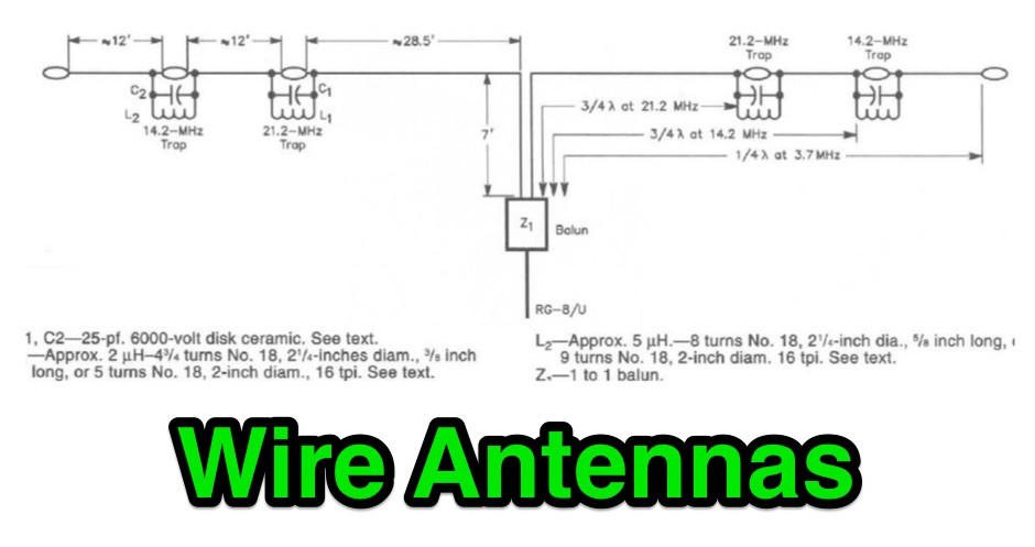 A collection of drawings of most popular wire antennas for hf ham radio bands
 -
 A handy solution to have a half wave antenna for fieldwork on a 12m fishing rod.
 -
 137 kHz propagation analysis details ground wave and sky wave mechanisms, drawing heavily from **CCIR Rec. 368-6** for ground wave field strength predictions and **CCIR Rep. 265-7** for sky wave modeling. The resource presents field strength values for 1 W ERP at varying distances, considering ground conductivity and permittivity for ground wave, and ionospheric height (70km daytime, 90km nighttime) for sky wave. Key factors like ionospheric focusing (factor "D"), reflection coefficient ("RC"), and antenna ground pattern factors ("Ft", "Fr") are quantified for 137 kHz, enabling calculation of sky wave field strength. Practical coverage ranges are derived for 137 kHz, showing useful ground wave coverage up to 1600 km over seawater and 1100 km over average ground, assuming a -9 dBuV/m noise floor. Sky wave coverage extends beyond 2200 km during night-time and winter daytime, but is negligible during summer daytime at solar minimum. The document also compares ground wave and sky wave strengths, identifying crossover distances at 550 km (night-time), 750 km (winter daytime), and 1250 km (summer daytime), where interference fading can occur. Adjustments for solar maximum conditions are provided, indicating 2-11 dB higher sky wave values depending on distance and season.
 -
 T2FD is a 600-900 ohms folded dipole, terminated with resistor. Feed impedance is coupled with 50/600 ohms voltage balun. It is a wide band antenna with rather low SWR over the full designed frequency range: antenna tuner is seldom needed.
 -

-
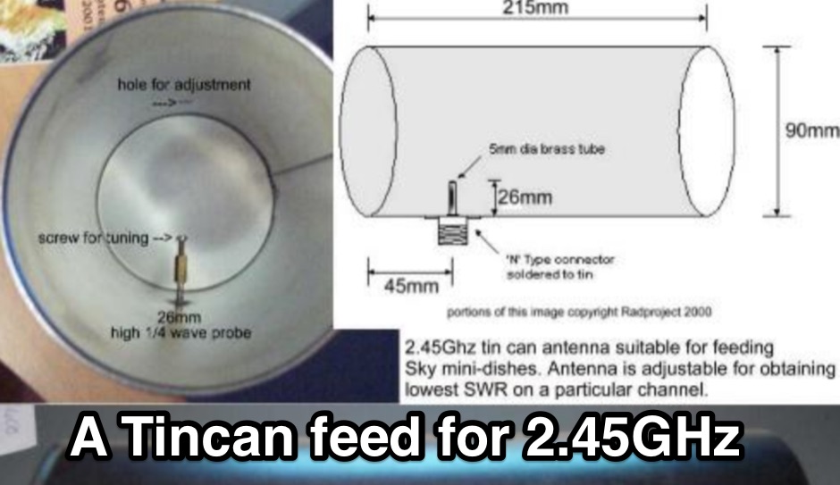 Construction details for a simple but effective antenna for 2.45Ghz wireless lan use.
 -
 A moxon antenna for the 50 MHz build with 19 feet of 14 AWG copper wire, and based on a set of PVC pipes. This is an easy to build project that will give you an efficient directional antenna on 6 meters band with low SWR on more than 1 MHz bandwidth.
 -
 How to setup a proper antenna feed line with a particular attention to RFI by K0GKJ
 -
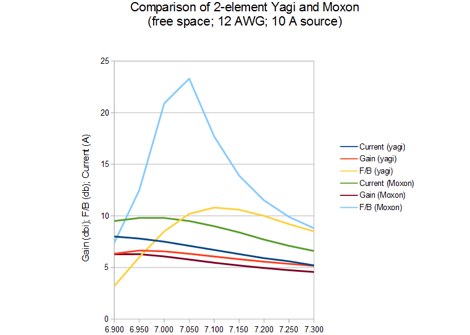 An interesting article by V2EVN on moxon yagi antennas
 -
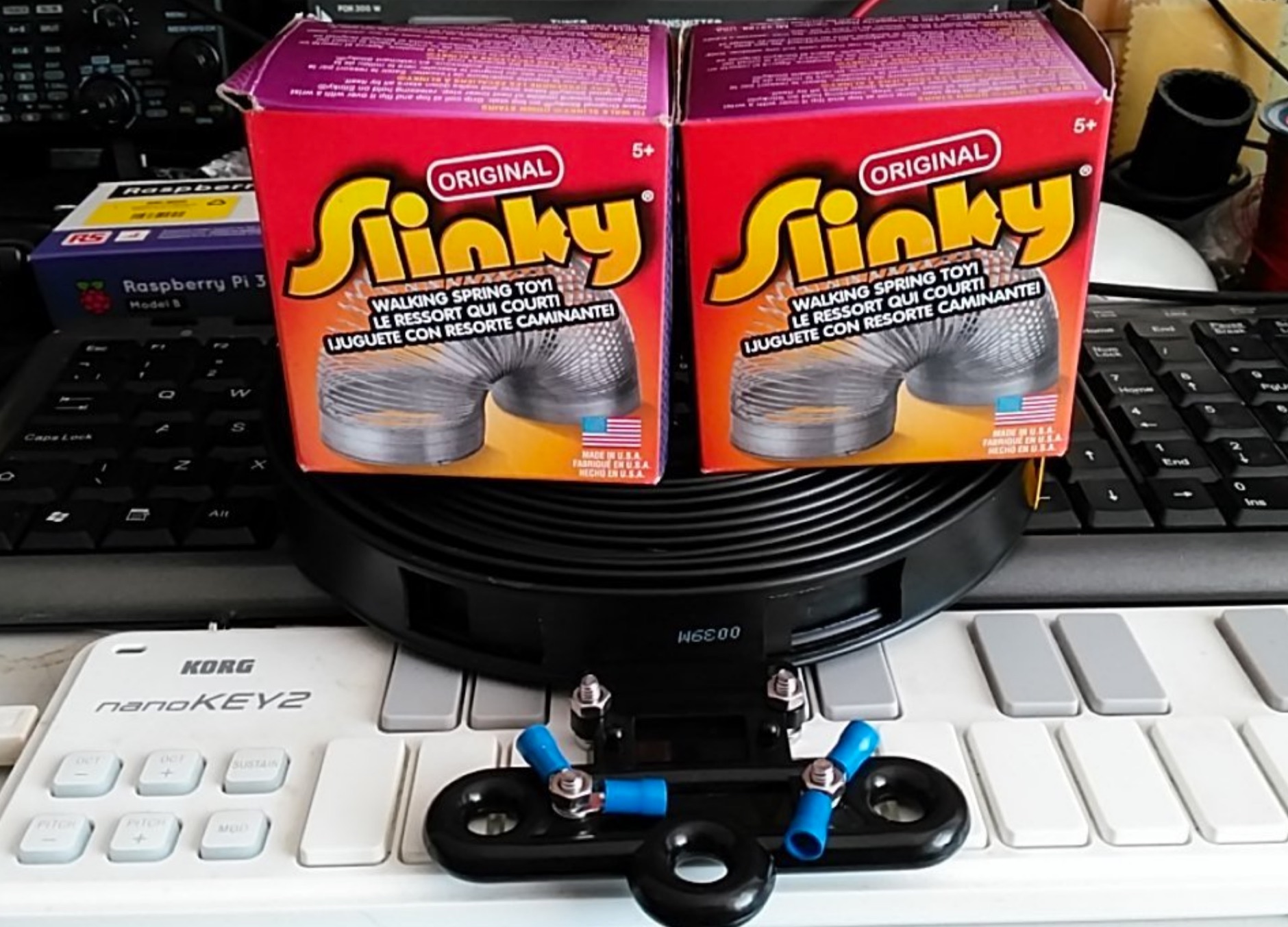 An home made doblet antenna made with two Slinkys that are aproximately five meters in length connected with a twin-feed connected to a balanced ATU
 -
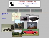 Antenna Authority Inc. offers a wide assortment of directional, wideband antennas and other equipment specifically engineered for radio direction finding (DFing) and geolocation applications. Their product line includes _log periodic_, _cavity-backed spirals_, and _Yagi_ antennas, alongside covert antenna solutions for various operational requirements. The company emphasizes its expertise in designing and manufacturing specialized antennas for both overt and covert operations. Beyond standard offerings, Antenna Authority Inc. provides custom design services to meet specific client needs, focusing on tailored RF directional products. Their capabilities extend to developing antennas for vehicles and optimizing their operational performance in diverse scenarios. The firm is located at 3381 W. County Line Road, Douglasville, Ga. 30135-1145. Ferrel Bentley is associated with Antenna Authority Inc., which has been operating since at least 2005, as indicated by the copyright notice.
 -
 A dual band dipole antenna for 40 and 80 meters band. Total lenght of 26 meters, foreseen two coils at aprox 11 meters distance from center feed.
 -
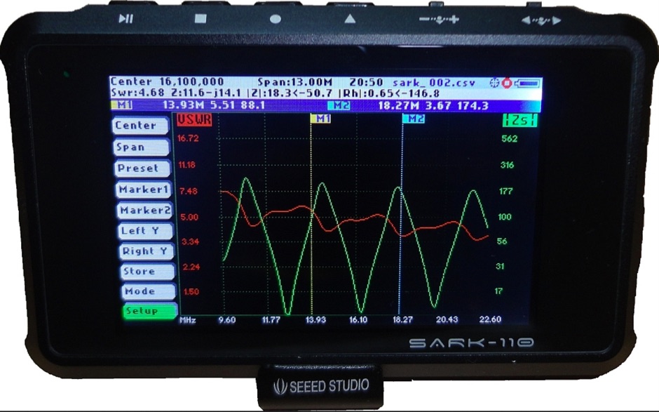 The SARK-110 is a completely new design concept for an Antenna Analyzer. This is a truly pocket size device, so you can take it anywhere. It offers a gorgeous 3" high-resolution, active-matrix color display that allows information-rich diagrams, works from 0.1 to 230MHz
 -
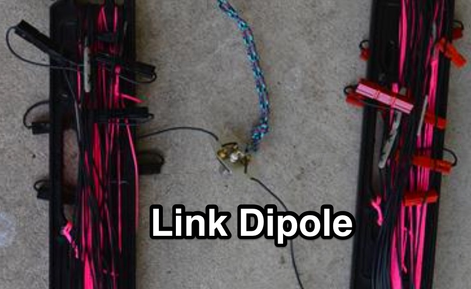 Homebrewing a Lightweight linked dipole HF antenna for portable SOTA operations
 -
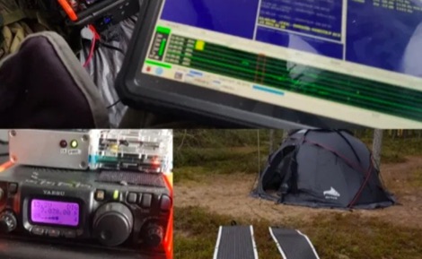 Operating a QRP station in frigid conditions presents unique challenges, particularly concerning power management and equipment reliability. This resource outlines a specific winter portable configuration, focusing on maintaining operational capability when temperatures drop significantly. It details the use of a _Yaesu FT-817ND_ for digital QRP modes, paired with a _Raspberry Pi_ for digital signal processing and logging, demonstrating a practical approach to cold-weather field communications. The article provides insights into selecting appropriate power sources, such as LiFePO4 batteries, and managing their performance in sub-zero environments. It also covers shelter considerations, including tent selection and heating strategies, crucial for operator comfort and equipment protection during extended activations. The author, _OH8STN_, shares firsthand experience from Arctic Circle operations, emphasizing robust gear choices. Further content includes a video walkthrough, illustrating the physical setup of the station, antenna deployment, and the overall operational workflow in a winterized environment. This visual aid complements the written text, offering a comprehensive view of the entire portable station, from the transceiver to the power system and the protective shelter.
 -
 Presents _Beam Quest_, the official Japanese distributor for _SteppIR_ antennas, detailing their product lineup and services. The site showcases various _SteppIR_ Yagi models, including the _Dream Beam_ series (DB42, DB36, DB18E, DB11) with configurations from two to four elements, alongside the _Big IR_ and _Small IR_ vertical antennas. It also lists accessories such as TX/RX and PC interfaces, essential for integrating these advanced antenna systems into a ham shack. Operators often seek out _SteppIR_ antennas for their dynamically adjustable element lengths, which allow for optimization across multiple bands, a significant advantage for DXing and contesting. This adaptability contrasts sharply with fixed-element Yagis, providing a distinct edge in varying band conditions. The resource provides contact information, including email and phone numbers, for inquiries and support regarding _SteppIR_ products within Japan, serving as a direct point of contact for sales and technical assistance.
 -
 A modified Hairpin antenna for a wider bandwidth an mounted on a grounded metalic mast
 -
 The ZS1J/B beacon operates on 28.2025 MHz with 5 Watts output to a half-wave, end-fed vertical antenna, initially installed in 1977 as ZS5VHF near Durban. The 10-meter transmitter is a modified 23-channel CB radio, and the identification keyer uses a diode matrix unit with TTL ICs from the same era. After relocation to Plettenberg Bay in 1993, the beacon has been in continuous service, with additional QRP transmitters later installed for other bands. In 1994, a single-transistor, 80-meter, 0.5-watt QRP transmitter with a half-wave dipole was added on 3586 kHz, followed by a 160-meter, 0.5-watt unit on 1817 kHz. A 30-meter, 0.5-watt transmitter was installed in 1996, operating on 10.124 MHz. In 2002, a 40-meter QRRP beacon on 7029 kHz, with an output of 100 microwatts, achieved DX reports up to 1100 km from ZS6UT in Pretoria. Best DX reports for the 80m and 160m beacons came from 9J2BO.
 -
 This is a antenna tuner with wide range tuning for antennas with a Z of + 50 Ohms on all the HF bands.
 -
 KC901S Handheld vector antenna analyzer RF ANALYZER 3GHz S11 S21 Fieldmeter RF Source Spectrum
 -
 Repairing a Cushcraft R7000 antenna featuring several problems, mostly concerning coils and the insulating parts of the antenna.
 -
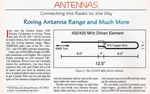 A 18 elements Yagi antenna for 432/435 MHz as published on 2011 CQ VHF magazine
 -
 A homemade delta loop antenna for six meters band in German
 -
 High Speed Multimedia (HSMM) radio, as introduced by John Champa, K8OCL, represents a significant advancement in amateur radio's digital capabilities, moving beyond traditional keyboard modes like packet radio. This initiative, driven by ARRL's Technology Task Force, focuses on developing high-speed digital radio networks capable of up to 20 megabits per second. HSMM primarily facilitates digital voice (DV) and digital video (ADV), enabling real-time video transmission from emergency scenes to an EOC without expensive ATV gear, often requiring only a laptop, a PCMCIA card, a digital camera, and a small antenna. The working group's initial efforts concentrate on cultivating microwave skills within the amateur community to build and support portable and fixed high-speed radio-based local networking, or **RLANs**. These networks prove invaluable for RACES and ARES organizations, as well as homeland security and other emergency communications. Field Day exercises and simulated emergency tests (SETs) are encouraged to hone skills in rapid site surveys and deploying broadband HSMM microwave radio networks, with examples like linking Field Day logging stations or antenna test results at the Midwest VHF-UHF Society Picnic 2003. Getting started with HSMM often involves adapting off-the-shelf **IEEE 802.11** (WiFi) equipment to comply with amateur radio regulations, typically operating in the 2.4 GHz ISM bands. While consumer WiFi gear has range limitations under Part 15 rules, proper setup under amateur regulations can extend coverage significantly, with test networks like the Hinternet achieving 5-15 mile ranges at 54 M bit/s using small mast-mounted dish antennas. Careful selection of equipment with external antenna ports, high transmit power, and low receive sensitivity is crucial, along with using low-loss coaxial cable like LMR-400 for optimal performance at these frequencies.
 -
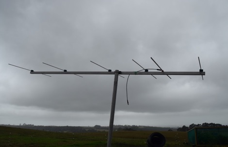 YU7EF EF0206 2m Band 6 Element Yagi Antenna project, provides 11.8 dbi gain
 -
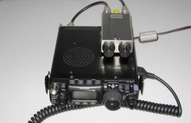
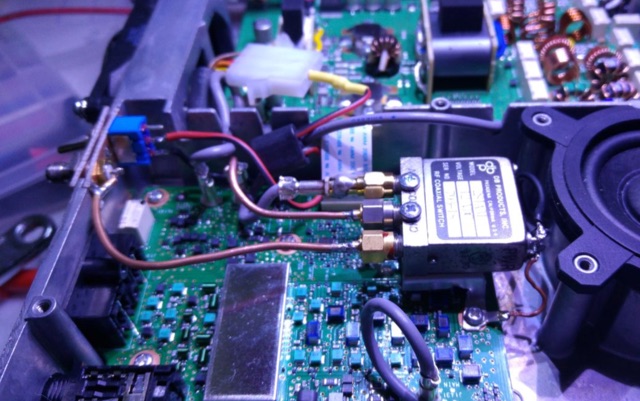 Despite the model limitations, such as a single TXRX antenna connector, the author shares a reversible modification involving a coax relay for enhanced functionality, demonstrating the transceiver's adaptability and customization potential.
 -
 With this antenna the coverage is 80,40,20,15 and 10 meter band without any antenna tuner and the average SWR is below 1.2 on phone bands. The total antenna lenght is about 23 meters , with one 20.4 meters long segment from the 1:49 transformer to the 110uh coil and about 2.2 meters long segment from the coil to the insulator.