Search results
Query: space
Links: 308 | Categories: 4
-
 A 20-meter vertical _Moxon_ antenna, designed for portable operation, is detailed with specific dimensions for its driven and reflector elements. The project outlines the construction process, including the use of PVC pipe for the frame and #14 AWG insulated wire for the elements. The antenna's compact size and directional characteristics make it suitable for field day operations or limited space environments, offering a gain of approximately 5.5 dBi and a front-to-back ratio of 20 dB. Testing revealed a 1.2:1 SWR at 14.250 MHz, demonstrating good impedance matching across the target frequency range. The _Moxon rectangle_ design provides a clean radiation pattern with minimal side lobes, which is advantageous for reducing QRM from unwanted directions. This build offers a practical solution for hams seeking a lightweight, easily deployable directional antenna for 20 meters without the complexity of a full-sized Yagi.
 -
 Ballistic simulator "Orbit" allows the physical principles of the motion in the gravitational field of the Earth to be demonstrated and learned. You can calculate with this program the ballistic trajectories of the thrown bodies and orbits of spacecrafts and visualize the astroballistic situation on the flat map of the world and on the rotating globe in the real time
 -
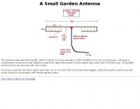 This antenna was described by Bill, G4KIH in Sprat 52 and is actually a G5RV modified to fit into a small space.
 -
 The ZS6BKW antenna, a popular multiband wire antenna, offers improved band matching compared to the traditional G5RV. This construction guide details the process, beginning with specific dimensions: 13.11 meters (43 feet) for the 450-ohm ladder line and initial dipole arm lengths of approximately 14.8 meters each. It emphasizes the critical role of an _antenna analyzer_ for accurate tuning, particularly for determining the velocity factor of the ladder line and achieving a 1:1 impedance match. The article outlines the materials required, including a 1:1 current balun, 450-ohm window line, wire for the dipole arms, and a 50-ohm non-inductive resistor for testing. It provides a step-by-step procedure for cutting the ladder line to its electrical half-wavelength, explaining how to calculate the velocity factor using measured and free-space frequencies. For instance, a measured 50-ohm impedance at 12.54 MHz with a calculated free-space half-wavelength frequency of 11.44 MHz yields a velocity factor of 0.91. Final adjustments involve hoisting the antenna to its operational height and fine-tuning the dipole arm lengths to achieve optimal SWR, specifically targeting 14.200 MHz. The _ZS6BKW_ design is noted for its performance on 80m, 40m, 20m, 10m, and 6m, though it is not optimized for 15m operation. The author, _VK4MDX_, shares practical tips for durable construction using stainless steel wire and cable clamps.
 -
 An Attic version for limited space applications by NW9T
 -
 This program has been designed for packet communication with ISS (International Space Station), PCSat or 'compatible' satellites with ease... Ideal for any UI packet communication.
 -

-
 A 2m Moxon antenna project, designed for the 145 MHz amateur radio band, provides a compact, directional solution for VHF communications. This resource details the construction process, specifying materials like PVC pipe for the frame, copper wire for elements, and a SO-239 connector for the feedpoint. The design emphasizes ease of build for hams seeking a gain antenna with good front-to-back ratio for local ragchewing or contesting. The project outlines precise element lengths and spacing, crucial for achieving the desired impedance and radiation pattern. It includes a visual representation of the antenna's dimensions and assembly, allowing for straightforward replication. The Moxon's inherent characteristics offer a practical alternative to larger Yagi arrays, particularly for portable operations or restricted spaces, while still delivering effective directivity and gain.
 -
 This QRZ.com callbook entry by DL6GD details the construction and performance of a **40m/80m Morgain folded dipole antenna**. The resource includes a schematic diagram, construction photos, and tuning notes. The antenna, with a total length of **20.30m**, was mounted at a height varying from 4m to 6m above ground. Construction utilizes 0.75 sq mm transparent insulated copper wire, with Plexiglas spreaders (5mm thick, 70x10mm) spaced at 25mm intervals, secured with hot glue. A waterproof junction box houses the feedpoint and balun. Tuning involved adjusting wire bridges for resonance on each band. On 80m, an SWR of **1.1:1** was achieved at 3.657 MHz, with an SWR of 2.7:1 at 3.580 MHz and 2.5:1 at 3.755 MHz, yielding a bandwidth of 175 KHz. For 40m, an SWR of **1.1:1** was measured at 7.100 MHz, with 1.5:1 at 7.000 MHz and 1.3:1 at 7.200 MHz, providing a 200 KHz bandwidth. DL6GD notes that 80m tuning exhibits slight height sensitivity, while 40m tuning is less affected by height or 80m adjustments. Long-term observations from 2014 and 2022 document SWR degradation due to environmental factors like spiderwebs and ice accumulation, which can cause HF-conductive paths between elements. DXZone Focus: Callbook Entry | 40m/80m Morgain Dipole | SWR Measurements | 20.30m Length
 -
 Announce your callsign at least once every ten minutes. HamTime runs in the corner of the screen and gives you an audible alarm when that announcement is due.
 -
 Demonstrates the design principles and performance characteristics of **corner reflector antennas**, emphasizing their high gain and directional properties. It covers critical design factors such as the corner angle and the spacing between the radiating dipole and the reflector vertex. The resource explains how reducing the corner angle increases gain but lowers feed impedance, making matching more challenging. Practical angles of 90 degrees or 60 degrees are discussed, with 90 degrees offering easier impedance matching despite slightly lower gain. Details key design considerations, including reflector side length exceeding two wavelengths and reflector width greater than one wavelength for a half-wave radiator. It specifies reflector construction using wire netting, sheet metal, or parallel metal spines spaced less than 0.1 wavelength. The article provides a table with general dimensions for UHF and VHF bands, noting typical impedance values of 50 to 75 ohms and expected SWR of 1.7:1 on the lower band edge. Adjustable radiator-to-vertex spacing is highlighted as crucial for final tuning.
 -
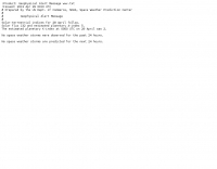 Broadcast via WWV and WWVH at 18 and 45 minutes past the hour. This message is updated every 3 hours. Reports current Solar-terrestrial indinces, Solar Flux, A-index, K-Index, forecast for space weather storms. Prepared by the US Dept. of Commerce, NOAA, Space Environment Center
 -
 How to operate on 10 and 20 meters in limited space with this trapped dipole.
 -
 This online article provides a list of individuals who hold or have held amateur radio callsigns, detailing their public recognition. The resource identifies specific callsigns such as **K1JT** (Joe Taylor, Nobel Prize in Physics), **W6OBB** (Art Bell, syndicated radio personality), and **JY1** (King Hussein of Jordan), linking them to their non-amateur achievements. It also notes operational statuses like _Silent Key_ for deceased operators and _lapsed callsign_ for inactive licenses. The article includes information on callsign changes due to vanity callsign programs and provides examples of individuals involved in specific technical areas, such as Percy L. Spencer (**W1GBE**), inventor of the microwave oven, and Jay Kolinsky (**NE2Q**), inventor of electronic sirens. It also references amateur radio involvement in _space missions_ for individuals like Owen Garriot (**W5LFL**) and Helen Sharman (**GB1MIR**). DXZone Focus: Online Article | Famous Hams | Callsign Status | Vanity Callsigns
 -
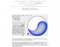 SimSmith is a highly interactive, real time Smith chart graphing program. Circuits are constructed using drag-n-drop. Load files can be imported from the EZNEC and CocoaNEC antenna simulation software and from the AIM4170 and miniVNApro antenna analyzers. Circuits and load files can be of any size. Key Features: SimSmith is one of the few Smith chart packages which models transmission line losses. SimSmith also allows the description of circuit elements using algebraic equations. SimSmith has only one screen and allows the screen to be resized to increase workspace or readability.
 -
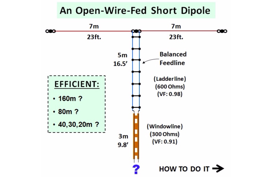 A shortened 160 meters band antenna for hams who do not have 260 ft of space, based on a open-wire-fed short dipoole
 -
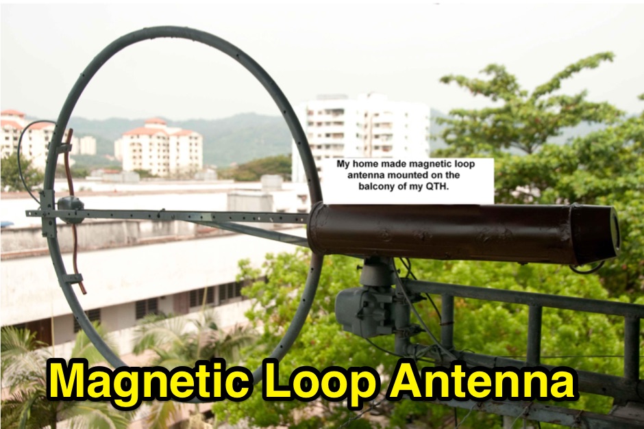 If you have space constraint at your QTH for a HF antenna, you can try contructing this HF magnetic loop antenna for 40-20 meters bands
 -

-
 DX_Central, a compact desktop application, provides amateur radio operators with critical propagation data by aggregating solar statistics and imagery from various authoritative sources. This includes real-time information from agencies like NOAA and NIST, offering insights into current space weather conditions that directly impact HF propagation. The software is designed for both Linux and Windows operating systems, making it accessible to a broad range of hams. It presents a concise overview of solar activity, which is essential for planning DX operations and understanding band openings and closures across the HF spectrum. Operators can utilize the displayed solar flux index, K-index, and other relevant parameters to make informed decisions regarding their operating times and target bands, optimizing their chances for successful long-distance contacts.
 -
 A 4 elements handitenna for 70 cm band. This is my version of the K5OE Handitenna. This one is a four Element instead of three, as I had less of a crunch on space than he did. The 1st three elements (Reflector, Driven Element, and Director 1) are the same dimensions as his were.
 -
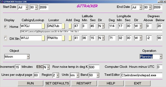 GJTracker is a antenna tracking program for windows written to be compatible with WSJT
 -
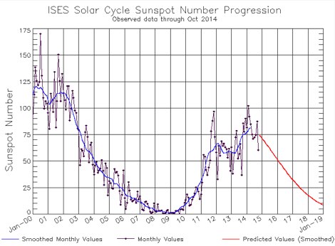 The charts on this page depict the progression of the Solar Cycle. The charts and tables are updated by the Space Weather Prediction Center monthly using the latest ISES predictions
 -
 A compact antenna for 160 meters, suitable for hams tha want operate top band buh have a limited space
 -
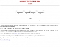 This short dipole antenna has been described by Nadisha, 4S7NR and may be of interest to anyone wishing to get on 80M (3.5MHz) that have limited space available.
 -
 How Vacuum Tubes Really Work. Vacuum tubes rely on hot cathodes emitting electrons and a plate attracting them to create current. A grid in between controls the current flow, enabling amplification. This article explores the nitty-gritty of how it works, including how cathode type, temperature, and electrode spacing affect the process. It explains the physics behind electron emission, space charge, and amplification factor, offering a deeper understanding than the basic principles.
 -
 The resource details the construction of a 3-element Yagi antenna specifically designed for the 6-meter band, providing coverage across 50-54 MHz. This antenna design, originally featured in _QST_ August 2007, emphasizes a short boom configuration while maintaining a wideband response. Key specifications include a 50 Ohm SWR of less than 2:1 across the entire band, achieved through specific element lengths and spacing. The design utilizes aluminum tubing for elements and boom, with detailed dimensions provided for the driven element, director, and reflector. Performance characteristics indicate a forward gain of approximately 7.5 dBi and a front-to-back ratio of 18 dB at 50.125 MHz, according to _NEC2_ modeling. The antenna's compact size, with a boom length of 1.83 meters (6 feet), makes it suitable for portable operations or installations with limited space. Construction involves standard amateur radio workshop tools and materials, with a gamma match for impedance transformation to 50 Ohms. The design prioritizes ease of construction and repeatable performance for the 6-meter enthusiast.
 -
 Build an effective dipole antenna that needs much less space by adding two loading coils. This online calculator tells you how.
 -
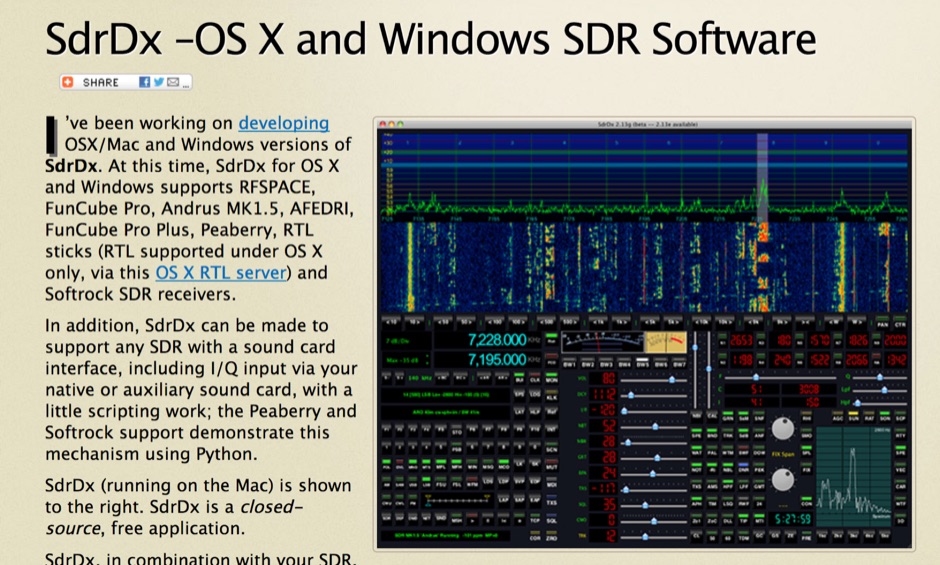 OSX/Mac and Windows versions of SdrDx. Supports RFSPACE, FunCube Pro, Andrus MK1.5, AFEDRI, FunCube Pro Plus, Peaberry, RTL sticks (RTL supported under OS X only, via this OS X RTL server) and Softrock SDR receivers.
 -
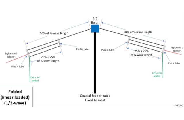 Experiments on HF antennas for restricted spaces. In this article author experiments antennas for 80-10 meters band having just a very small garden and several restrictions. Basic antennas consists of laded multiband dipoles and fan dipole antennas
 -
 A 6 dB gain Moxon rectangle antenna, designed for the 2-meter band, offers an excellent solution for hams seeking a compact, directional antenna for **SSB** operation, particularly in restricted spaces like an attic. This design emphasizes ease of construction using readily available materials such as 4mm OD brass tubing and plywood, making it an accessible project for many radio amateurs. The antenna's inherent characteristics, including a high front-to-back ratio of 37 dB and a 50-ohm feed impedance, contribute to its effectiveness in mitigating local noise and focusing radiated power. The project leverages the free MoxGen program for precise dimension calculations based on the desired frequency and wire size, and utilizes 4nec2 for pattern analysis, confirming a 3 dB beamwidth of 80 degrees. Construction involves bending brass tubing for the driven and passive elements, mounting them on an 800 x 350 mm plywood boom, and securing them with cable clips and epoxy resin. Initial SWR measurements at 144.3 MHz showed 1.6:1, which improved to 1.3:1 at 145.3 MHz across a flat band from 144.1 MHz to 145.5 MHz after adding a **coaxial choke** to mitigate common mode current.
 -
 Otto engineering is comprised of two divisions otto controls and otto communications. otto controls designs and manufactures a full line of switches and grips used in heavy equipment, aerospace, marine, medical and other demanding applications. otto communications designs and manufactures audio accessories for two-way radios used in public safety, police, fire, retail, hospitality manufacturing and other markets.
 -
 This project details the construction of a **full-sized 40-meter vertical antenna**, born from a renewed interest in 7 MHz operation and a desire for improved effectiveness over simple dipoles. The author, K5DKZ, initially focused on VHF experimentation, which provided an inventory of aluminum tubing and fiberglass spreaders for this endeavor. Before this vertical, K5DKZ utilized an 80/40 meter inverted-vee trap dipole and a 40-meter broadband dipole, but now primarily uses a pair of full-sized, phased, quarter-wave verticals spaced 35 feet apart for serious 40-meter work. The construction involves a base-heavy design for stability, using a 44.5-inch section of 1-1/4 inch steel TV mast driven into 1-3/8 inch aluminum tubing, insulated by a 105-inch section of Schedule 40 PVC pipe. The assembly reaches 31 feet, close to the 32 feet required for a quarter-wavelength on 40 meters, with fine-tuning achieved by winding wire onto a fiberglass spreader. The design is explicitly presented as a foundation for a two-element 40-meter Yagi beam, outlining modifications like substituting aluminum for steel in the base and using an inductive hairpin match for the driven element. The article also discusses tuning considerations for a large 40-meter beam, noting the 100 to 200 kHz upward frequency shift when raised, and suggesting methods for installation on a tower. The author emphasizes the cost-effectiveness and good performance of the monopole approach, especially when multiple verticals are needed.
 -
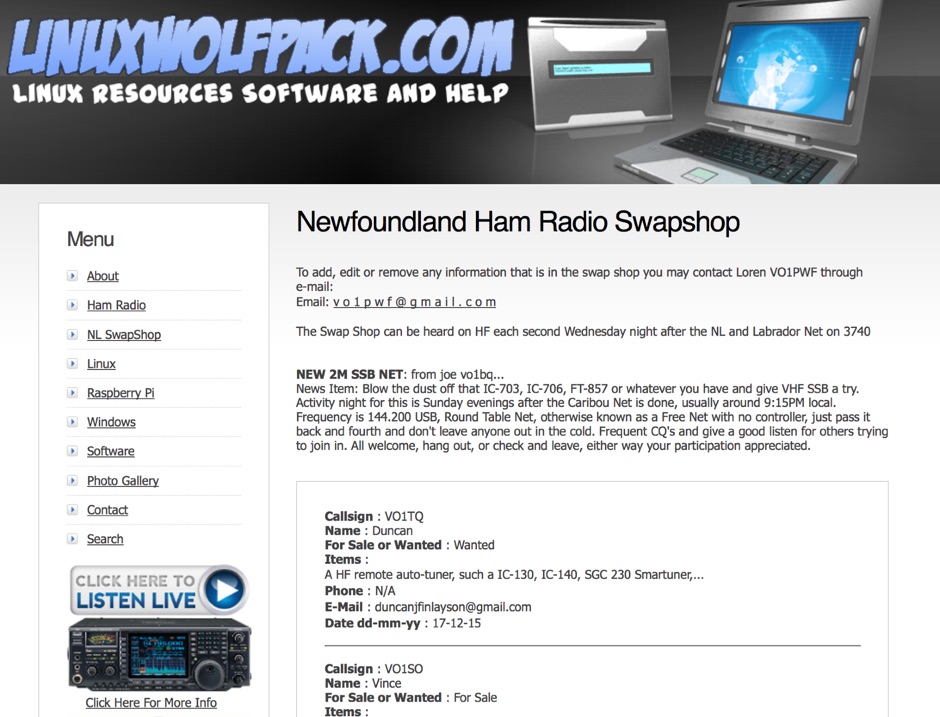 The NL Ham Radio Swap Shop is an online platform dedicated to connecting amateur radio operators in Newfoundland and Labrador with opportunities to buy, sell, and trade radio equipment. This service caters to both seasoned operators and newcomers, providing a space for exchanging second-hand gear, military radios, antique radios, and radio tubes. Users can browse listings, post their own items, and find unique equipment that may not be available in traditional retail outlets. In addition to facilitating transactions, the Swap Shop also serves as a community hub for local hams. It encourages networking among operators, sharing of knowledge, and collaboration on projects. Whether you are looking for a rare piece of equipment or simply want to declutter your shack, the NL Ham Radio Swap Shop is an essential resource for anyone involved in the amateur radio hobby in the region.
 -
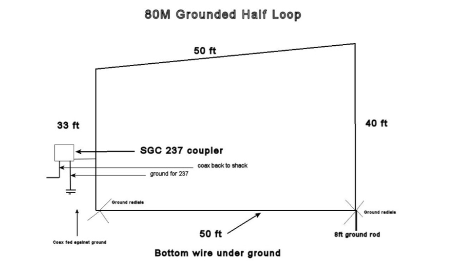 The grounded half loop describe in this article is basically a half wave length wire on 80 Meters. The 80M grounded half loop antenna, inspired by a 1984 QST article by SM0AQW, is a compact solution for limited spaces. Comprising a 127-foot wire fed against ground and supported by radials, it balances performance and practicality. Despite compromises in length and proximity to structures, the antenna delivers strong signal reports and effective multi-band tuning using an SGC 237 antenna coupler. Ideal for CW operation, it offers low SWR on 80-10M, though noise levels and safety considerations warrant attention. This versatile design excels in constrained environments.
 -
 This page documents Amateur Radio data digipeated by the International Space Station
 -

-
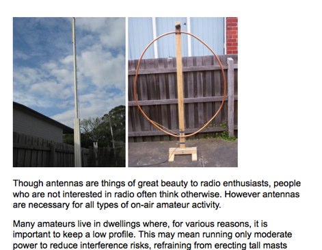 Antennas for restricted lots, apartments and indoor antennas by VK3YE
 -
 This PDF document details the construction of a **70 MHz** Big Wheel antenna, a horizontally polarized omnidirectional array. The design utilizes three full-wave loops, each approximately **2160 mm** in diameter, arranged in a triangular configuration. The resource provides mechanical dimensions for the antenna elements and a comprehensive bill of materials, specifying component quantities and types, such as M8 stainless steel bolts, 15x15x1.5 mm square aluminum tubing for spacers, and 8 mm aluminum rod for the arcs. The central hub is constructed from two 160x160x8 mm aluminum plates, with four 40 mm long polyamide insulators supporting the radiating elements. The feed system incorporates a 50 mm diameter aluminum pipe for mounting and a matching stub constructed from a 120x20x2 mm aluminum sheet, connected via M8x10 mm bolts. The resource includes a diagram illustrating the mechanical dimensions and assembly points, including the N-connector fixing point and the center conductor attachment. The project was published on May 25, 2011, by Peter OE5MPL and Rudi OE5VRL. DXZone Focus: PDF | 70 MHz Big Wheel | Mechanical Dimensions | **2160 mm** loop diameter
 -
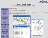 Demonstrates the _SQUIRL Field Day Logger_, a specialized software tool designed for efficient contact logging during the annual ARRL Field Day event. The resource details its core functionality, which includes real-time logging to easily readable text files, with filenames structured by callsign, band, and mode (e.g., K8DAA-20M-SSB.txt). It highlights features such as a real-time history grid of previous contacts, a dynamic USA and Canada map displaying contact locations, and a duplicate checker that provides audio notifications and pre-fills class/section data for previously worked stations. The software also includes an ADIF export function, enabling users to transfer logs to other general-purpose logging programs. The software's design emphasizes simplicity and ease of use, allowing for rapid on-the-spot training, as noted by users like W4CMB. It supports various operating systems, including Windows 98 through 8, and has been successfully run on Linux via _Wine_. Key usability enhancements include a "double-size" feature for improved readability and a "Space Mode" for quick field navigation. The version history indicates continuous development from 2001 to 2013, with significant additions like the real-time Field Day Map in 2003 and ADIF export in 2004, which allows for seamless integration with other logging platforms.
 -
 The X80 multi-band HF vertical antenna, a commercial iteration of the Rybakov design, exhibits a physical length of 5.5 meters, or approximately 18 feet, and is constructed from aluminum tubing. It operates as a non-resonant vertical, requiring an external antenna tuner for impedance matching across its intended operating frequencies. The antenna's design incorporates a 1:4 UNUN at its base, facilitating a nominal 50-ohm feed point impedance for the coaxial cable. Performance observations indicate effective operation on 40 meters, 20 meters, 15 meters, and 10 meters, with reduced efficiency on 80 meters and 160 meters due to its relatively short electrical length for these lower bands. Comparative analysis with a G5RV dipole and a half-wave end-fed antenna reveals the X80 offers a lower take-off angle, beneficial for DX contacts, particularly on the higher HF bands. Field tests conducted with an Icom IC-706MKIIG transceiver and an LDG AT-100ProII autotuner demonstrate the X80's ability to achieve acceptable SWR across 80m through 10m. The antenna's compact footprint and ease of deployment make it suitable for restricted spaces or portable operations, though its performance on 80 meters is noted as a compromise compared to full-size resonant antennas.
 -
 Constructing a compact, single-feed triband Moxon antenna for 20, 15, and 10 meters is detailed by DU1RZ, drawing from his personal experience with space-constrained antenna projects. Initially fascinated by cubical quads, the author transitioned to Moxon designs in 2005 after realizing his roof space was insufficient for a bulky quad. His first experimental monoband Moxon for 15 meters, built from repurposed materials, provided solid DX QSOs for seven years, despite being slightly below the 21 MHz band center. The project outlines the design process, including using the _MOXGEN Calculator_ for element dimensions and material selection, such as #14 AWG enamel copper wire and fishing poles for spreaders. DU1RZ shares insights from simulations with DL2GMS regarding insulated versus non-insulated wire performance, noting that insulated wire can shift resonant frequencies lower. The assembly instructions cover preparing wire elements, connecting feed points, and tuning the antenna, with initial SWR measurements taken at 10 feet and final readings on a mast showing excellent results: 1.0:1 on 14.225 MHz, 1.1:1 on 21.250 MHz, and 1.3:1 on 28.50 MHz. Transmission tests with 4F1BYN indicated a front-to-back ratio of approximately 2 S units with 10 watts output. The author emphasizes adaptability, encouraging builders to use readily available materials rather than strictly replicating his setup. Key observations from DU1RZ and DL2GMS highlight the antenna's strong performance across 20, 15, and 10 meters, good front-to-back ratio, full bandwidth on 20 and 15 meters, and its small turning radius of about 4.18 meters (13.54 feet), making it suitable for limited antenna space. Its lightweight construction and low wind load are also noted as significant advantages.
 -
 Software Defined Radio manufacturer, SDR-IQ NetSDR SDR-IP and IF-2000
 -
 The JSCARC, located at NASA's Johnson Space Center, Houston, Texas, supports the U.S. Space Program and the International Space Station.
 -
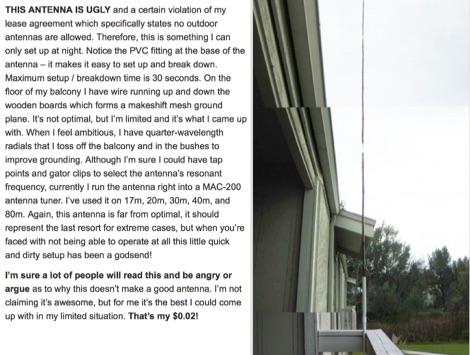 Antenna for limited space, made from 24AWG wire helically wrapped around the top element of a 3-element cane pole, is basically a fully-loaded vertical and performance are limited and should represent the last resort for extreme cases.
 -
 Designing and constructing portable wire antennas for HF operations, this resource explores several configurations including the _foldback dipole_ for space-constrained setups and an inductively shortened dual-band dipole for 20m and 40m. It details the calculation of inductance for shortened elements, providing a Visual Basic 6.0 program screenshot that illustrates determining coil parameters like turns and length for a **25.5 uH** inductor. The document emphasizes practical considerations such as adjusting wire lengths for optimal SWR, noting that a dual-band dipole achieved SWR below 2:1 on both 20m and 40m, with careful adjustment bringing it under 1.5:1. Further, the resource describes a half-wave antenna matched with a coaxial stub, a method often referred to as the _Fuchskreis_ in German amateur radio circles, to transform the high feedpoint impedance to 50 Ohms. This monoband solution, for a 20m application, uses a stub length of **2.98m** (0.216 lambda multiplied by coax velocity factor) and a shorted stub of approximately 48cm. The coaxial stub design is highlighted for its resilience to ground proximity, allowing it to be rolled up or laid on the ground with minimal SWR impact, making it highly suitable for portable QRP operations.
 -
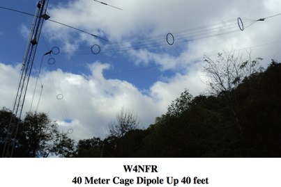 The antenna consists of 6 runs of stranded wires spaced by plastic Hula Hoop spacers made of poly tubing
 -
 Shortwave listeners and amateur radio operators interested in _numbers stations_ can engage with this mailing list, which serves as a platform for discussing the enigmatic transmissions. The resource facilitates the exchange of information regarding these unusual broadcasts, often associated with intelligence agencies, by allowing members to share observations, decode attempts, and theories. It provides a community space for those who monitor the HF spectrum for these unique, often automated, voice or digital signals. Participation on the list enables members to contribute to a collective understanding of numbers station activity, including changes in frequencies, broadcast schedules, and message formats. While specific technical analysis or signal processing techniques are discussed by members, the primary function is information sharing. The list is administered by csmolinski at blackcatsystems.com, and prior postings are archived for reference, allowing new members to review historical discussions and data.
 -
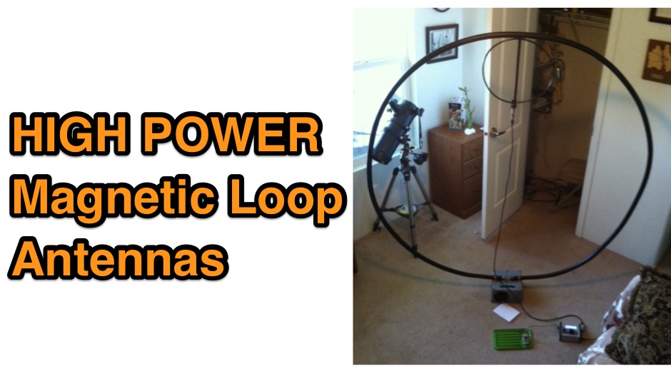 Magnetic Loop Antennas for The Radio Operator with Limited Space, a two part series of articles on how to construct a magnetic loop antenna, including directions on selecting high voltage tuning capacitor
 -
 This page is about the RSGB's Propagation Studies Committee, its work, services and current projects, together with guides to where to find more about matters relating to propagation on the Internet at all levels from introductory to professional. Watch this space!
 -
 The resource details the construction of a multiband trap-style Inverted-V antenna designed for operation on 3.5 MHz, 7 MHz, 14 MHz, 21 MHz, and 28 MHz. It presents specific winding data for the traps, including the number of turns, wire gauge, and coil former dimensions, crucial for achieving resonance on the target bands. The document provides a parts list and a diagram illustrating the antenna's physical layout and trap placement. It outlines the process for building the traps using PVC pipe formers and specifies the required capacitor values for each trap. The design emphasizes a practical approach to achieving multiband operation with a single feedline, a common goal for HF operators with limited space. The document includes a table with antenna segment lengths for each band, allowing for precise replication of the design. It also offers insights into tuning and adjustment, ensuring the antenna performs optimally across the designated amateur radio bands.