Search results
Query: RF antenna
Links: 794 | Categories: 17
Categories
- Antennas > End-Fed > End Fed Half Wave Antenna
- Radio Equipment > HF YAGI Antennas
- Shopping and Services > Accessories
- Radio Equipment > HF Portable Antenna > Buddipole
- Antennas > Feed Lines > Choke
- Radio Equipment > HF Vertical Antenna > Cushcraft R5
- Antennas > EH
- Radio Equipment > HF Vertical Antenna > GAP Titan
- Technical Reference > Grounding
- Manufacturers > Test Equipment > Impedance Analyzers
- Antennas > Theory > Impedance matching
- Antennas > OCF
- Manufacturers > Remote Control
- Antennas > Repair and Maintenance
- Technical Reference > Test Equipment
- Software > Vector Network Analyzer
- Manufacturers > Wattmeters
-
 Operating amateur radio satellites effectively requires precise knowledge of their orbital mechanics and pass times. Gpredict, a real-time satellite tracking and orbit prediction application, addresses this need by allowing operators to monitor numerous satellites simultaneously. It displays critical data such as position and pass details through various visualizations, including lists, tables, maps, and _polar plots_. Unlike many other satellite tracking programs, Gpredict introduces the concept of visualization modules. These modules enable users to group satellites and configure each group independently, offering unparalleled flexibility in how orbital data is presented. This modular approach supports tracking satellites from multiple observer locations concurrently, which is particularly useful for stations with diverse antenna setups or remote operations. Originally a GUI client for John Magliacane's _Predict_ program, Gpredict evolved to integrate its own tracking code for improved performance. The software is distributed under the GNU General Public License, ensuring it remains free and modifiable for the amateur radio community.
 -
 Accessories for your hamshack, such as Band Decoders, various types of Antenna Switches, Antenna Stacking devices, special devices designed dedicated for the SO2R operating technique, USB Interfaces, cw keyers and many others
 -

-
 The perfect tool when you want to put up a wire antenna easily, quickly and safely! EZ HANG can be used to "shoot" a line over a tree or other object over 100 feet high
 -
 The 6 Band Inverted L Antenna MK3 is a versatile multiband antenna designed for amateur radio operators. This antenna covers 160m, 80m, 40m, 20m, 15m, and 10m bands, making it suitable for a wide range of HF communications. The design is based on a W3DZZ configuration, incorporating traps for optimal performance. The MK3 version features a sturdy 5/8th CB mast, replacing the original timber mast, which enhances durability against harsh weather conditions. The antenna's construction allows for effective operation, particularly on the 40m band, where it has been successfully used to contact distant locations including ZL, VK, and Antarctica. Constructing this antenna requires careful attention to detail, especially regarding the radials and grounding. The traps resonate at specific frequencies, and additional resources are available for building coaxial traps. The antenna is designed to work efficiently without an ATU on the lower bands, while higher bands may require tuning. This project is ideal for both beginner and intermediate operators looking to enhance their station with a reliable multiband antenna.
 -
 Constructing a linear focus parabolic antenna for WiFi operation involves precise metalwork, as detailed in this project. The author, AB9IL, shares a build that can be completed in a few hours, emphasizing the hands-on process of shaping and assembling metal components. This design aims to provide enhanced signal range for 2.4 GHz wireless networks, a common challenge in many ham shacks and home setups. The project outlines the practical steps required, from initial measurements to the final assembly, including cutting, bending, and bolting various metal parts. While specific gain figures are not provided, the parabolic design inherently offers significant _directional gain_ compared to omnidirectional antennas, making it suitable for point-to-point links or extending network coverage over distances. The construction process focuses on readily available materials and basic shop tools, aligning with the DIY spirit prevalent in amateur radio. This antenna project is presented as a straightforward build, requiring attention to detail in fabrication to achieve optimal performance.
 -
 RF Choke to prevent hf currents on the feedline. This Magnetic Longwire Balun (MLB) makes it possible to efficiently use a coaxial lead-in cable with all forms of longwires, T-forms or other types of wire antennas, without the need for an antenna tuner.
 -
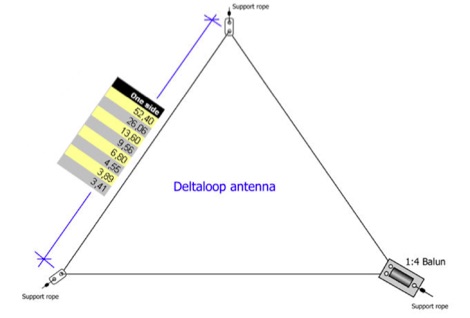 A multi band delta loop antenna that work on 20 and 40 meters band, that can be used either on 15 meters with poor performances
 -
 W1ZY's 40 Meter MOXON is the product of 9 months of experimentation. The final array is reversible and constructed from No. 12 insulated wire fed through two RF current baluns
 -
 The document details the optimization and construction of the _Maria Maluca_ antenna, a compact 6-band (20m-6m) directional beam. It presents a comparative analysis of shortwave antenna principles, highlighting the efficiency gains achieved by using an open feeder line and tuner as a resonant unit, contrasting this with the losses associated with traps or capacitive loads in multiband antennas. The resource specifically revisits an older South American 2-element design for 10, 15, and 20 meters, applying modern NEC-based software to develop a six-band version. Performance data is meticulously tabulated, showing impedance, free space gain, gain at 12m height, elevation angle, and front-to-back (F/B) ratio for each band from 20m through 6m. For instance, on 15m, the antenna achieves 5.1 dBd free space gain and 13.72 dB F/B ratio. The construction section provides practical guidance on element assembly using aluminum pipes and hose clamps, detailing the use of a heavy-duty glass fiber reinforced polyamide rod for electrical separation and bending strength. It also specifies the use of 450-ohm _Wireman_ line CQ 552 for the transmission line. The document includes diagrams for rod fixing, an air-wound balun, and a vertical elevation diagram for the 15m band, illustrating its DX qualification. It also discusses the antenna's suitability for portable and expedition operations, noting its compact transport dimensions (max 1.50m length, 12 lb weight) and quick assembly time (under 15 minutes). The author, Dipl.Ing. Helmut Oeller, DC6NY, is identified as a source for material kits.
 -
 Theory, Modeling, and Practical Applications By W5JCK, presentation in PDF File. This presentation focuses on Near-Vertical Incidence Skywave (NVIS) antennas, which are crucial for short-range radio communications, particularly in military and emergency contexts. It explores NVIS theory, antenna models, and installation criteria while debunking common myths about reflectors. Key topics include usable frequency bands, optimal installation heights, and the impact of soil quality on performance. The presentation outlines the best bands for daytime and nighttime use, emphasizing the importance of understanding propagation characteristics to enhance communication effectiveness within 200 to 300 miles.
 -

-
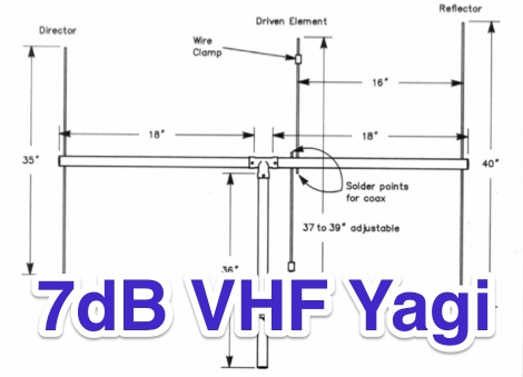 7 dB for 7 Bucks, a 2 meter beam antenna for the cost of a fast food meal!
 -
 A simple drawing of a shortened antenna for 40 meters by using a PVC tube
 -
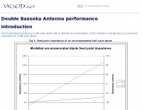 The Double Bazooka Dipole is a half wave dipole with an attempt at compensation of the reactance change that occurs around resonance for a half wave dipole.
 -
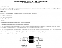 There are lots of good designs for matching transformers for receiving antennas. Make it yourself it's cheap and easy, and very high performance. This is the design used in the TRX-9 transformers.
 -
 A base station antenna you can easily build for 146,220 or 440 MHz, with performance similar to a J-pole but smaller and less obstrusive
 -
 A quarter-wave vertical antenna design for HF operation offers a practical solution for radio amateurs seeking a compact and efficient multi-band radiator. This project details the construction of a 5-band HF vertical, drawing inspiration from established commercial products such as the _DX COMMANDER_ and the MV6. The design emphasizes ease of assembly and disassembly, making it suitable for portable operations or installations with limited space. The article provides insights into various construction methods and offers practical tips for building a robust yet lightweight antenna. It highlights the benefits of a vertical configuration for DX contacts, particularly on the lower HF bands, and discusses real-world performance observations. The antenna is designed to cover multiple HF bands, providing versatility for various operating scenarios. Operators can achieve significant DX results with this type of antenna, often comparable to more complex arrays, especially when deployed with an effective ground system. The project aims to empower hams to build a capable antenna without significant financial outlay.
 -
 The Charles Gizmotchy high performance horizontal and vertical beam antennas. Two, Six, Ten and eleven meters antennas
 -
 How to homebrew an hex beam antenna for 20 17 15 12 10 meters band by VA7ST
 -
 VE7CA experiments on 160 meters band antennas, looking for better performances on reception.
 -
 Constructing a Lindenblad antenna for 137MHz NOAA satellite reception involves specific design considerations for optimal performance. The resource details the use of 4mm galvanised steel fencing wire, 300-ohm television ribbon cable, and wood/plastic components for the antenna structure. Key dimensions for a 137.58MHz-resonant antenna are provided, derived from the ARRL Satellite Handbook, specifying s, l, w, and d as 42, 926, 893, and 654mm respectively. The antenna is designed for Right Hand Circularly Polarised (RHCP) signals, requiring the four folded dipole elements to be tilted clockwise by 30 degrees. A significant aspect covered is impedance matching between the antenna's 75-ohm impedance and a typical 50-ohm receiver input. A twelfth-wave matching transformer, constructed from 117mm sections of 50-ohm RG-58 and 75-ohm RG-59 coax with a 0.66 velocity factor, is described. The article also addresses coaxial cable and connector selection, recommending 75-ohm Type-N connectors for RG-6 cable in professional setups and F56/F59 connectors for general use, while strongly advising against PL-259/SO-259 connectors for VHF. Strategies for mitigating Radio Frequency Interference (RFI) are discussed, including antenna placement to shield from local TV transmitters and the use of commercial or DIY band-pass filters, such as cavity resonators or helical notch filters, along with ferrite chokes on coaxial cables. Antenna orientation is explored, noting the Lindenblad's 'cone of silence' directly overhead and its maximized sensitivity towards the horizon. An experimental vertical tilt of 90 degrees is presented as a method to improve overhead reception and reduce interference from strong horizontal signals, particularly relevant in high RFI environments like the Siding Spring Observatory site.
 -
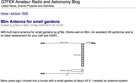 A 46ft multi-band antenna for small gardens that works on 80m. An excellent DX performer and is an ideal replacement for your half size G5RV by G7FEK
 -
 ERP Calculator is an Amateur Radio software utility designed to perform a side-by-side comparison of two Ham Radio antenna systems. ERP Calculator comes pre-programmed with data files including published data for several popular brands and types of coax cable as well as several popular antenna system brands and models. ERP Calculator displays values of ERP, Antenna Power Gain, Antenna Feed point Power, Antenna System Gain in dB, Antenna Gain in dBd, SWR Attenuation in dB, SWR Power Attenuation, Coax Loss in dB, and Coax Power Loss
 -
 Excel sheet containing technical comparisons of commercial HF portable antennas compiled by ON4SKY. Includes pictures, manufacturer, db gain, band coverage, F/B ratio, price, weight and dimensions.
 -
 An antenna system is more easily interfaced to a radio when the input reactance at the feedline terminals is low or close to series resonance
 -
 This page describes a simple way to determine the main RF characteristics of a Wifi (IEEE802.11b/g wireless LAN) antenna.
 -
 This resource details the computer-optimized design of the _ZS6BKW_ multiband dipole, an evolution of the classic _G5RV_ antenna. It begins by referencing the original 1958 RSGB Bulletin article by Louis Varney G5RV, explaining the operational principles of the G5RV's flat-top and open-wire feedline on 20m and 40m, noting its impedance transformation characteristics for valve amplifiers of that era. The article then transitions to the rationale for optimizing the design for contemporary solid-state transceivers requiring a 50 Ohm match. The core of the project involves using computer modeling to determine optimal lengths for the flat-top and matching section, aiming for a VSWR of less than 2:1 on multiple HF bands. It discusses the process of calculating feedpoint impedance based on antenna length and frequency, referencing professional literature from Professor R.W.P. King at Harvard University. The analysis also considers the characteristic impedance (Z(O)) of the open-wire line, identifying a broad peak of adequate values between 275 and 400 Ohms. Specific design parameters for the improved ZS6BKW are presented, including a shorter flat-top and a longer matching section compared to the original G5RV, with a velocity factor of 0.85 for the 300 Ohm tape. The article confirms acceptable matches on 7, 14, 18, 24, and 28 MHz bands when erected horizontally at 13m, and also discusses performance in an inverted-V configuration, noting frequency shifts. The author, Brian Austin ZS6BKW, emphasizes the antenna's suitability for modern 50 Ohm coaxial cable without a balun.
 -
 JJ0DRC's HF multi-band delta loop antenna project, initially conceived during the waning peak of Cycle 23, addresses the common challenge of achieving effective DX operation from a small residential lot in Japan. Dissatisfied with a ground plane antenna's performance in SSB pile-ups, the author sought a beam-like solution without a tower, drawing inspiration from a JJ1VKL article in CQ Ham Radio Sep. 2000. The antenna, constructed in October 2000, employs two 7.2-meter fishing rods (37% carbon fiber, reinforced with cyano-acrylate glue and aluminum tape) and 1mm enameled wire, fed by an Icom AH-4 external antenna tuner. While the exact beam pattern remains unmeasured, JJ0DRC observed a significantly higher callback rate compared to dipole antennas, particularly on higher bands. The system's circumference length of 15-20m is crucial for maintaining a good beam pattern across HF bands, though performance on lower bands like 80m, 40m, and 30m becomes less directional as the length deviates from a full wavelength. Ongoing maintenance addressed degradation issues, including aluminum tape cracking and wire breakage at connection points due to strong winds (often exceeding 10-15m/s in winter). The author reinforced rod connections with IRECTOR PIPE SYSTEM components and INSU-ROCK ties, and improved wire attachment methods using Cremona rope and epoxy bond to enhance durability.
 -
 Presents the design and construction of the OK2FJ Bigatas, a portable, automatically tuned vertical antenna covering 80 through 10 meters. It details two distinct control systems: one utilizing BCD band data from Yaesu FT-857/897 transceivers, and another employing voltage level sensing for the Yaesu FT-817. The resource provides specific instructions for building the antenna's radiating element, loading coil with switchable taps, and the control circuitry, emphasizing the use of readily available components. The article outlines the physical construction of the antenna, including the use of duralumin tubes for the radiator and a PVC tube for the coil form. It specifies coil winding details, tap points, and the integration of radial wires for ground plane operation. The control electronics section provides schematics and component lists for both the BCD decoder (using a 74LS42 IC) and the voltage comparator (using an _LM3914_ bargraph driver), enabling rapid, automatic band switching without the minute-long tuning delays common in other systems. Crucially, the antenna achieves rapid band changes, with typical SWR values centered on common operating segments, such as **3.7 MHz** for 80m SSB. It also discusses modifications for CW operation on 80m and the trade-offs between antenna efficiency and full-range automatic tuning on higher HF bands, where manual adjustment of radiator length is suggested for optimal performance on 15m, 12m, and 10m. The resource includes construction photos and a discussion of cable requirements for reliable operation.
 -
 Presented here is a high-performance, circularly polarized omni-directional antenna that is easy to build, easy to tune, inexpensive, and will work all the mode J Low Earth Orbit (LEO) satellites
 -
 Thermocouple ammeters are very rare these days, but the job they were perfect for - measuring antenna currents - is still a modern requirement especially in respect to groundplane currents. By David A. Reid PA3HBB G0BZF
 -
 Overview, summary, tutorial about the log periodic antenna or aerial used for wideband RF antenna applications
 -
 Amateur Television (ATV) operations, particularly within the Arizona region, require dedicated resources for technical information, operational guidance, and community engagement. This club provides a focal point for hams interested in transmitting and receiving video signals on amateur bands. Members engage in local ATV repeaters, participate in technical discussions, and share knowledge on video modulation schemes, antenna designs, and station configurations. The club supports activities ranging from local simplex contacts to wider area repeater usage, fostering skill development in this specialized mode. The organization maintains a roster of club officers and offers membership opportunities to local amateurs. It also curates offsite links to other ATV resources, expanding the knowledge base available to its members and the broader amateur community. The club's emphasis on ATV helps propagate interest and technical expertise in a mode that combines traditional RF engineering with video technology.
 -
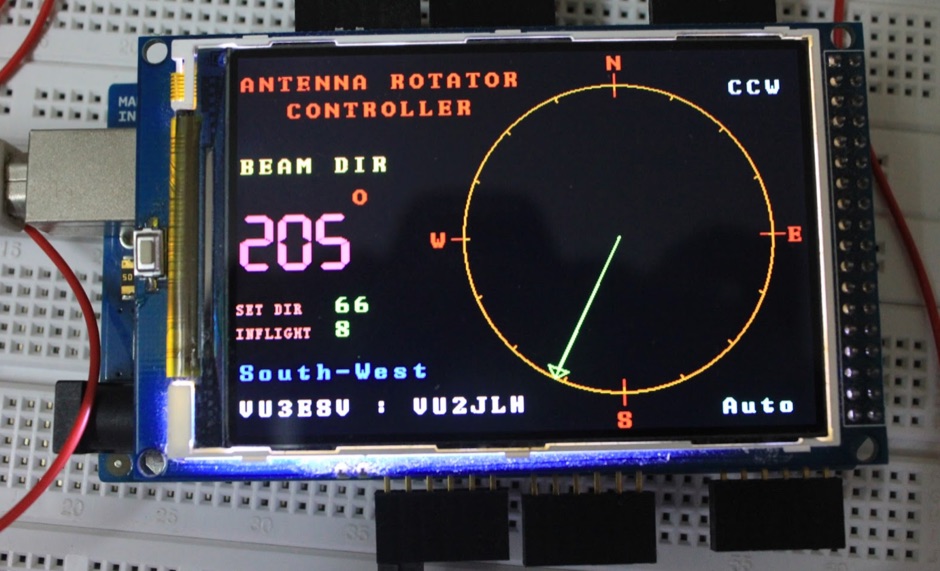 This is an attempt to build an Antenna rotator controller using Arduino Mega 2560 with a nice user interface showing the actual position of the antenna.
 -
 Presents a comprehensive guide for constructing a broadband Hex Beam antenna, a popular directional array for HF operation. This design offers a compact footprint and excellent gain characteristics, making it suitable for limited space installations while providing significant performance advantages over omnidirectional antennas. The resource details the specific dimensions for a five-band Hex Beam covering 20, 17, 15, 12, 10, and 6 meters, emphasizing the critical element spacing and wire lengths required for proper resonance and pattern. It outlines the construction of the center post, spreaders, and wire elements, along with the feed point assembly, ensuring proper impedance matching. The project aims for a forward gain of approximately **5.5 dBi** on most bands, with a front-to-back ratio often exceeding _20 dB_. Building this antenna requires careful measurement and assembly, but the resulting performance provides a substantial upgrade for DXing and contesting.
 -
 Engaging in **QRP** operations, where amateur radio transceivers transmit at five watts or less, presents a unique challenge and satisfaction for many radio amateurs. This mode emphasizes efficient antenna systems, keen operating skills, and often, the art of **homebrewing** equipment to maximize performance under power constraints. Operators frequently utilize CW (Morse code) for its superior signal-to-noise ratio, enabling reliable contacts over long distances with minimal power. The VK QRP Club, formally known as the CW Operators' QRP Club Inc., serves as a focal point for Australian amateurs passionate about these low-power pursuits. The club fosters a community where members can share insights on antenna design, circuit construction, and operating techniques specific to QRP. It provides resources such as information on club nets and frequencies, Morse practice materials, and a platform for exchanging ideas among enthusiasts. Membership offers access to a network of like-minded individuals, promoting the continued development and enjoyment of QRP within the amateur radio hobby. The club's activities encourage experimentation and skill refinement, vital aspects of successful low-power communication.
 -
 MARS, Israel's Antenna and RF System manufacturer, flat antennas for cellular, military broadband, multiband MF high power antenna
 -
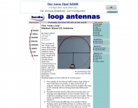 The concept of the "Hula Loop" came after many years of building medium wave loops of varying size, shape and performance. Usually these loops are constructed on a square wooden frame, with wire being wrapped around the periphery
 -
 This project outlines the construction of a 3-element reversible quad antenna specifically designed for the 40-meter band. The materials required include pushup towers, pressure-treated posts, insulated wire, and various electrical components such as relays and a balun. The construction process is straightforward, beginning with the installation of the posts in a straight line, followed by the assembly of the antenna elements and their elevation to the desired height. The antenna's design allows for directional signal reception, making it ideal for operators looking to enhance their communication capabilities on the 40-meter band. The project includes detailed instructions on tuning the antenna for optimal performance, ensuring that operators can achieve the lowest SWR possible. Additionally, the design can be adapted for other bands by extrapolating dimensions, providing versatility for amateur radio enthusiasts. Overall, this reversible quad antenna project is suitable for both beginners and experienced operators, offering a practical solution for improving signal strength and directionality in 40-meter communications.
 -
 D3+ High Performance Antennas for Field Day. This article describes versatile broadband wire antennas. These antennas will double your effective radiated power over a dipole, will be easy and inexpensive to build and install, and will be simple to match.
 -
 Illustrates the specific wiring and configuration steps required to interface an SGC-230 Smartuner with an Icom IC-706 HF/VHF/UHF transceiver. The document details the necessary connections for power, control, and RF signal paths between the two devices, ensuring proper impedance matching and automatic antenna tuning functionality. It specifies the pin assignments for the IC-706's ACC socket and the SGC-230's control port, crucial for successful integration. Outlines the operational considerations for the combined system, including initial setup procedures and potential troubleshooting tips for common connectivity issues. The resource presents a clear, diagrammatic representation of the interconnections, which aids in visual comprehension of the required cable fabrication or modification. Covers the specific settings within the IC-706 menu that need adjustment to enable external tuner control, such as the 'TUNER' function and other relevant parameters. This ensures the transceiver correctly communicates with the SGC-230 for efficient antenna tuning across various amateur bands.
 -
 The Q-signal **QRP** signifies a request to reduce power, and in amateur radio, it defines operating with 5 watts or less for CW and 10 watts or less for SSB. This article addresses common inquiries from new hams regarding the practice, its benefits, and implementation methods. It explains how a 5-watt QRP signal, compared to a 100-watt signal, typically results in only a 13dB drop in signal strength, equating to about two S-units, still providing solid copy under most conditions. Hams choose QRP for various reasons, including seeking a greater challenge in DXing or contesting, reducing band interference, or enabling portable field operations with lightweight, battery-efficient equipment. A modern single-band CW transceiver, key, and antenna can fit into a pocket, offering receiver performance comparable to commercial rigs and extended operation on a small battery. This portability facilitates operations in remote locations where higher-power setups are impractical. Operating QRP can involve simply reducing power on an existing commercial HF rig or building a dedicated QRP transceiver from a kit, such as the **Wilderness Radio SST** with its 2-watt output and 15mA receive current draw. While SSB is viable, CW remains the most popular and efficient mode for QRP due to its superior signal-to-noise ratio. The article lists common QRP calling frequencies across 160m through 10m bands for both CW and SSB, and highlights organizations like QRP ARCI and NorCal that support the QRP community.
 -
 This is a popular antenna design as the performance is very good across the HF bands and requires little or no tuning. It is a dipole fed off center with a 4:1 current balun at the offset feedpoint. The antenna shown covers 80, 40, 20 and 10 meters with 15 meters and WARC bands
 -
 The project outlines the process for constructing a low-power FM broadcast transmitter using a Raspberry Pi Zero, a simple wire antenna, and battery power. It details the software installation steps for PiFM and MPG123, essential for generating and transmitting audio. The resource provides instructions for configuring the Raspberry Pi to broadcast FM signals, including command-line operations for initiating transmission and playing audio files. It specifically focuses on the Raspberry Pi Zero's capabilities for this application, highlighting its cost-effectiveness and minimal hardware requirements. The content presents a practical, hands-on approach to creating a basic FM transmitter, suitable for short-range, experimental broadcasting. It includes guidance on testing the FM output and ensuring proper operation of the software components. The project emphasizes the use of readily available components and open-source software to achieve functional RF output.
 -
 RF engineering solutions, HF VHF antenna systems and radio communications equipment.
 -
 The ZS6BKW wire antenna, a variant of the G5RV, utilizes a specific 13m (42.6 ft) length of 450-ohm window line as its matching section, feeding a 28.5m (93.5 ft) flat-top element. This design aims for lower SWR on 40m, 20m, 17m, 12m, and 10m compared to a standard G5RV, often achieving SWR values below 1.5:1 on these bands without an antenna tuner. The feedpoint impedance transformation provided by the window line allows for direct connection to 50-ohm coax on multiple bands. F4FHH's experience involved constructing the ZS6BKW and evaluating its performance against an _OCF dipole_ (Off-Center Fed) on various HF frequencies. The article includes observations on SWR readings and operational effectiveness, highlighting the ZS6BKW's suitability for multi-band operation. The antenna's overall length, including the flat-top and window line, is approximately **41.5 meters** (136 feet), making it a significant wire antenna for fixed station use. Comparative analysis with the OCF dipole provided practical insights into the ZS6BKW's advantages and limitations, particularly concerning bandwidth and tuner requirements.
 -
 Some antenna manufacturers place baluns at the incorrect location in LPDA arrays, or tell you to route the cable incorrectly. This can cause substantial RFI and all sorts of weird problems like RF into house wiring.
 -
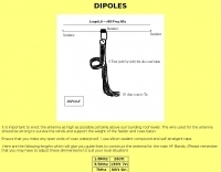 The simple dipole is perhaps the best antenna for consistent performance. Basic page on dipoles by G3PTO
 -
 The AMRAD Active LF Antenna. You can tune into LF activity with this easy-tobuild and erect active antenna. As a bonus, you get MF and HF coverage, to not to mention world-class performance