Search results
Query: antenna amp
Links: 201 | Categories: 4
-
 The Narrabeen JOTA and JOTI camp facilitates global communication for Sydney North Region Scouts and Northern Sydney Girl Guides, utilizing amateur radio and internet technologies. Participants engage in two-way radio contacts, often on **HF** bands, to connect with other scouting and guiding groups worldwide, fostering international goodwill and technical skill development. The event integrates both traditional **ham radio** operations and modern internet-based communication methods, providing a diverse experience for youth members. The resource outlines the specific activities undertaken at the Narrabeen site, including station setup, operating procedures, and the use of digital modes for JOTI. It highlights the educational aspects of the event, such as learning about radio propagation, antenna theory, and basic electronics, all within a structured camp environment. The page also provides logistical information relevant to the Australian context of the event.
 -
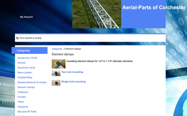
 German antenna parts dealer, provides antenna element holders, element clamps for yagi antennas, junction boxes, aluminium plates and rods. Offers also Rope tensioners, plugs and adapters and any additional part you need when you want to make your own antenna.
 -
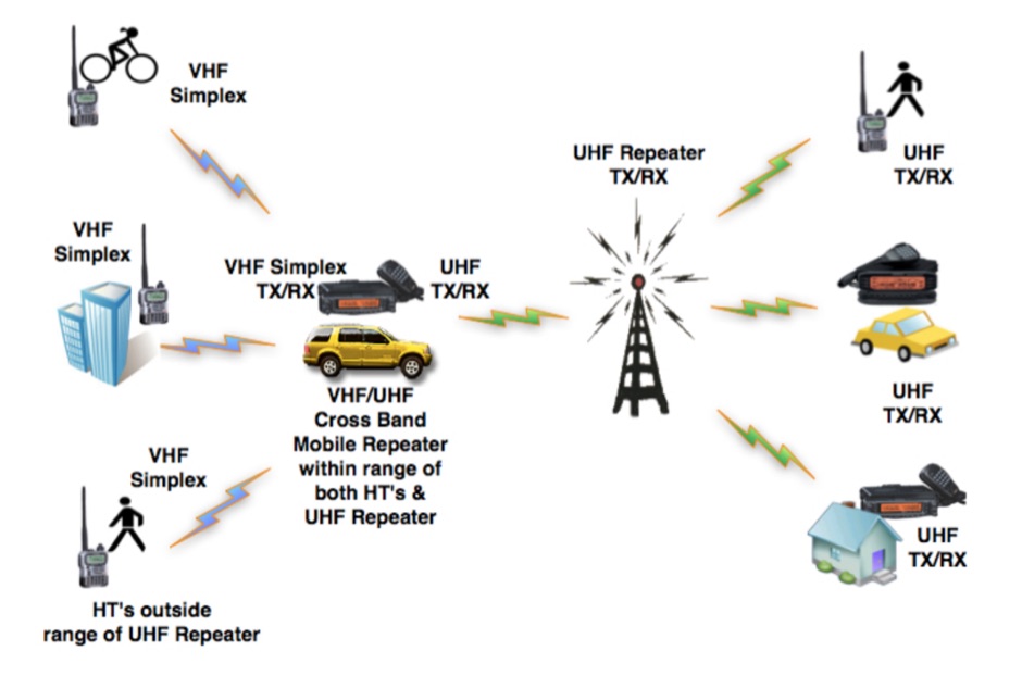 Crossband Repeating is a process where a Ham transmits one signal on one band (typically UHF), and it is received by another radio with a better antenna/power installation, and re-transmitted (typically on VHF) to another radio system, or a repeater. Everyday examples of cross-band repeaters are repeater receive sites that hear the input signals on 2m and retransmit those signals on a frequency higher than 220 MHz.
 -
 The Bazooka antenna, a coaxial dipole, functions as an omnidirectional antenna with vertical or horizontal polarization. Patented in 1939 and refined in 2006, it features a quarter-wavelength coaxial cable with separated conductors. The outer conductor connects to a sleeve, while the inner conductor extends vertically. Initially complex, it has been simplified for versatile use, including military applications. Adding elements can modify its behavior for NVIS or Yagi-Uda configurations. Experiments in 2007 at the Campus de Pesquisas GeofÃsicas in Paula Freitas-PR demonstrated consistent VHF and UHF performance, showing reliable return loss measurements despite variable weather.
 -
 HAM-made engineering products supplies and produces coaxial relays, antenna switches, sequencers, roller inductors, variable capacitors, low noise preamplifiers, RF power rotary switches and coil bodies.
 -
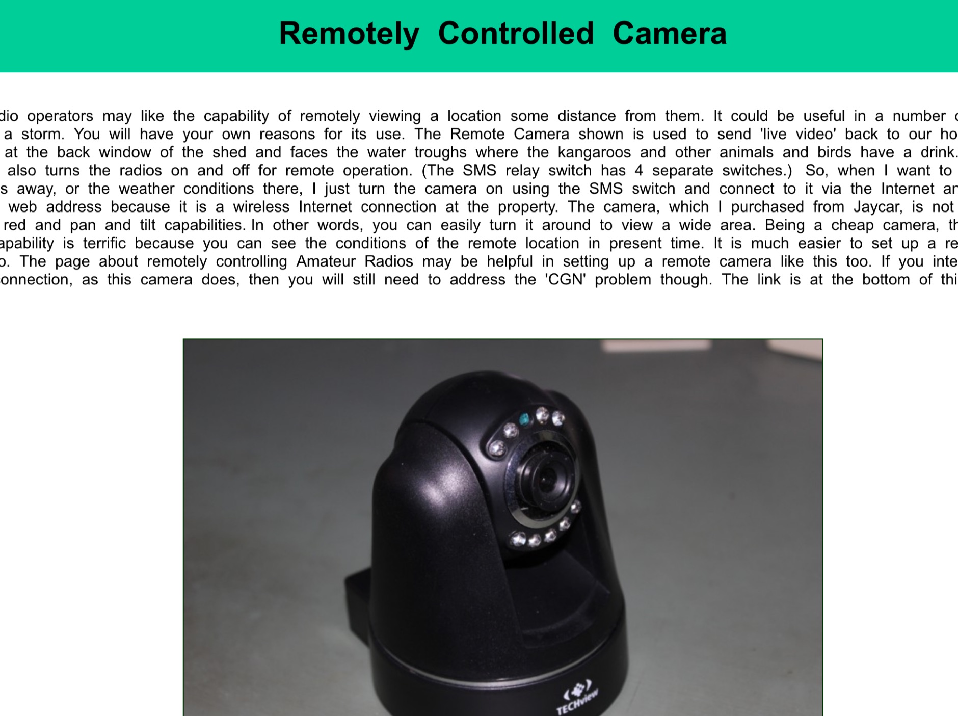 Remote viewing can be useful for Hams, in example remotely viewing antennas during a storm.
 -
 The video showcases the setup of a 300 MHz oscillator, a 100W radiofrequency amplifier, and a dipole antenna for transmitting radio waves, leading to the fluorescence of a nearby light bulb. It demonstrates the presence of standing waves on the dipole antenna and how intensity varies along its length. Additionally, the usage of a copper pipe as a receiving antenna is explored, showing changes in intensity depending on alignment and proximity to the transmitter. Finally, a B field antenna sensitive to magnetic fields is introduced, revealing brightness variations in different orientations. The video offers insightful observations on radio wave transmission and reception phenomena.
 -
 Explains the fundamental purpose of a repeater, detailing how these automated relay stations overcome distance and terrain limitations for VHF/UHF communications. It traces the historical development from early Bell Telephone Labs "relay" stations in 1922 to Art Gentry, W6MEP's, pioneering K6MYK amateur radio repeater in the mid-1950s, which remains active today. The resource clarifies the distinction between simplex and duplex operation, including the unique function of a "parrot repeater" for single-frequency recording and playback. Delving into the internal workings, the guide breaks down a repeater into its core components: the antenna system, feedline (often _Heliax_ or hardline for minimal loss), duplexer, receiver, transmitter, and controller. It emphasizes the critical role of the duplexer in preventing receiver desensitization by isolating transmit and receive signals, even with distinct frequencies. The discussion highlights the importance of high-performance, durable antennas and low-loss feedlines, citing examples of equipment installed in the 1960s and 1970s that are still in perfect working order. Operating a repeater is also covered, with an explanation of frequency offset (e.g., the 600 kHz standard for 2 meters) and the function of _CTCSS_ (PL tone) for access. It outlines standard input/output offsets for various bands, from 6 meters to 23 centimeters, while noting regional variations. The guide also touches on features like autopatch and Digital Voice Recorders (DVRs), providing a solid foundation for understanding repeater technology and usage.
 -
 Building an End-Fed Half-Wave (EFHW) antenna from a kit, as detailed by Frank Bontenbal, PA2DKW, with process photos by Bob Inderbitzen, NQ1R, offers a practical approach for hams. This specific kit, a collaboration between ARRL and HF Kits, targets 10, 15, 20, and 40 meters, making it a versatile option for HF operations. Unlike a center-fed dipole, the EFHW is a half-wavelength antenna fed at one end, which simplifies deployment, particularly for portable use. The construction guide meticulously outlines the assembly of the 49:1 impedance matching network, crucial for transforming the antenna's high impedance (around 2,500 Ohms) to a transceiver-friendly 50 Ohms. Steps include preparing the enclosure by drilling holes for the coaxial connector and antenna connections, followed by the precise winding of enameled copper wire onto a toroid to create the transformer. The guide emphasizes careful insulation removal and soldering for reliable connections. Final assembly involves integrating a 100 pF capacitor for higher band compensation, soldering the transformer's primary and secondary sides, and conducting SWR tests with a 2K7 resistor or a half-wavelength wire. The document also provides examples of wire lengths for different bands, such as 16 feet for 10 meters or 66 feet for 40 meters, demonstrating the transformer's adaptability for various half-wavelength configurations.
 -
 The Steampunk-styled air cannon sending tennis balls flying at 500 mph!
 -
 Online antenna parts store, providing many accessories for amateur radio antenna homebrewing. Boom joiners, aluminium parts, elements clamps, filters, ferrites, fasteners, plasti caps, dipole elements. Based in UL
 -
 Learn how to design and analyze a folded trifilar antenna for the 80-meter band. Based on a description from RAF antennas between 1940 and 1970, this article provides step-by-step guidance on modeling the antenna, calculating resonance frequency, adjusting dimensions, and verifying performance. Perfect for hams looking to improve their antenna setup for better transmission and reception on the 80M band.
 -
 This article explores the conventional wisdom about antenna height in amateur radio operations, challenging the common belief that "higher is always better." Through practical examples and computer modeling, it examines how low-height antennas like Beverage antennas, VP2E, and End-Fed Half Wave (EFHW) configurations can perform effectively in various scenarios. The analysis includes radiation patterns and efficiency considerations for antennas at different heights, particularly focusing on portable operations. The article demonstrates that while height affects antenna performance, lower installations can still provide practical and efficient solutions for specific applications, especially in portable and QRP operations.
 -
 This project explores the construction and performance of an Alford Loop antenna as an alternative to a round loop. The Alford Loop, symmetrically fed at opposite corners, behaves like a small loop despite its larger size. Built using PVC pipes and secured with tire wraps, the antenna integrates an LZ1AQ active amplifier for optimal performance. With deep nulls in its horizontal radiation pattern and improved resonance characteristics, this design has significantly outperformed previous active antennas in reception quality.
 -
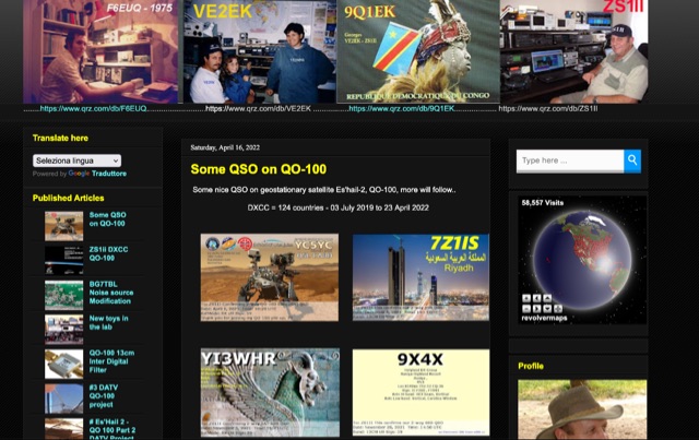 Amateur radio blog about Homebrew equipment,ham radio antennas, satellites, QO-100 operations, rf amplifiers, 2m ldmos amplifier, 70cm ldmos amplifier, 23cm ldmos amplifier
 -
 Showcasing German engineering, ANjo Antennen develops and manufactures a diverse portfolio of amateur radio and commercial antenna products. Their offerings span a wide frequency range from 1.8 MHz to 3000 MHz, emphasizing electrical and mechanical precision for longevity. The company actively participates in events like FUNK.TAG Kassel, providing opportunities for direct engagement and order pickup. ANjo's product line includes high-performance **Yagi antennas** optimized for Tropo and EME, along with multi-stacked Quad antennas designed for contest operations, featuring wide horizontal and narrow vertical beamwidths. They also produce circularly polarized satellite antennas, some with switchable LHCP/RHCP, leveraging their commercial satellite antenna expertise. Beyond amateur applications, ANjo provides flexible, custom antenna solutions for commercial sectors such as BOS, EMC measurements, and telemetry. Their commitment to quality is evident in the Premium-Line antennas, which utilize **1.4301 (V2A) stainless steel** for mast clamps and connectors, ensuring durability and corrosion resistance. They also offer end-fed HF multiband wire antennas, known for their compact footprint and discreet installation.
 -
 Method, Units of Measure, and the Dipole Standard of Reference. This article helps in understanding where does beam gain come from in directional aerials like in example Yagi antennas.
 -
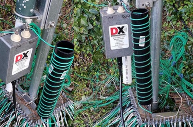 After a storm damaged the antenna, W6AER replaced it with a pre-made capacitance hat from DX Engineering. Using hose clamps and conductive grease, he ensured durability. Experimenting with radials and a coil, he aimed for better performance and resilience.
 -
 Phased array antennas are composed of multiple individual antenna elements that can have their phase and amplitude controlled to steer the main beam direction in real-time. They are used in radar, communications, and electronic warfare, and offer improved gain and reduced side lobes. A comprehensive document on Phased Arrays include techniques to increase the Antenna Gain and change the Radiation Pattern
 -
 From March 2 to March 11, 2018, a Norwegian team operated as Z2LA from Zimbabwe, focusing on 160m through 10m bands using SSB and CW modes. The operation, described as "holiday style," aimed to provide contacts for DXers worldwide seeking a rare DXCC entity. Key equipment included a SUNSDR PRO II, an Elecraft KX3, and an Icom 706 MK2G as a spare radio, supported by two Juma 1000 amplifiers for robust signal output across the bands. Antenna systems were tailored for multi-band operation, featuring an Inv L for 160m and 80m, sloping dipoles for 30m/40m, and a _Hexbeam_ from SP7IDX Technology covering 20m to 10m. For improved reception, the team deployed a SAL 30, two reversible BEV antennas from remoteqth.com, and a BOG from K1FZ, enhancing their ability to hear weak signals. QSL information directs operators to Clublog for log search and M0OXO Charles for OQRS, explicitly requesting no bureau cards. The team comprised LA7THA Rune, LA7WCA Arne, and LA9VPA Thor, successfully making numerous contacts and contributing to the DX community's pursuit of _Zimbabwe_ as a DXCC entity.
 -
 The most basic form of repeater receives communication on one frequency and re-transmits it on a different frequency, a process known as duplex communication. This capability significantly extends the range of handheld and mobile radios, as repeaters are typically situated at elevated locations with high-gain antennas and greater transmit power. Repeaters commonly operate with FM modulation on the VHF (30 MHz – 300 MHz) and UHF (300 MHz – 3 GHz) amateur bands, which are ideal for portable and mobile devices. Access to repeaters is often controlled by a CTCSS or PL tone, an inaudible signal that prevents the repeater from retransmitting background noise. This mechanism ensures efficient use of the frequency and prevents illegal continuous transmission. Canadian regulations, for instance, require an Advanced amateur radio license and an available frequency within the band to set up a repeater, each assigned a unique call sign and transmit frequency. Configuring a radio for repeater use involves knowing the repeater's transmit frequency, its receive frequency offset (e.g., -600 KHz for VHF or +5 MHz for UHF), and the necessary CTCSS tone. The article references resources like Repeater Book for locating repeaters and provides practical examples for initiating and concluding a basic repeater session, emphasizing clear identification and concise communication.
 -
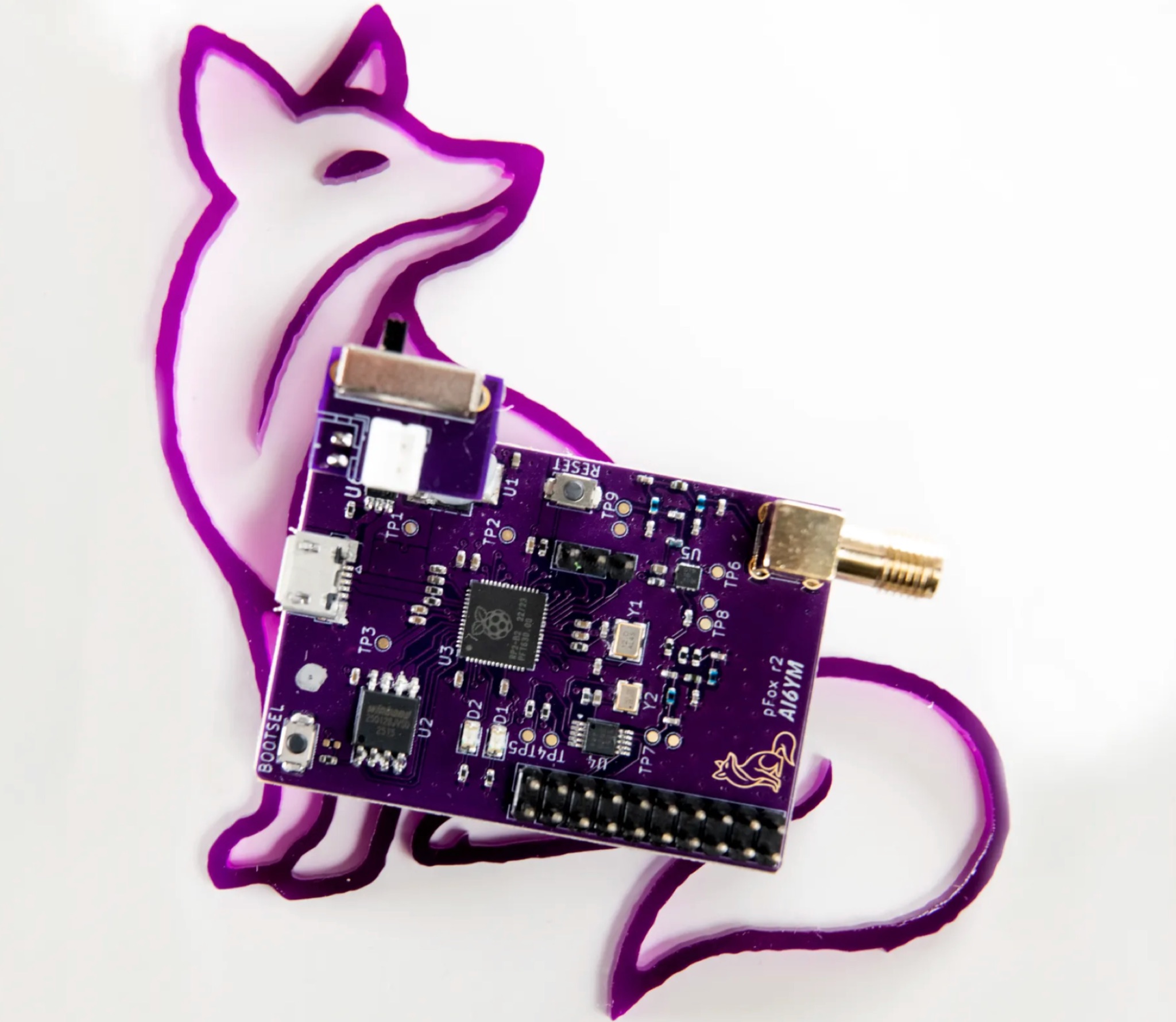 The PicoFox is a versatile fox transmitter for 2-meter ham radio operators, built around the RP2040 microcontroller. With open-source hardware and software, it can be customized to suit your needs, from APRS to other digital modes. This fully assembled transmitter comes with a rechargeable battery and antenna, ready for use. The design allows for easy addition of features like sensors or interactivity. Modulation is handled in software for smooth FM output, with ample CPU, flash, and GPIO available. Configure your PicoFox by connecting it to a computer via USB and adjusting settings in a text file. Explore the possibilities of this innovative transmitter for your amateur radio projects.
 -
 This article details the development of an 80-meter antenna within the confines of a restrictive covenant community. Faced with limited space, the author explores various options before implementing a clever hybrid design: a short 30-foot vertical wire running discreetly down the building's exterior combined with a capacitive top hat installed in the attic. Computer modeling confirmed the superiority of capacitive loading over inductive loading, increasing radiation resistance from 6 to 14 ohms. The perimeter wire top hat, naturally supported by the attic structure, resonates effectively at 3.5 MHz. The system is completed with four buried 60-foot radials installed "after dark" to maintain compliance with community restrictions.
 -
 The resource details the construction of a 433 MHz LoRa APRS iGate and a tracker, both built around _TTGO T-Beam v1.1_ microcontroller boards. Each board integrates an OLED screen, WiFi, GPS, and an SMA antenna connector, powered by an 18650 3.7 V lithium-ion battery or microUSB. The iGate operates on 433.775 MHz, with its status verifiable on aprs.fi, demonstrating practical implementation of LoRa-based APRS solutions. The methodology involves programming the modules using Visual Studio Code with the PlatformIO plugin. This process loads the necessary firmware and a JSON configuration file, which includes the operator's callsign and WiFi credentials for the iGate. The guide emphasizes the ease of programming and provides specific steps for configuration. Initial testing of the iGate and tracker, including smart beaconing configuration, is documented. The low power output of approximately 200 mW from the LoRa board's transmitter is noted, with suggestions for range extension through improved antennas or RF amplification. The author, N4MI, plans to deploy a higher-gain 70cm antenna for the iGate.
 -
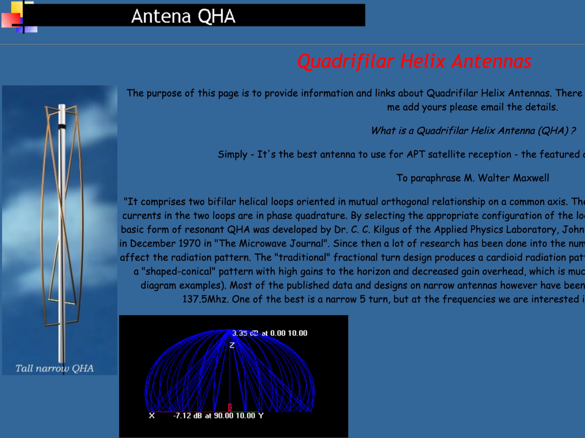 This page provides information and links about Quadrifilar Helix Antennas, the best antenna for APT satellite reception. It explains the basic design and configuration of QHA, including the research and developments that have been made over the years. The page offers insights into the radiation patterns and benefits of using QHA for APT ground stations, with examples of polar diagrams. If you are interested in learning more about QHA and its applications, this page is a valuable resource.
 -
 With increased ES propagation, this lightweight 5-element LFA antenna offers enhanced performance over the Bigwheel antenna's 5dBi gain, delivering approximately 11dBi and forward gain. Designed from G0KSC’s specifications, the 1.8m antenna was adapted for reduced weight using 6mm and 4mm rods instead of heavier tubes. 3D-printed PETG clamps ensure durability and precision, while the first tests showed excellent SWR and element coupling. Though built with a temporary Choke BalUn, the results were promising, with a Pawsey Stub BalUn planned next for further optimization.
 -
 Chavdar Levkov, LZ1AQ, presents an experimental comparison of small wideband magnetic loops, building on his previous work on wideband active small magnetic loop antennas. His research focuses on increasing loop sensitivity by maximizing the short-circuit current, which is directly tied to the "loop factor" M = A/L, where A is the equivalent loop area and L is its inductance. Levkov's methodology involves reducing inductance and increasing area through parallel or coplanar crossed (CC) configurations, comparing these designs against a reference single quad loop of 1 m2 area. Experimental verification included testing three distinct loop types: a simple quad loop, two coplanar crossed (CC) loops, and eight parallel loops, all designed to have a total geometric area of 1 m2. Measurements were conducted at 1.8, 3.5, 7, and 10 MHz using a small transmitter 270 meters away, with a Perseus direct sampling receiver for precise signal level assessment. The results consistently showed that CC loops, particularly Loop 5 (two CC circular loops with 1.44 m2 total area), yielded significantly higher currents, up to 9.1 dB over the reference loop at 3.5 MHz, validating M as a reliable predictor of loop sensitivity. Numerical simulations using MMANA further corroborated the experimental findings, demonstrating an almost perfect correlation between the calculated M factor and the induced loop current for 15 different loop models. Levkov concludes that CC loops offer superior sensitivity for a given loop area, while parallel loops are advantageous for minimizing physical volume. Practical recommendations suggest using loops with an M factor greater than 0.5 uA/pT for quiet rural environments, and he provides a spreadsheet tool, WLoop_calc.xls, to aid in optimizing loop configurations for specific operational needs.
 -
 Volda is specialized in telecom tower antenna line accessories such as cable hangers, coaxial jumpers, grounding buss bar kits, pole clamps.
 -
 This project details the development of a modular direct conversion (DC) receiver designed for experimental flexibility in amateur radio and HF signal listening. The mainframe integrates a diplexer, DBM, and AF amplifier, supporting interchangeable local oscillator and antenna filtering setups. A tunable passive HF preselector complements QRP Labs bandpass filters for enhanced signal reception. Utilizing a NanoVNA for precise tuning, the receiver achieves improved signal-to-noise ratios across amateur and non-amateur bands, making it a versatile platform for further RF experimentation.
 -
 The F6AOJ RX splitter project was created to split the antenna signal from an LZ1AQ receive loop to multiple receivers, such as radios or SDRs. The design is simple to build and effective. The splitter, mounted on the back of the LZ1AQ control board, provides two outputs—one for an Afedri SDR and another for a K3 transceiver. Measurements show a damping of -3.01 dB at 1 MHz and -3.10 dB at 30 MHz, with a low SWR (max 1.07 at 30 MHz and 1.4 at 60 MHz).
 -
 Integrating a _Software Defined Radio_ (SDR) into an existing ham radio setup involves connecting it with a standard transceiver (TRX), power amplifier (PA), and antennas. The core component is a splitter box that facilitates the connection between the TRX and the SDR, allowing for simultaneous operation without modifying existing equipment. In receive mode, the splitter ties the antenna inputs of both the TRX and a direct conversion receiver (DC RX) together. During transmission, the DC RX input is grounded via a fast telecom relay controlled by the transceiver's -SEND signal, incorporating a 10ms delay for safety. The splitter box includes a 3.7 dB input attenuator for impedance matching and acts as a protective fuse for the DC RX input. Ground loops are mitigated using common mode balun transformers, while the DC RX input is insulated with a broadband transformer. An audio switch box complements the setup, enabling users to listen to either the main transceiver, the SDR output, or both simultaneously. This configuration ensures noise immunity and safety, with the splitter housed in a screened box made from PCB material. On-air tests, such as the CQ WW 160m CW DX Contest, demonstrate the system's effectiveness, showcasing the SDR's ability to handle crowded band conditions with superior selectivity and dynamic range. The SDR's narrow bandwidth filters and waterfall display provide significant advantages, allowing operators to detect weak signals amidst strong interference. The integration of SDR with conventional radios offers enhanced operational flexibility and performance in challenging environments.
 -
 A small Yagi antenna for camper van. It is made of aluminum tubing, breaks down for storage, and works well for communicating with others. He built it in an afternoon and it gets good signal. The antenna is lightweight and can be packed up to fit inside his van while traveling
 -
 The Acom 1500 HF+6M Linear Amplifier is a high-quality and user-friendly amplifier that provides excellent performance and reliability. G6NHU, who previously owned an Acom 1000, upgraded to the Acom 1500 after nine years and has been using it for about eighteen months. Key features highlighted include the ability to connect three antennas internally, straightforward tuning process, robust construction that can handle high SWR, quiet operation, fast and quiet switching for efficient CW operation, and clean output signal even when driven hard. G6NHU highly recommends the Acom 1500 and states they would not hesitate to purchase another one in the future.
 -
 The Aziloop DF-72 antenna system provides 72 K9AY headings and 36 loop axes, allowing for rapid switching in 60 ms. It integrates a switchable 18 dB preamp, a 4-step attenuator (0-18 dB), and four 7-pole preselection filters to optimize receiver performance. The K9AY load is adjustable from 250 Ohm to 950 Ohm in 50 Ohm increments, offering flexibility for various receiving conditions. Control is managed via an intuitive Windows UI, supporting Local, Client, or Server modes, with headless remote operation possible through the built-in Ethernet Server. _Omni-Rig_ support facilitates auto-filter selection, PTT muting, and Rig-Sync functionality, enhancing integration with existing station setups. Designed by _GW4GTE_, the system utilizes a low visual impact, small-footprint antenna with orthogonal loops and an earth connection. It is suitable for general monitoring, co-channel station resolution, basic direction finding, and interference reduction across the VLF to HF spectrum.
 -
 Presents DJ5IL's personal amateur radio station, detailing his journey as a licensed operator since 1973. The resource covers his **shack setup**, including an Elecraft K4D, Icom IC-7610, and various vintage transceivers like the Drake 2-B, along with a SPE Expert 1K-FA amplifier. Antenna systems include a PRO.SIS.TEL RD1524T rotary dipole for 40/20/15/10m at 15m height, an 18m vertical dipole with an SGC SG-230 tuner for 3.5-30 MHz, and an inverted-V dipole for 80m. The site features a **QSL gallery** showcasing his custom card designs and outlines his QSL policy, emphasizing the exchange of unique, personalized cards over generic confirmations. It also includes a detailed operator's biography, tracing his early fascination with radio, obtaining his license at 16, and memorable QSOs, such as a contact with his blood-relative W3NZ. The resource also delves into the historical significance of amateur radio's role in pioneering shortwave communication following the 1912 International Radiotelegraph Convention, which initially relegated amateurs to wavelengths of 200 meters and shorter. DJ5IL's philosophy on "ham spirit" is discussed, stressing the unpolitical nature of amateur radio as a global fraternity.
 -
 HamParts produces and sell remote control accessories for ham radio operators, including antenna switch controllers and stack match controllers. Remotius 64, K9AY/4-WAY Antenna Switch Controller Easy Controller series, Lora devices, and many more ham shack accessories.
 -
 This article explores the powerful features of AutoEZ as an Excel application working with EZNEC antenna modeling software. The article demonstrates how variables, equations, and formulas enable versatile antenna design and automatic optimization. Through practical examples including dipoles, inverted vees, delta loops, and monopoles, the author shows techniques for achieving resonance, implementing transmission line resonators for broadbanding, and optimizing antennas across frequency ranges. The step-by-step demonstrations cover unit conversion, coordinate calculations, segmentation considerations, and SWR optimization. This practical guide illustrates how AutoEZ extends EZNEC's capabilities, making complex antenna modeling more efficient and accessible.
 -
 The 2m 7 element Yagi antenna is a perfect beam antenna with 11dB gain and a front-to-back ratio of 20-25 dB. It has seven elements and requires a matching network built of 3/8" aluminum tubing and RG-8 cable. The gamma tube is adjusted to provide the best fit, and the gamma-driven element feeding clamp is tightened. If the beam is vertical, a non-conducting mast is utilized to prevent detuning and skewing of the radiation pattern. For optimal VHF operating, the antenna is installed at a height of 30 feet or higher.
 -
 The TY0RU DXpedition to Benin in 2022 achieved over **100,000 QSOs** from Cotonou, IOTA AF-051, operating across 160m through 6m bands using CW, SSB, and FT8 modes. The operation involved a team of 12 operators, including _F5RAV_, _F4WBN_, and _F1TCV_, utilizing multiple stations with transceivers like the Icom IC-7300 and IC-7610, paired with amplifiers and various antennas such as verticals, dipoles, and a 4-square array for 40m. The expedition's log is available on Club Log, supporting OQRS for both direct and bureau QSLs, with F5RAV serving as the QSL manager. The site details the team's travel, setup, and operational challenges, including local conditions and equipment deployment, offering insights into the logistical complexities of activating a rare DXCC entity. Donors are acknowledged, and a photo gallery documents the activity.
 -
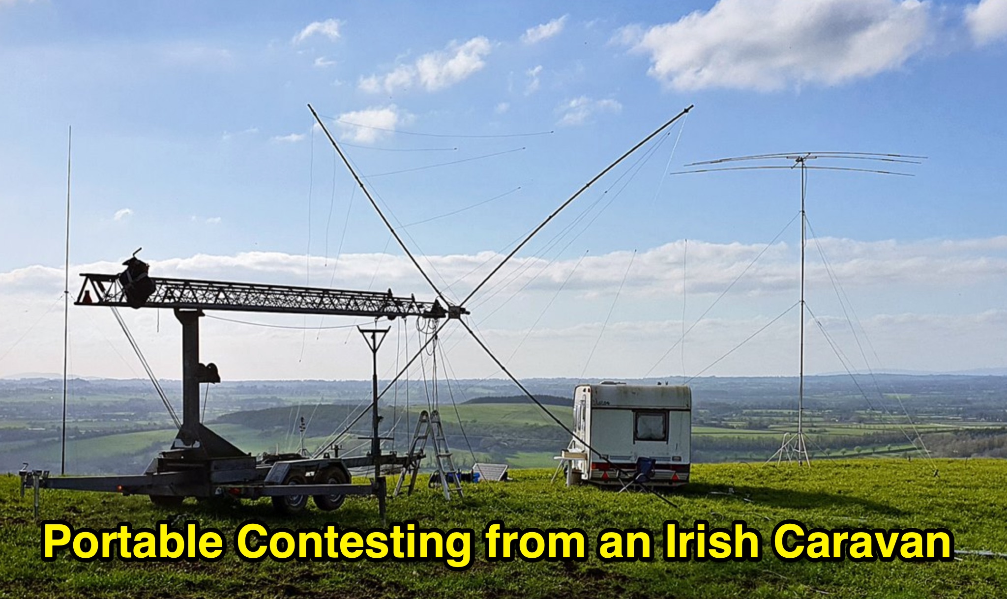 This blog chronicles over a decade of portable HF contesting from rural Ireland (2008–2019) by Olivier, operating under callsigns EI/ON4EI, EI8GQB, EI1A, and EI7T. Using only green energy from a caravan, he achieved top-tier results in major international contests—including 1st World in the 2018 IARU HF Championship (SSB LP) and multiple 1st-place finishes in CQ WW and CQ WPX SSB Europe. Operating in the demanding Single Operator All Band Low Power and SO2R categories, he deployed up to five antennas across five bands, often in remote or emergency-style conditions. The narrative blends technical detail, fieldcraft, and personal reflection, documenting triumphs, setbacks (including carbon monoxide poisoning), and the logistical challenges of sustainable portable operation—culminating in his decision to transition to team-based contesting and future DXpeditions.
 -
 This article explores the role of velocity factor (VF) in calculating stub lengths for VHF/UHF Baluns. It clarifies misconceptions about VF's relevance, distinguishing between coaxial cable interior fields and external stub fields. Practical examples, such as the Pawsey Stub and Coaxial Cable Balun, are analyzed alongside experimental findings. The results reveal that traditional VF adjustments are unnecessary for stubs with external fields but critical for internal coaxial applications. Historical and theoretical insights provide a comprehensive perspective for antenna enthusiasts and designers.
 -
 This resource presents a non-rigorous evaluation of the front-to-back (F/B) ratio of short Beverage antennas, specifically designed for low-band operation on frequencies such as 160, 80, 40, and 30 meters. The author, VE1ZAC, details the methodology used to measure the F/B ratio, which involves using a Millen Grid Dip Oscillator as a portable signal source. Measurements were taken by switching the antenna direction and recording S Meter and preamp readings to derive gain numbers. The document discusses the challenges faced in achieving accurate measurements and the assumptions made during the process, such as the calibration of S Meter units at 6 dB. This evaluation is particularly relevant for amateur radio operators interested in antenna performance on low bands.
 -
 _Icom_, _Yaesu_, and _MFJ_ are among the renowned brands available at R&L Electronics, a dedicated store for amateur radio enthusiasts. The store provides a diverse selection of equipment, catering to both novice and seasoned operators. From amplifiers and preamps to antennas and tuners, the store ensures a comprehensive inventory to meet various operational needs. Customers can also find essential components like cables, coax, and connectors, crucial for setting up and maintaining effective radio stations. In addition to new equipment, R&L Electronics offers used items, providing budget-friendly options without compromising on quality. The store's inventory includes test equipment and tools, vital for troubleshooting and optimizing radio performance. Tower components are also available, supporting those involved in more advanced setups. The website facilitates easy access to product information, shipping details, and order tracking, enhancing the shopping experience. R&L Electronics stands out by offering a variety of products that cater to different preferences and budgets, ensuring that every amateur radio operator can find the necessary equipment to enhance their setup.
 -
 The Gemini Amplifier Remote Control software operates on Windows 7 and above, facilitating remote management of the Gemini HF-1K and DX-1200 amplifiers. Users connect via Ethernet, configuring the amplifier's IP address through the front panel. The software allows seamless band and antenna selection, saving settings for each band without requiring transmission. Integration with _OmniRig_ from Afreet Software, Inc. enables automatic band adjustments based on the radio's frequency changes. Users can configure serial or virtual serial connections, with tracking options accessible through the ribbon bar. The software supports speech functionality, enhancing accessibility for operators. Firmware updates, such as version 2.5Ee, introduce features like background datalogging and power output control, uploaded via FTP. Version 1.2.0 allows users to offload internal parameter data for support purposes. The firmware upload process requires the amplifier's IP address and port 21, taking approximately 90 seconds. Users are encouraged to upgrade to the latest firmware for improved performance and remote diagnostics.
 -
 Details the construction and performance of a phase-controlled receiving array, specifically a **MicroSWA** variant, optimized for QRP low band fox hunting on 40M and 80M. The resource documents the author's iterative design process, addressing significant regional noise challenges encountered during 0100-0230 UTC fox hunt periods. Initial experiments involved a director wire on a 40M vertical, yielding limited improvement, prompting a shift towards advanced null-steering techniques. The project leverages concepts from Victor Misek’s "The Beverage Antenna Handbook" and Dallas Lankford’s extensive work on phased receiving antennas for urban lots. A key modification involved integrating a new passive phase control box and a push-pull **Norton common base preamp** using 2N5109 transistors, designed for high third-order intercept performance to maintain weak signal integrity amidst strong adjacent signals. The system incorporates Faraday-shielded transformers with RG174 primaries on -75 ferrite cores, housed in ABS plastic pipe. Performance tests confirmed the MicroSWA's ability to produce deep, steerable nulls, achieving approximately 30 dB noise reduction on 160M, 80M, and 40M. This enabled detection of QRP signals undetectable on conventional transmit antennas. The final unit includes front panel controls, a 10-11 dB preamp, and a robust power conditioner, demonstrating effective noise mitigation for challenging low band QRP operations.
 -
 Read about a ham radio operator's experience activating a POTA site at the Folk Art Center using the Chameleon MPAS Lite vertical antenna and the Chameleon Universal Clamp Mount (CHA UCM). Discover how the author carefully deploys antennas to avoid interference with other park visitors and learn about the features of the CHA UCM, a simple antenna clamp mount. Follow along as the author shares their setup and operating spot choices to maximize their portable radio experience while enjoying the peaceful surroundings of the Blue Ridge Parkway.
 -
 Early 20th-century transatlantic wireless communication efforts involved distinct technical approaches by Reginald Fessenden and Guglielmo Marconi. Marconi's systems, operational until approximately 1912, primarily utilized _spark technology_ for wireless telegraphy, facilitating Morse code communication between ships and across oceans. His Poldhu station in December 1901 radiated signals in the MF band around 850 kHz, later evolving to 272 kHz in October 1902, and eventually 45 kHz by late 1907 with increasingly larger antenna structures like the pyramidal monopole and capacitive top-loaded arrays. Fessenden, conversely, focused on _continuous wave transmission_ for wireless telephony, recognizing its necessity for speech. His transatlantic experiments in 1906 employed synchronous rotary-spark-gap transmitters and 420-foot umbrella top-loaded antennas at Brant Rock, MA, and Machrihanish, Scotland, tuned to approximately 80 kHz. Fessenden later utilized the _Alexanderson HF alternator_ at 75 kHz by late 1906 for pure CW transmission, integrating a carbon microphone for amplitude modulation. Receiver technology also differed, with Marconi initially relying on untuned coherer-type detectors, later developing the magnetic detector in 1902, while Fessenden's CW approach necessitated more advanced detection methods.
 -
 Demonstrates the construction of an active loop converter specifically designed for the Low Frequency (LF) bands, addressing common localized noise interference in LF reception. The design integrates a sharply tuned circuit and a tuned loop antenna, utilizing the loop as the sole tuned inductive element. By applying positive feedback, the converter significantly increases the loop's effective Q, achieving factors between 1000 and 2000, which sharpens tuning and reduces noise. The circuit employs an _NE602_ mixer stage, feeding its output to an HF receiver, with a crystal-locked local oscillator at 4 MHz. A 20-turn, 0.8-meter square loop antenna with 500 uH inductance is detailed, connected via 2 meters of figure 8 flex cable. The converter offers three selectable frequency bands: 195-490 kHz, 150-220 kHz (including the New Zealand amateur band), and 128-160 kHz (covering the European amateur band). Performance measurements indicate an effective 3dB bandwidth of approximately 100 to 200 hertz at 200 kHz. The article provides insights into component selection, including an _LF353_ op-amp and a trifilar wound transformer on a ferrite core. Sensitivity figures are presented, showing 7.5 uV of converted output per 1 uV/meter signal strength into a 50-ohm load, or 37.5 uV into an _FRG7_ receiver, highlighting its capability to extract weak signals from noise.
 -
 This page provides a detailed example of the modeling and analysis of an 80m delta dipole antenna with a 600-ohm bifilar feedline. The model is based on antennas used by the RAF from 1940 to 1970. It covers the original model specifications, conductor mass calculations, resonance frequency observation, geometry adjustment steps, and final antenna dimensions. The content includes theoretical formulas, resonance frequency calculations, and practical steps for adjusting the antenna for optimal performance. Overall, it serves as a practical guide for hams looking to understand and optimize the performance of a delta dipole antenna for the 80m band.
 -
 The W6PQL 23cm Beacon Project describes a **1296 MHz** beacon designed for microwave propagation studies and equipment testing, capable of 30 watts output. It utilizes a PIC 16F628A microcontroller to generate CW and FSK keying for a crystal oscillator, followed by a series of frequency doublers and triplers to reach the target frequency. The final power amplification stage employs a Mitsubishi M57762 module, providing a robust 10-watt RF output. The design emphasizes stability and reliability for continuous operation, with the microcontroller code, written in assembly, provided for customization of the beacon's callsign and message. Originally located in CM97am and aimed at 140 true, the beacon used four 4-foot Yagis stacked vertically for a total ERP of 3kW. The article includes schematics, parts lists, and construction notes to guide builders, along with antenna pattern measurements. Although the beacon itself is no longer in service as of August 2010, the detailed documentation remains a valuable reference for amateur radio operators interested in building similar **microwave** projects or understanding beacon operation.