Search results
Query: antenna construction
Links: 363 | Categories: 34
Categories
- Antennas > 20M > 20 meter Dipole Antennas
- Antennas > 20M > 20 meter Vertical Antennas
- Antennas > 40M > 40 meter Dipole Antennas
- Antennas > 40M > 40 meter Loop Antennas
- Antennas > 40M > 40 meter Magnetic Loop Antennas
- Antennas > 40M > 40 meter Vertical Antennas
- Antennas > 6M > 6 meter Moxon Antennas
- Antennas > 6M > 6 meter Yagi Antennas
- Antennas > Antenna Books
- Technical Reference > Antenna Switch
- Antennas > End-Fed > End Fed Half Wave Antenna
- Antennas > 15M
- Antennas > 17M
- Antennas > 20M
- Antennas > 23cm
- Antennas > 30M
- Antennas > Baluns > 4 to 1 balun
- Antennas > 40M
- Antennas > 70cm
- Antennas > C-Pole
- Antennas > Coils
- Antennas > Dipole
- Antennas > Receiving > EWE
- Operating Modes > GPS
- Antennas > Halo
- Antennas > Longwave
- Antennas > Masts and mounts
- Antennas > Morgain
- Antennas > Resonant Feedline Dipole
- Antennas > Slot
-
 Over 1,000 stations in approximately 60 countries were worked using this modified twin-lead folded dipole, demonstrating its effectiveness with just 4 watts on 20 meters. This design, adapted from an ARRL Handbook concept, eliminates the shorting strap found in traditional folded dipoles, simplifying construction while maintaining performance. It utilizes readily available 300-ohm TV antenna feeder ribbon, making it a cost-effective solution for radio amateurs. The antenna's robust construction allows it to handle up to 100 watts without issues, even without a **balun**. The inclusion of a variable trimmer capacitor at the stub provides flexibility for tuning across different frequencies within a band, a practical feature for operators using transceivers like the Icom 735. Formulas are provided to calculate the precise dimensions for any desired operating frequency, enabling customization for various **HF bands**.
 -
 Alan yates vk2zay's ham radio website, homebrew construction, general electronics, high voltage experiments, amateur rocketry, and general geek stuff
 -
 This document details the design and construction of a Vinecom 6N4 dual-band Yagi antenna for the 50MHz (6-meter) and 70MHz (4-meter) amateur radio bands. The antenna features 9 total elements (4 elements for 50MHz, 5 elements for 70MHz) on a 4.236-meter aluminum boom. Computer simulations using MMANA software predict 7.21 dBd gain on both bands with front-to-back ratios of 16.01dB (6m) and 15.37dB (4m). The design uses 12.7mm diameter elements mounted on a 32mm square boom, weighing 5.7kg total. Practical measurements with an MFJ-269 analyzer confirmed good SWR performance across both bands after element length adjustments.
 -
 The document provides a comprehensive overview of baluns, which are devices used to connect balanced loads, like dipole antennas, to unbalanced inputs, such as coaxial cables. It covers various types of baluns, including voltage and current baluns, and their design, construction, and testing. The text discusses the importance of baluns in preventing RF currents on coax shields and their applications in Ham radio setups. It also includes practical advice on selecting and using baluns based on antenna impedance and power ratings, along with detailed performance evaluations and construction tips for different balun configurations.
 -
 Adventures in amplified GPS antenna construction; an experiment
 -
 The G5RV multiband HF antenna, designed by Louis Varney (G5RV) in 1946, is a popular compromise antenna offering good overall performance on most HF bands when paired with an external antenna tuner. The basic full-size G5RV measures 102 feet across the top for 80 through 10 meter operation and is fed at the center via a 34-foot low-loss feed-stub. This interaction between the radiating section and the feed-stub facilitates matching across 80-10 meters with a standard tuner, often eliminating the need for ladder line directly to the shack. The antenna's design center frequency is 14.150 MHz, configured as a 3/2-wave dipole on 20 meters, with its 102-foot length derived from long-wire antenna formulas. Construction details emphasize the matching section, which can be open wire, ladder line (window-type), or TV twin lead. Each type has a specific velocity factor (VF) affecting its physical length for an electrical half-wave on 14 MHz; for instance, open wire requires 33.7 feet (VF 0.97), ladder line 31.3 feet (VF 0.90), and TV twin lead 28.5 feet (VF 0.82). The article provides formulas for calculating these lengths and discusses the antenna's behavior on individual bands, from 3.5 MHz where it acts as a shortened dipole, to 28 MHz where it functions as two three-half-wave long-wire antennas fed in-phase. Practical construction notes include recommendations for vertical descent of the matching section, sealing the coax junction, providing strain relief, and winding a coaxial choke coil to mitigate common mode current. The resource also presents dimensions for double-size (204 ft) and half-size (51 ft) G5RV versions, along with their corresponding matching section lengths for various line types, making it a versatile reference for hams considering this classic wire antenna.
 -
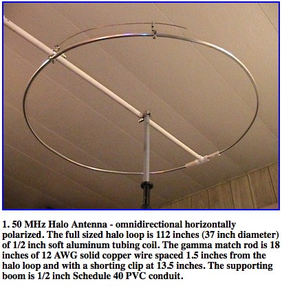 A well documented article about construction and analysis of a horizontally polarized halo antenna for 6 meters band by Dr. Carol F. Milazzo, KP4MD
 -
 A 50-ohm 10W resistor forms the core of this portable QRP antenna, designed by _K0EMT_ for convenient operation on 160m and 80m. The construction involves soldering the resistor to a BNC connector, with one lead to ground and the other to the center conductor, then insulating the assembly. This minimalist design aims to provide a highly portable solution for low-band QRP operations, acknowledging the inherent trade-offs between antenna size and efficiency. Testing with an antenna analyzer revealed low SWR on both 160m and 80m, with a Yaesu FT-817 confirming good matching. While 40m and 30m showed higher SWR, the primary focus remains on the lower bands. The author successfully tested the antenna with **2.5W CW** output, demonstrating its practical application for QRP field operations where ease of deployment is paramount, even if it means sacrificing some **gain** compared to full-sized antennas.
 -
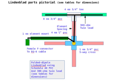 This document contains the detailed instructions to build a homemade lindenblad antenna using a twin-lead as dipole elements. This document contains 9 pages and includes a detailed construction sequence and some drawings to build this antenna for UHF and VHF ham radio bands
 -
 The utility "NEC-2 for MMANA" is intended for calculation of antenna models made and optimized in program MMANA and for construction and simulation of antenna models using input language NEC-2 and based on MMANA models.
 -
 Rotator controller, azimuth & elevation control of rotators (automatic antenna turning) based on commands from computer. A project by Pavel VACHAL and OK1DX - KF9VM
 -

-
 The Resonant Feedline Dipole (RFD) HF antenna design utilizes a single piece of coaxial cable and a stranded wire section, forming a 1/4-wavelength radiator. This configuration, based on a 1997 ARRL Handbook design (page 20.17), functions by RF traveling on the inside of the coax shield and returning on the outside, creating the second half of the dipole. A choke wound into the feedline prevents RF current from flowing back down the feedline. Construction details include using RG-58a/u coax for a 75m version, with a 1/4-wavelength section of stranded wire soldered to the center conductor. The document provides choke dimensions for RG-213, RG-8, and RG-58 coax across 3.5 MHz to 28 MHz, specifying cable length and number of turns. Dipole dimensions are also tabulated for frequencies from 3.6 MHz to 28.4 MHz, listing overall length and individual leg lengths. Field tests included deployment near Bryson City at 5 feet off the ground and as a sloper during WCARS Field Day in Asheville, yielding successful local and regional contacts.
 -
 Optimizing a G5RV or ZS6BKW multiband wire antenna for HF operation often involves addressing common SWR issues and understanding feedline characteristics. This resource chronicles the construction and performance evaluation of a G5RV, initially built for 80m, 40m, 15m, and 10m bands, by a newly licensed Foundation operator. The author details the selection of materials, including 3.5 mm stainless steel wire for the doublet arms and enameled copper wire for the open-wire feeder, and the initial decision to omit a balun based on common online information. The narrative highlights the initial disappointing performance, characterized by high receive noise and poor signal reports on 80 meters, despite the transceiver's internal ATU achieving a 1:1 match. This led to experimentation with a coax current balun and further research into G5RV myths, such as SWR claims and the necessity of a balun. The author then describes modifying the antenna to the ZS6BKW configuration, which involves specific changes to the doublet and feedline lengths, and integrating a 1:1 current balun wound on a ferrite toroid. The modifications resulted in improved reception and transmit performance across the bands.
 -
 The NCDXF/IARU International Beacon Project operates a worldwide network of 18 high-frequency radio beacons, continuously transmitting on 14.100, 18.110, 21.150, 24.930, and 28.200 MHz. These beacons, initially launched in 1979 with a single station and expanded to the current 18-beacon system in 1995, provide reliable signals for both amateur and commercial users to assess current **ionospheric propagation** conditions. The system's design, construction, and operation are managed by volunteers, covering hardware and shipping costs. The resource details the evolution of the beacon network, including the transition from Kenwood TS-50s transmitters to Icom IC-7200 radios with a new controller design implemented in 2015. It explains how listening for these 100-watt signals, transmitted to vertical antennas, allows operators to determine band openings and optimal propagation paths globally. The content also references three QST articles providing historical context and technical specifics of the beacon project. Practical information includes methods for identifying transmitting beacons via a schedule or specialized software like FAROS and Skimmer, which integrates with the **Reverse Beacon Network** for automated monitoring.
 -
 Demonstrates the construction of a 144 MHz turnstile antenna, detailing its design for omnidirectional, horizontally polarized VHF operation. The resource outlines the physical dimensions and materials required, including specific lengths for the radiating elements and the use of _RG-58_ coaxial cable for phasing. It covers the assembly process, emphasizing the critical spacing and connection points to achieve the desired radiation pattern and impedance matching for the _2-meter band_. The article presents measured _SWR_ performance across the 144-146 MHz segment, showing a low SWR of 1.2:1 at 144.5 MHz, which is suitable for general VHF use. It compares the turnstile's performance to a 9-element Yagi, noting the turnstile's advantage in providing consistent signal strength from all directions without requiring a rotator. Practical application for local FM simplex and repeater operations is implied, offering a simple yet effective antenna solution for fixed or portable stations.
 -
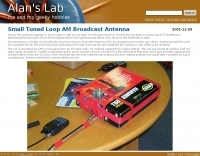
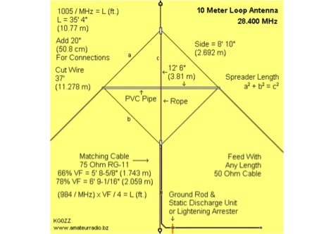 A nice loop antenna project for 28 MHz with schematic diagram, construction details and a complete video instruction
 -
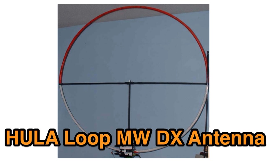 An excellently presented article on the design and construction of a medium wave DX Antenna
 -
 One point eight MHz to 30 MHz is the operational bandwidth for this 4:1 Ruthroff voltage balun, designed to interface an unbalanced T-Match network with a balanced antenna system. The project details the construction using a _T200-2_ powdered iron toroid core, tightly wrapped in PVC electrical tape for insulation, and wound with 17 double bifilar turns of 1.25mm enamelled copper wire. This outboard balun offers flexibility, allowing hams to trial various baluns based on antenna system and impedance characteristics, rather than integrating it directly into the tuner. The resource includes a schematic of the balun, a wiring diagram showing winding connections, and a table suggesting alternative toroid cores like the T80-2 or T400-2 with corresponding winding counts. Component sourcing is straightforward, listing items such as the _Amidon_ T-200-2 core, SO-239 connector, and a sealed polycarbonate enclosure from Jaycar. Performance evaluation was conducted using an _AIM 4170C_ antenna analyser, demonstrating efficient 1:4 voltage transformation across the specified HF spectrum. Further efficiency tests involved measuring RF power loss at various frequencies, revealing minimal loss—less than 0.7 dB from 3.6 MHz to 30 MHz, and only 2.0 dB at 1.8 MHz. These measurements, performed under ideal 50-ohm conditions, confirm the balun's effectiveness as a low-loss interface for multi-band antenna systems. The page also links to several other balun and unun projects, including 1:1 current and voltage baluns, and 9:1 voltage ununs, providing a broader context for impedance matching solutions.
 -
 A novel approach to contruction of a gamma match.
 -
 The resource presents a detailed schematic for constructing a dual-band vertical antenna, specifically designed for operation on the 2-meter and 70-centimeter amateur radio bands. It illustrates the physical layout, critical dimensions, and component placement necessary for successful replication. Key elements such as the radiating elements, phasing sections, and feed point are clearly depicted, providing a visual guide for radio amateurs undertaking a homebrew antenna project. The diagram specifies the lengths for the VHF and UHF sections, indicating how these elements are integrated to achieve dual-band functionality from a single coaxial feedline. It also implies the use of common materials readily available to most experimenters, focusing on simplicity and effectiveness in its design. The visual format of a GIF image ensures direct access to the construction details without requiring extensive textual interpretation. This schematic serves as a practical reference for hams interested in building a compact, efficient vertical antenna for local and regional FM communications, offering a proven design for immediate implementation.
 -
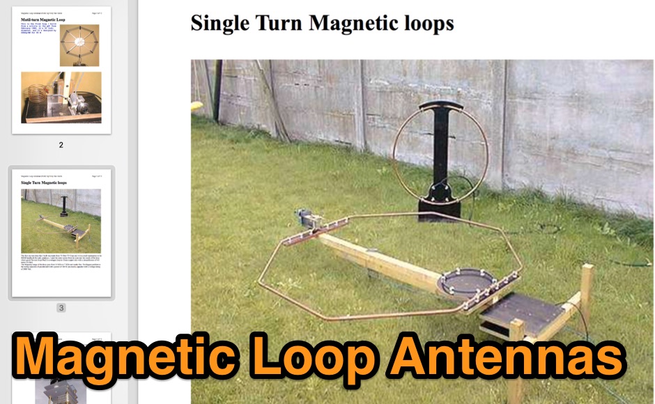 A complete guide to magnetic loop antenna construction, with analysis of multi-turn and single-turn magneti loops, and and insight on choosing the optimal capacitor, or homebrewing your own butterfly capacitor
 -
 Presents a QRP AM/CW transmitter project specifically designed for the 10-meter band, utilizing a crystal oscillator and a collector-modulated AM oscillator. The design employs a 2N2219(A) transistor in a Colpitts configuration, generating 100 to 350 mW of RF output power depending on the 9-18 Volt supply voltage and modulation depth. Frequency stability is maintained by a 28 MHz crystal, with fine-tuning possible via a Ct1 trimmer capacitor for approximately 1 kHz adjustment. The resource details the RF oscillator stage, implemented with a 2N2219 NPN transistor, emphasizing frequency stability and low power dissipation. It also covers the amplitude modulation stage, managed by a 2N2905 PNP transistor, which impresses audio information onto the carrier. Selective components (C3, C4, C7, C5) enhance voice frequencies within a +/- 5 kHz bandwidth, and modulation depth is controlled by R2 and R3. The project includes a 3-element L-type narrow bandpass filter (Ct3, L3, C10) to suppress harmonics and ensure a clean output signal. The project provides a complete schematic diagram, a comprehensive parts list including specific capacitor, resistor, and inductor values, and construction notes for the coils (L1, L2, L3). It also offers practical advice on enclosure requirements, suggesting an all-metal case or a PVC box with graphite paint for RF shielding. Operational parameters such as current draw (27mA@9V to 45mA@16V) and input impedance (50 Ohms) are specified, alongside guidance on antenna matching and the importance of a valid amateur radio license for 10-meter band operation.
 -
 The ZS6BKW multiband antenna, an optimized variant of the classic G5RV, features a 102-foot (31.1 m) horizontal span and a 39.1-foot ladder line matching section. This design, derived by G0GSF (formerly ZS6BKW) in the early 1980s using computer programs and _Smith charts_, aims for improved SWR across multiple HF bands compared to its predecessor. Construction details specify Wireman 554 ladder line and #14 AWG THHN copper wire for the radiators, with precise instructions for determining the velocity factor (VF) of the ladder line using an antenna analyzer or dip meter, ensuring accurate physical length for the matching section. The radiator length is electrically 1.35 wavelengths for the 20-meter band, requiring careful trimming during tuning. Field measurements with an _AIM-4170C_ analyzer by KI4PMI and NC4FB demonstrated good SWR curves and bandwidth on 6, 10, 12, 17, 20, and 40 meters. The antenna was deemed unusable on 15 and 30 meters due to very high SWR, but an LDG AT-100PRO autotuner successfully brought 6 and 80 meters into tune. Contacts were made on 80, 40, 20, and 17 meters, including a **17-meter** contact to Spain. EZNEC models for 80-6 meters are provided, along with an AutoEZ model by AC6LA, which predicted good SWR for 80-10 meters. W5DXP's modifications for an all-band HF ZS6BKW are also referenced.
 -
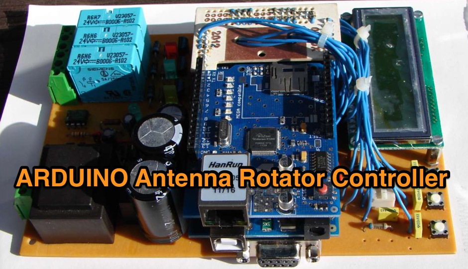 Inspired by Milan OK7GU, the goal is to build an universal antenna controller - for different types of rotor, different motor, encoder
 -
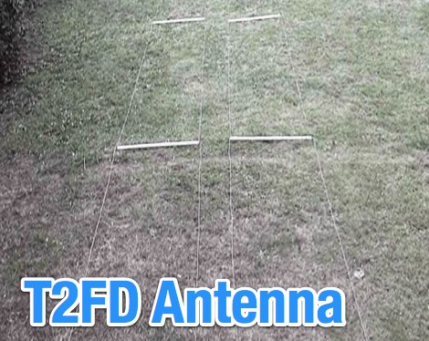 T2FD A practical construction article, which first appeared in the Electronic DX Press, contains a number of useful photos and detailed instruction to build this antenna by VK3BVW
 -
 Operating on the 2200m band (135.7-137.8 kHz) often presents challenges for amateur radio transceivers, which typically exhibit poor receiver performance at these very low frequencies. This project addresses the issue by providing a design for a dedicated 137 kHz antenna preamplifier, specifically tailored to improve signal reception for radios such as the _Yaesu FT-817_. The preamplifier circuit utilizes a low-noise FET input stage, crucial for minimizing self-generated noise and maximizing the signal-to-noise ratio from weak LF signals. The design includes a detailed schematic, component values, and construction notes, enabling homebrewers to build a functional unit. The goal is to achieve significant gain, making the faint signals on 2200m more discernible and improving overall band usability. Key design considerations include impedance matching to typical antenna systems and ensuring stable operation across the narrow LF segment. The circuit aims for a **low noise figure** and sufficient amplification to overcome the inherent limitations of general-purpose HF transceivers when operating below **200 kHz**.
 -
 Operating an 80/40/20M fan dipole for DX is analyzed through EZNEC modeling, focusing on the antenna's performance in a real-world, low-height installation. The resource details the physical construction and SWR measurements of the fan dipole, comparing them against EZNEC simulations. It also incorporates High Frequency Terrain Analysis (HFTA) data to illustrate typical DX elevation angles for various regions from New England, providing a crucial context for evaluating antenna patterns. The analysis presents EZNEC-generated azimuth and elevation patterns for each band (80M, 40M, 20M) at specific frequencies, showing gain figures at different elevation angles relevant to DX propagation. It compares the modeled SWR with measured SWR, attributing discrepancies to coax attenuation. The study concludes with observations on the antenna's azimuth performance (omnidirectional within ±1.5 dB) and its less optimal elevation gain at desired DX angles, highlighting the impact of low antenna height on DX capabilities.
 -
 Demonstrates the construction and implementation of a **two-element phased vertical array** for 40 meters, utilizing _Christman phasing_ techniques. The author, W4NFR, details the process from building individual 1/4-wave aluminum verticals to integrating them into a phased system. The resource covers antenna spacing of 32 feet, elevated radial design, and the critical steps for tuning each vertical to achieve a 1.1:1 SWR before combining them. It also provides insights into calculating precise coax lengths for feedlines and the phasing delay line, emphasizing the use of an MFJ-269 Antenna Analyzer for verification. The finished system exhibits good front-to-back nulls, with an overall SWR ranging from 1.6:1 to 2.2:1, which is managed by an antenna tuner. The project includes detailed photos of the relay box, showing 12 VDC relays capable of handling 5KV, and the control box in the shack for switching between three different antenna pattern configurations. Static bleed-off chokes are incorporated for protection, and the construction emphasizes robust weatherproofing for outdoor elements.
 -
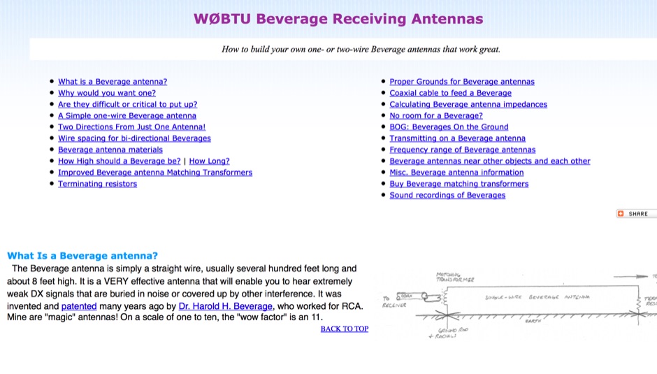 Comprehensive information page about bi-directional Beverages, including applications, construction details, and tips.
 -
 A fractional bandwidth of up to 30:1 characterizes spiral antennas, making them highly effective across a very wide frequency range, often from 1 GHz to 30 GHz. The resource details two primary types: the **Log-Periodic Spiral Antenna** and the **Archimedean Spiral Antenna**, defining each with specific polar functions and illustrating their planar configurations. It explains that spiral antennas are typically circularly polarized, with a Half-Power Beamwidth (HPBW) of approximately 70-90 degrees, and a peak radiation direction perpendicular to the spiral plane. The content elaborates on critical design parameters affecting radiation, including the total length (outer radius) for lowest frequency, the flare rate ('a' constant) for optimal radiation versus capacitive behavior, the feed structure (often an infinite balun) for high-frequency operation, and the number of turns (typically 1.5 to 3 turns). It also discusses the theoretical impedance of 188 Ohms for Log-Periodic spirals, derived from Babinet's Principle, noting actual impedances are often 100-150 Ohms. The article presents a simple construction method for an Archimedean spiral, demonstrating VSWR and efficiency measurements. Measurements from a constructed spiral antenna show a VSWR that is fairly constant across the band, albeit with a mismatch loss of about 3 dB. The antenna efficiency remains around -5 dB (31.6%) across its operating range, indicating a decent wideband radiator despite opportunities for optimization.
 -
 Demonstrates the adaptation and construction of a 7-element DK7ZB Yagi antenna for the 4-meter band (70 MHz), utilizing components from a defunct 2-meter CUE DEE Yagi. The resource details the modifications made to the original DK7ZB design to fit the shorter CUE DEE boom length, specifically adjusting element lengths for 6mm rod elements while reusing existing mounting holes for the reflector and last director. It provides precise element lengths for the reflector, dipole (12mm aluminum tube), and five directors, along with a note on cutting elements for transport. The article includes a 4NEC2 simulation file for performance analysis and an SWR plot, confirming the antenna's electrical characteristics. It also specifies the calculation for the quarter-wavelength matching cable using SAT752F coaxial cable, resulting in a 909mm length. Practical application is shown with the finished antenna in operation at JO20XC, listing several activated Maidenhead squares such as JO56PA and JP40KS, validating its effectiveness for portable 70 MHz operations.
 -
 This PDF document details the construction of a **70 MHz** Big Wheel antenna, a horizontally polarized omnidirectional array. The design utilizes three full-wave loops, each approximately **2160 mm** in diameter, arranged in a triangular configuration. The resource provides mechanical dimensions for the antenna elements and a comprehensive bill of materials, specifying component quantities and types, such as M8 stainless steel bolts, 15x15x1.5 mm square aluminum tubing for spacers, and 8 mm aluminum rod for the arcs. The central hub is constructed from two 160x160x8 mm aluminum plates, with four 40 mm long polyamide insulators supporting the radiating elements. The feed system incorporates a 50 mm diameter aluminum pipe for mounting and a matching stub constructed from a 120x20x2 mm aluminum sheet, connected via M8x10 mm bolts. The resource includes a diagram illustrating the mechanical dimensions and assembly points, including the N-connector fixing point and the center conductor attachment. The project was published on May 25, 2011, by Peter OE5MPL and Rudi OE5VRL. DXZone Focus: PDF | 70 MHz Big Wheel | Mechanical Dimensions | **2160 mm** loop diameter
 -
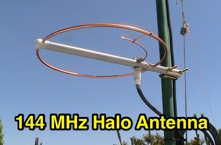 Construction and analysis of a low cost omnidirectional horizontally polarized antenna for 144 MHz, including notes on halo antenna stacking
 -
 6 Meter 1/4 Wave Antenna by Mike Fedler N6TWW. A detailed article with pictures of construction details of this 50 Mhz antenna
 -
 The ZS6BKW multi-band antenna, an optimized variant of the classic G5RV, is presented with detailed construction and tuning instructions. This resource outlines the antenna's design principles, which were developed by _Brian Austin (G0GSF)_ using computer programs and Smith charts to achieve optimal dimensions. It provides specific guidance on calculating and adjusting the lengths of the radiators (L1) and the matching ladder line (L2), emphasizing the critical role of velocity factor (VF) in achieving resonance. The article includes a step-by-step procedure for empirically determining the VF of ladder line using an antenna analyzer, ensuring accurate physical lengths for the matching section. It details the tuning process for the radiators, offering practical tips for incremental adjustments to achieve the best SWR curve. The resource presents SWR measurement results obtained with an _AIM-4170C_ analyzer across multiple bands, alongside predicted SWR graphs from an AutoEZ model. It confirms successful contacts on 80, 40, 20, and 17 meters, including a **17-meter DX contact** to Italy. EZNEC and AutoEZ models for the ZS6BKW antenna, covering 80 through 6 meters, are provided for download, allowing further analysis and customization. The document specifies component details, such as the use of Wireman 554 ladder line and #14 AWG THHN copper wire, and discusses the antenna's performance characteristics, noting high SWR on 15 and 30 meters but successful tuning on 6 and 80 meters with an external tuner.
 -
 Article by VU2GT about VHF antennas, how to evaluate performances and models.
 -
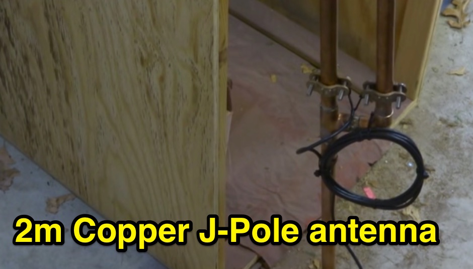 This is the construction of a copper cactus style j-pole antenna.
 -
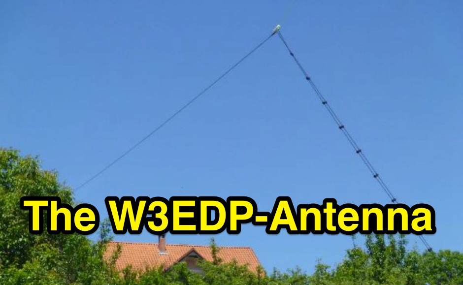 Hints for building a W3EDP-Antenna, includes the construction of the 1:4-balun by DK7ZB
 -
 Examining the _Angle of Radiation_ and its impact on amateur radio operations, the resource provides insights into optimizing antenna performance for DX and local contacts. It features a design for SPOTTO, a direct conversion high-performance universal DSB transceiver, detailing its construction and operational characteristics for homebrew enthusiasts. Additionally, the site presents a 7-element VHF high-gain antenna design, offering practical schematics and expected performance metrics for those seeking enhanced gain on VHF bands. The resource also covers the development and popularity of the _FT8_ digital mode, highlighting its effectiveness in weak-signal conditions and its role in special event operations like the FT8DMC anniversary. It includes information on Hamfest India 2023 and the Lamakaan Amateur Radio Convention, providing dates and organizational details for significant Indian amateur radio gatherings. Technical articles on Direct Digital Synthesizers (DDS) VFOs and low-cost multifunctional frequency counters offer practical project ideas for radio amateurs.
 -
 This web article by VK3BLG details the construction of an experimental 70cm (432 MHz) circularly polarized patch antenna, intended for satellite communication. The resource provides dimensions, feed point specifications, and impedance matching considerations for a single patch element, with discussion extending to array configurations for circular polarization. Construction involves a copper patch element on a dielectric substrate, fed via a coaxial cable. The design is based on information derived from AO-40 satellite antenna specifications, focusing on achieving circular polarization for satellite reception. The article includes specific dimensions for the patch and feed points, along with impedance values. Validation is implied through on-air satellite reception reports, with initial signal reports of **1 S-point above noise** for AO-40 beacons using a grid reflector, improving to **3-4 S-points above noise** with a 2-turn helical feed. The author references a _NanoVNA_ for impedance measurements and discusses the relationship between slot and dipole antennas in the context of patch design. DXZone Focus: Web Article | 70cm Patch Antenna | On-Air Satellite Reception | Circular Polarization
 -
 KA7OEI article on homebrewing Yagi UDA antennas with practical suggestions and designing notes.
 -
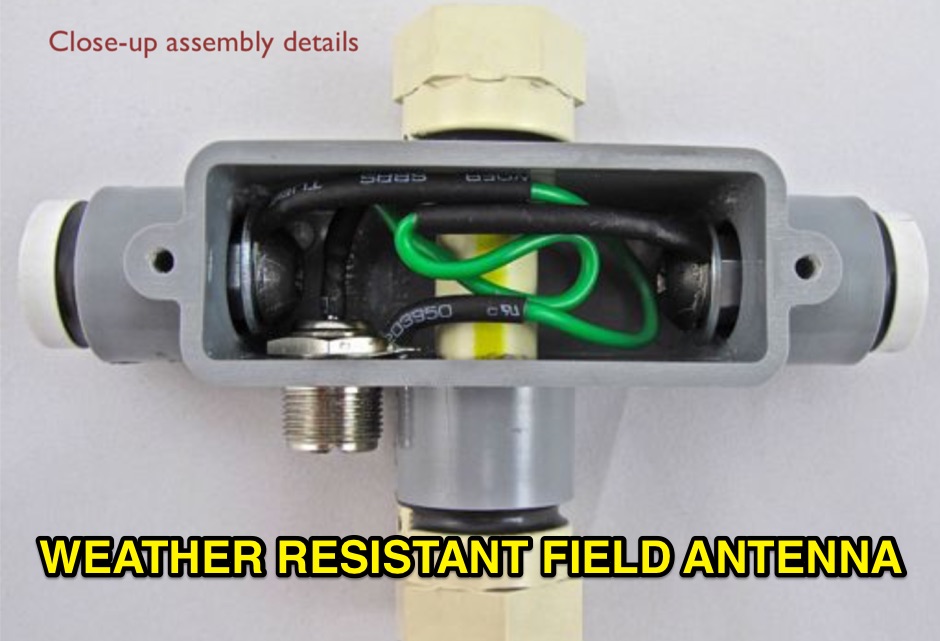 Photo construction manual of a portable antenna made with two heavy duty whips by buddipole. In this article has been implemented a 50 MHz portable dipole.
 -
-
 The resource details the construction of a multiband trap-style Inverted-V antenna designed for operation on 3.5 MHz, 7 MHz, 14 MHz, 21 MHz, and 28 MHz. It presents specific winding data for the traps, including the number of turns, wire gauge, and coil former dimensions, crucial for achieving resonance on the target bands. The document provides a parts list and a diagram illustrating the antenna's physical layout and trap placement. It outlines the process for building the traps using PVC pipe formers and specifies the required capacitor values for each trap. The design emphasizes a practical approach to achieving multiband operation with a single feedline, a common goal for HF operators with limited space. The document includes a table with antenna segment lengths for each band, allowing for precise replication of the design. It also offers insights into tuning and adjustment, ensuring the antenna performs optimally across the designated amateur radio bands.
 -
 A 38-foot Tristao Tower, similar to the U.S. Tower HDX538, was installed twice by the author, first in 1980 and then reinstalled in 1989. The resource details the challenges of self-performing heavy construction tasks like breaking concrete and digging a 3' x 3' x 6' deep footing, contrasting it with hiring professionals for the second installation. It highlights the financial and physical costs associated with DIY tower foundation work, noting a rebar cage cost of $65 in 1980 versus $150-$175 today, and the expense of tools for bending rebar. The content emphasizes the critical importance of obtaining building permits, recounting how a permit in Buena Park, California, nullified a neighbor's complaint about TVI. It also discusses the necessity of adhering to local building codes, such as the 1975 UBC and the subsequent 1985 UBC recertification requirement, which reduced the allowed antenna wind loading from 30 square feet to 20 square feet for the author's _KT34A_ Yagi. The footing depth also increased from 6 feet to 6.5 feet under the newer code. Practical advice includes hiring licensed contractors for specialized work, delaying antenna installation for a month after raising the tower, and verifying buried utilities before any excavation. The author provides specific examples of utility location services like _DigAlert_ in California, underscoring the legal and safety implications of neglecting this step. The narrative is grounded in personal experience, offering a realistic perspective on tower projects.
 -
 The **KC0KJF** personal amateur radio page provides a collection of resources for fellow hams, particularly those interested in operations within southwest Missouri. It offers detailed listings for **Missouri repeaters** on both 2 meters and 70 centimeters, serving as a practical reference for local VHF/UHF communication. The site also includes information about the operator's station setup and antenna projects, such as a dipole and a bazooka antenna, which can offer insights into basic antenna construction and deployment. Beyond local repeater data, the page features links to the FCC Part 97 rules, essential for understanding amateur radio regulations. The operator, licensed as a Technician Class since April 16, 2001, shares his journey from Citizen's Band Radio to amateur radio, driven by a lifelong fascination with shortwave listening. This narrative provides context for the resource's focus on practical operating information and foundational regulatory knowledge. Additional content covers specific equipment like the 2-meter/70-centimeter Arrow Antenna, useful for hams considering portable or fixed station VHF/UHF setups.
 -
 For radio amateurs and electronics enthusiasts requiring specialized wiring solutions, Multi/Cable Corporation provides custom multi-conductor cable manufacturing services. They focus on made-to-order constructions, offering a broad range of specialty cable products including composite, instrumentation, electronic, flexible cord, thermocouple, high-temperature, and Mil-Spec wire and cable. Their capabilities extend to extensive customization of all cable components, ensuring precise adaptation to specific application requirements, which can be critical for bespoke shack setups or antenna control lines. With over 50 years in business, Multi/Cable emphasizes low minimum orders, quick turnarounds, and competitive pricing, making custom cable solutions accessible even for smaller projects. A case study highlights their role in helping an emergency vehicle lighting company expand offerings by providing versatile and cost-effective wire bundles, demonstrating their ability to support diverse technical needs beyond typical off-the-shelf options. They also provide reference data and guides on choosing conductors, insulation, and jacketing materials.
 -
 Presents the construction of a 2-meter **Skeleton Slot Yagi** stack, detailing the design process and practical considerations for VHF operation. The author shares insights from building and testing this antenna, emphasizing its performance characteristics for local and extended range contacts. The project outlines the specific dimensions and materials used, providing a clear path for other radio amateurs to replicate or adapt the design for their own stations. The resource covers the unique aspects of the Skeleton Slot radiator, explaining how its geometry contributes to gain and pattern control. It includes discussions on impedance matching and feedline considerations crucial for optimizing power transfer and minimizing SWR. The article draws on real-world testing, offering practical results that validate the theoretical design. This project serves as a valuable reference for those interested in custom VHF antenna solutions.
 -
 The NB6Zep Antenna, an electrically shortened 80-meter end-fed wire, addresses space constraints for low-band operation by integrating two loading coils into a 37-foot wire. This design, modeled with _EZNEC_, explores configurations like the quarter-wave sloper and inverted-L, with the latter providing a more vertical radiation pattern and practical backyard deployment. The resource details specific coil construction, recommending 21 uH coils made from _BW coil stock #3026_ or similar, and outlines wire segment lengths for optimal tuning. Performance analysis indicates a radiating efficiency of approximately 27% with good ground conductivity, resulting in a signal typically 3-4 dB down compared to a full-size quarter-wave vertical. The antenna exhibits a narrow bandwidth, around 50 kHz, due to its high Q, necessitating a tuner for broader band operation. Feedpoint impedance is low, with ground resistance playing a critical role in achieving a usable SWR. The article emphasizes the importance of an effective ground rod at the feedpoint for proper operation and tuning, suggesting an antenna analyzer for precise adjustments. It confirms the antenna's suitability for DX, citing successful contacts from Oregon to the East Coast and Hawaii on a 160-meter variant, making it a viable option for urban operators seeking low-angle radiation on 80 meters.