Search results
Query: ARRL
Links: 412 | Categories: 2
-
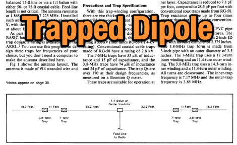 Build a space efficient trapped dipole antenna for 40-80-160 meter bands using RG-58 and PVC pipe. The document provides a brief guide on building a compact dipole antenna appropriate for the 40, 80, and 160-meter amateur radio bands. It explains the materials, building processes, and tuning methods required to provide best performance while preserving space. The paper also discusses theoretical elements of dipole antennas, such as impedance matching and feedline selection.
 -
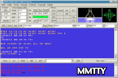 MMTTY V1.70K, released June 4, 2017, provides a full 3.5MB installation for RTTY operations on Windows platforms including XP, Vista, and Win7. The software, developed by JE3HHT, utilizes a soundcard for RTTY decoding and encoding, with support for external FSK keying via parallel or serial ports, including USB serial adapters. An MMTTY Engine V1.70K is also available, specifically designed for integration into other commercial amateur radio programs requiring RTTY functionality. Older versions such as MMTTY V1.68A (September 29, 2010) and MMTTY V1.66G are accessible, alongside a non-installer version (MMTTY168A-i.zip) for experienced users. The resource includes an updated ARRL.DX file for callsign lookup and offers a comprehensive 18MB PDF help file for offline viewing or download. Support for the software is directed to a group.io community. MMTTY integrates with **COMFSK** and **EXTFSK/EXTFSK64** for precise FSK keying, enabling direct radio control. The site also hosts MMJARTS V1.03, a 254KB utility released September 6, 2002, which generates log and summary sheets specifically for the JARTS RTTY contest, linking to the official JARTS website for contest information.
 -
 Home made vertical antenna for 80 40 15 10 meters ARRL PDF file taken from QST June 1978
 -
 This PDF article from April 2001 QST details the construction of the "NJQRP Squirt," a reduced-size 80-meter inverted-V dipole antenna. The resource provides a general construction sketch, a photograph of the assembled antenna, and specific dimensions for PC-board insulators. The antenna consists of two wire legs, each approximately **34 feet long**, separated by 90 degrees, fed at the center. It is designed for operation on 80 meters (3.5-4.0 MHz) as a quarter-wavelength antenna, requiring a low-loss feedline and an external antenna tuner due to its non-resonant feedpoint impedance. Construction utilizes readily available materials, including 1/16-inch glass-epoxy PC board for end and center insulators, and #20 or #22 insulated hookup wire for the elements. The feedline specified is 300-ohm TV flat ribbon line, with a note on potential trimming for tuner compatibility. N2CX reports the antenna's center should be elevated to at least **20 feet**, with ends no lower than seven feet above ground, resulting in a ground footprint of approximately 50 feet wide. The design prioritizes NVIS propagation for local 80-meter contacts. DXZone Focus: PDF Article | 80m Inverted-V Dipole | Construction Notes | 34 ft element length
 -
 Operating a handheld transceiver (HT) while bicycle mobile presents a significant challenge due to the lack of an effective ground plane on a bicycle frame. This project addresses that issue by providing construction details for a 2-meter antenna, specifically adapting the _ARRL Hints and Kinks_ design by Charlie Lofgren, W6JJZ, known as the "Bike 'n Hike Special." The antenna is designed to function efficiently on the 144 MHz band, offering a practical solution for portable VHF communication. The design emphasizes simplicity and portability, crucial for mobile operations where space and weight are at a premium. It details the necessary components and assembly steps, allowing amateurs to build a functional antenna that overcomes the inherent limitations of a bicycle as a radio platform. The original concept was published in the ARRL's well-regarded collection of practical amateur radio solutions. This antenna project enables bicycle mobile operators to achieve improved signal performance compared to a stock HT rubber duck, facilitating more reliable contacts while on the move. It represents a straightforward approach to enhancing VHF communications for active hams who combine cycling with their radio hobby.
 -
 calculates the dimensions and spacings of the elements needed to build a log periodic antenna, given tao, sigma and the lower and upper cutoff frequencies.
 -
 A comparison of different multi-band dipole techniques
 -
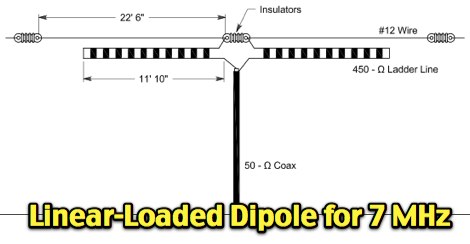 A short but efficient dipole for 40 meters band
 -
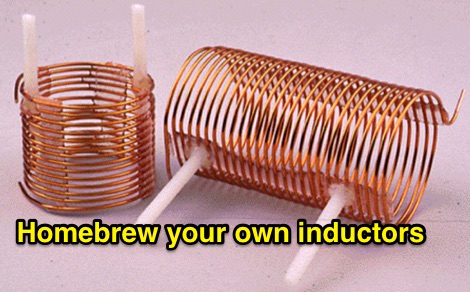 Cannot find the inductors you need for an antenna, a tuner or amplifier ? Build your own it is easy!
 -
 Suggestions on finding RF ground when you live in an apartment and you want to setup an antenna
 -
 The ARRL website provides a graphical representation of US frequency allocations for amateur radio operators. Users can download a PDF document containing the band plan and access additional information on frequency bands and regulatory aspects.
 -
 Determining the actual need for an antenna tuner often hinges on the specific antenna and feed line configuration in use. While many hams believe a tuner is always essential, its primary role is to present a 50-ohm impedance to the transceiver, not to "tune" the antenna itself. For instance, a resonant dipole fed with _coaxial cable_ at its design frequency typically requires no tuner, as the feed line impedance closely matches the radio's output. However, operating a non-resonant antenna, or using a resonant antenna on multiple bands, frequently necessitates a tuner to manage high Standing Wave Ratio (SWR) on the feed line. The article clarifies that a tuner placed at the transceiver only matches the radio to the feed line, not the antenna to the feed line. For maximum efficiency with a non-resonant antenna, an _automatic antenna tuner_ (ATU) or a remote tuner placed at the antenna feed point is often more effective, minimizing losses in the feed line. The discussion also touches on the practical implications of SWR, noting that modern transceivers often fold back power at high SWR, making a tuner a practical necessity to achieve full output power, even if the antenna itself is not perfectly matched.
 -
 Usage and benefits of transmatch. A pdf document from a QST article made available for novices and beginners by ARRL
 -
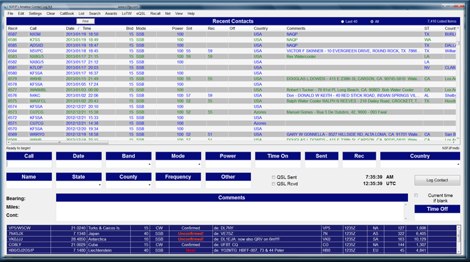 Amateur Contact Log (AC Log) by N3FJP is a commercial Windows-based general logging program designed for amateur radio operators, supporting Windows 7 through 11. It provides comprehensive tracking for various operating awards, including Worked All States (WAS), Worked All Counties, Worked All Countries (WAC), DXCC, VUCC, Grids, Zones, IOTAs, and Lighthouses. The software features a customizable user interface, allowing operators to display specific data fields and adjust font sizes. It includes built-in databases for counties and countries, facilitates queries by band, mode, or power level, and offers a bearing and distance calculator for DX contacts. AC Log also provides DX spotting via Telnet or packet TNC, supports keyboard CW, and can play wave files. The program offers full support for ADIF import and export, enabling seamless integration with external services like eQSL, QRZ, Club Log, and the ARRL's Logbook of the World (LoTW) for QSO uploads and confirmation downloads. It interfaces with popular transceivers from Elecraft, Icom, Kenwood, Ten Tec, and Yaesu, and connects with digital mode software such as WSJT-X, Fldigi, and JTAlert via API. AC Log includes a Net Manager form for group logging, prints basic QSL label strips, and integrates with QRZ and Ham Call lookup services. The software is fully networkable for multi-PC operation, supports Parks on the Air (POTA) logging, and displays worked entities and DX spots on a real-time world map. Full featured Trial version available for 45 days
 -

-
 CHIRP is a free, open-source, cross-platform radio programming tool that supports a large number of transceivers from manufacturers such as Icom, Kenwood, Yaesu, Alinco, Wouxun, Puxing, and Baofeng. Chirp radio software run on Windows, Linux, and macOS, enabling users to exchange data between different radio models and interface with multiple data sources and formats. The program streamlines the configuration of memory channels, frequencies, and various settings for amateur radio handhelds. Specific models supported include the _Icom IC-7300_, _Kenwood TH-D74_, and _Yaesu FT-818_, among many others. CHIRP provides compatibility with various file formats, including Generic CSV, RT Systems CSV, ARRL Travel Plus (.tpe), and manufacturer-specific formats like Kenwood KPG-44D (.dat) and Icom Data Files (.icf). Additionally, it integrates with the DMR-MARC Database for enhanced programming capabilities. Users can download CHIRP for their platform and access extensive documentation, including a FAQ and a mailing list for support. The project encourages users to consult existing documentation and open/closed tickets before submitting new bug reports or feature requests.
 -
 For amateur radio operators utilizing _APRS_ or requiring an external antenna for their GPS receiver, this resource details the construction of a compact, circularly polarized mobile antenna. The design is based on a classic turnstile configuration, employing two dipoles rotated 90° from each other and spaced a quarter-wavelength above a ground plane. A parallel-plate transmission line, fabricated from printed circuit board material, serves as both the connection method and mounting post for the dipoles, simplifying the feed network for circular polarization at 1.57542 GHz. The article outlines the fabrication process, starting with a 4-inch diameter hobby tin or brass base plate and #14 solid copper wire elements. It specifies using _RG-58/U_ or similar 50-ohm coax, with an 8-foot maximum length to minimize loss at the GPS frequency. The parallel-plate transmission line is constructed from two 2-inch lengths of single-sided _FR-4_ or G10 PCB material, 0.062-inch thick, with a specific 45° microwave turn cut on the active side. Final assembly involves an 8-ounce cream cheese container as a radome, and the article discusses the self-phased quadrature feed method to achieve circular polarization without a coaxial phasing line, resulting in an omnidirectional pattern suitable for GPS satellite reception.
 -
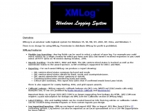 Version 7.22 of XMLog provides a fix for an issue where the ARRL LoTW application TQSL produced error messages concerning invalid "MY-COUNTRY" values, ensuring smoother integration for award submissions. The software supports flexible log searching, allowing users to select log subsets based on any field, such as RTTY QSOs on 40 meters during a specific month, or entries for a single country with sent but unreceived QSLs. XMLog tracks DXCC, WAZ, WAS, county hunting, IOTA, and grid square awards, managing QSL sent/received status and submission status to award sponsors, with LoTW crediting for DXCC and WAS. It generates detailed reports summarizing QSL status by band and mode, identifying needed countries/states/zones, and listing critical QSOs that could boost award totals. The system also integrates with callbook services like QRZ.com (subscription required) and WM7D.net for lookups, and facilitates QSL and mailing label printing using standard or custom layouts. Further capabilities include ADIF, Excel, and CSV log import/export, a Packet Window for Internet PacketCluster nodes or TNCs with history and scripting, and vocal/CW alerts for needed QSOs based on PacketCluster spots. Rig control is supported for a wide array of Alinco, Elecraft, Flex, Heath, Icom, JRC, Kenwood, TenTec, and Yaesu transceivers, enabling frequency/mode synchronization and control. CW support is provided via a serial port interface compatible with N1MM or K1EL WinKeyer, allowing CW sending from a keyboard or pre-programmed messages.
 -
 What is a dipole antenna and why are they so popular ? Arrl PDF file
 -
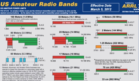 Download this color US ham radio band-plan in PDF format edited by ARRL
 -
 The article details the construction of a "bug-catcher" style HF mobile antenna, emphasizing its low cost and ease of tuning. It outlines the use of readily available materials such as PVC pipe, #14 house wire for loading and matching coils, and a _RadioShack_ replacement whip antenna. The design allows for operation across 20 through 6 meters, achieving an SWR of **1.5:1** or less on each band segment. The resource provides a comprehensive materials list, step-by-step assembly instructions, and photographs illustrating key construction phases. It explains how to create the coil forms, wind the coils, and secure them with epoxy putty. Crucially, the guide includes a table of suggested coil-tap positions and whip extensions for specific bands, such as 6 turns on the matching coil and 8 turns on the loading coil for 20 meters, facilitating initial tuning. Furthermore, the document discusses installation considerations, including grounding, and offers practical advice for tuning the antenna using an SWR meter. It highlights the antenna's broadband characteristics and its ability to collapse the whip for garage storage, making it a practical solution for mobile HF operation. The author, KM4IE, shares personal experiences with worldwide CW and phone contacts using this antenna.
 -

-
 About grid locators and grid squares, includes links to locator and grid square calculators
 -
-
 Arrl document about invisible antennas and indoor systems. It is important to consider that few compromise antennas are capable of delivering the performance one can expect from the full-size variety. But the patient and skillful operator can often do as well as some fellows who are equipped with high power and full-size antennas. The "cliff-dweller" may not be able to "bore a hole" in the band as often, and as easily, but DX can be worked successfully when band conditions are suitable.
 -
 WB2VUO presents a practical examination of effective HF mobile antennas, focusing on the inherent efficiency challenges encountered on the lower bands, specifically 160, 80, and 40 Meters. The resource delves into the necessity of loading coils for mobile operation below 21 MHz, where full-sized antennas are impractical. It contrasts base-loaded and center-loaded designs, noting that base-loaded antennas are simpler for the average ham to construct but offer lower efficiency compared to center-loaded configurations. The author provides specific data for an 8-foot whip, detailing its electrical length and _radiation resistance_ across various HF bands, from **0.08 ohms** on 160 Meters to **16.1 ohms** on 12 Meters. This data highlights the extremely low radiation resistance on lower frequencies, which significantly impacts feedpoint impedance due to ground and feedline losses. The discussion includes practical considerations for feedpoint impedance, noting that a typical 8-foot whip on 10 Meters might present 30-45 ohms, allowing for acceptable SWR without an ATU. Construction sketches illustrate both base-loaded and center-loaded mobile antennas, with advice on material selection like galvanized steel for rugged bottom sections. The article also includes coil value charts from the _ARRL Mobile Manual_ for both base and center loading, emphasizing the importance of using large diameter wire to minimize losses and suggesting capacity hats to reduce coil inductance and improve performance on 160-40 Meters.
 -
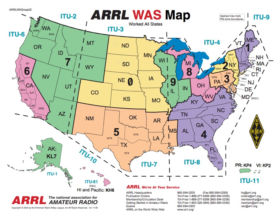 ARRL WAS Map, Map of USA call districts by ARRL and edited by AA70A
 -
 A modern version of the classic regenrative receiver designed and built by Charles Kitchin ARRL Article
 -
 Table of allocation of international Call Sign series
 -
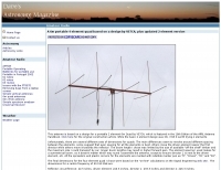 This antenna is based on a design for a portable 2 element 6m Quad by VE7CA, which is featured in the 19th Edition of the ARRL Antenna Handbook
 -
 A 10-meter J-Pole antenna, detailed in QST February 1950, offers a straightforward solution for hams operating with restricted space. This design, originally presented by W1BLR, is a **half-wave radiator** fed by a quarter-wave matching stub, providing a low-angle radiation pattern beneficial for DX. The article describes building the antenna from readily available materials like copper pipe, emphasizing its simplicity and effectiveness for **single-band operation**. The J-Pole's inherent design provides a good impedance match to 50-ohm coaxial cable without the need for an external tuner, a significant advantage for portable or minimalist stations. Its nondirectional pattern ensures coverage in all directions, making it a versatile choice for general operating on the 28 MHz band. The construction plans are clear, allowing even those with basic workshop skills to assemble a functional antenna.
 -
 The document is a PDF detailing the construction of the DBJ-1 VHF-UHF Dual Band J-Pole antenna for amateur radio use. It provides instructions on how to build a high-performance dual band base antenna for VHF and UHF bands using a single feed line for less than $10.
 -
 Presents the design and construction details for a VHF bicycle-mobile antenna, originally published in QST. The antenna utilizes a modified _Arrow J-Pole_ design, adapted for portable operation on a bicycle frame. Performance characteristics include a reported **1.5:1 SWR** across the 2-meter band, demonstrating effective impedance matching for typical handheld transceivers. Construction involves readily available materials, emphasizing lightweight components suitable for mobile deployment. The document provides a parts list and step-by-step assembly instructions, detailing the radiator and ground plane element lengths for optimal resonance at 146 MHz. Mechanical considerations for mounting on a bicycle are also addressed. The resource covers practical aspects of integrating the antenna with a bicycle, including cable routing and securing methods. It offers insights into achieving reliable VHF communications while operating in a mobile, low-power environment, making it relevant for field day activities or casual portable operation.
 -
 A 20 meter quarter wave vertical antenna by jerry sevick W2FMI QST Article
 -
 "ARES trains and organizes Hams to provide emergency communications to ""Served Agencies"" such as FEMA, National Weather Service, Red Cross, Salvation Army, Hospitals, and others. This site describes ARES goals and methods and structure."
 -
 Building guide for a two element quad antenna planned for 28 and 21 Megahertz
 -
 The ARRL ANTENNA Vol 5 COMPENDIUM features an article detailing two portable 6-meter antennas: a 2-element quad and a 3-element Yagi with telescoping elements. The 2-element quad exhibits a measured gain of **4.2 dB** over a dipole, while the 3-element Yagi achieves **5.8 dB** over a dipole. Both designs prioritize ease of construction and rapid assembly/disassembly for portable operations. Specific dimensions are provided for a 3-element 6-meter quad using #14 bare copper wire. The reflector element diameter is 6.2958 meters, the driven element 6.125 meters, and the director 5.8547 meters. Element spacing is 0.9398 meters between reflector and driven, and 1.1684 meters between driven and director. The SWR is under _1.26:1_ from 50 to 50.4 MHz, with a feed point impedance of 48.75 -j0.13 Ohms at 50.2 MHz, suitable for direct 50 Ohm coax feeding with a current _balun_.
 -
 All ARRL contests for current year are listed along to generic ARRL contest calendar is also provided that gives the weekends for all ARRL events. The Contest Corral files include non-ARRL events.
 -

-
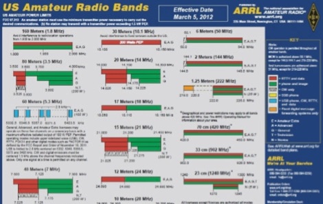 Transmitter power limits and frequencies allocation by band
 -
 Simple gain antennas for the beginner, a 2 element HF yagi antenna
 -
 VE7CA reprint an interesting article taken from arrl antenna compendium. Two elegant practical and portable 6-meter gain antennas, a two-element quad and a tree-element Yagi antenna for 50 Mhz-6 meter band
 -
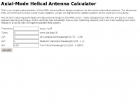 This is my simple implementation of the ARRL Antenna Book design equations for the axial-mode helical antenna.
 -

-

-
 Do your multiple-transmitter field day or contest efforts suffer from intrastation interference ?
 -
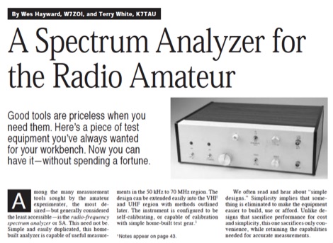 Demonstrates the construction of a **homebrew spectrum analyzer** designed by Wes Hayward, W7ZOI, and Terry White, K7TAU, enabling radio amateurs to build a capable test instrument without significant expense. The resource details a _double-conversion superheterodyne_ circuit, employing intermediate frequencies of 110 MHz and 10 MHz, and covers essential blocks such as the time base, logarithmic amplifier, resolution filters, and local oscillators. It highlights the use of hybrid and monolithic ICs, including mixers, amplifiers, and VCOs, to simplify construction while maintaining performance. The design supports useful measurements in the 50 kHz to 70 MHz range, with methods outlined for extending capabilities into VHF and UHF. The authors emphasize that this analyzer, while simple to build, is intended for serious measurements, requiring careful control of signal levels to avoid spurious responses. It uses an oscilloscope for display, with specific instructions for calibration and adjustment of various stages, including the log amplifier and IF gain. The guide provides detailed schematics and component lists for each section, such as the 110 MHz triple-tuned band-pass filter, which achieved **90 dB** image rejection, a significant improvement over double-tuned circuits. Practical advice on alignment and troubleshooting is included, drawing on the authors' extensive experience in RF circuit design.
 -
 RFI/EMI RadioFrequency interference/electromagnetic interference by ARRL Technical Information Service page
 -
-
 Operating within the amateur radio HF spectrum requires adherence to established band plans and considerate practices. This guide from the ARRL outlines commonly accepted frequency ranges for specific modes and activities, spanning from 1.800 MHz to 29.680 MHz. It delineates segments for **CW**, **SSB**, RTTY/Data, SSTV, Digital Voice, and AM operations, including dedicated QRP calling frequencies and DX windows. The document emphasizes that these are not regulatory mandates but rather widely recognized conventions, acknowledging that high-activity periods like DXpeditions or contests may lead to temporary deviations. It explicitly references Section 97.101(b) of the FCC Rules, asserting that no station holds exclusive rights to any frequency. The guide also lists frequencies for IBP/NCDXF beacons and automatically controlled data stations. Practical advice is provided regarding frequency selection, stressing the importance of checking for existing use before transmitting. It also mentions ARRL band plans for frequencies above 28.300 MHz, directing operators to additional resources.