Search results
Query: lower bands
Links: 46 | Categories: 1
-
 Demonstrates the construction of **magnetic loop antennas**, detailing both multi-turn and single-turn designs. It covers a 30-inch diameter multi-turn loop for 80 meters, based on a February 1996 QST article, and an octagon single-turn loop made from 15mm copper tube with a 4.8-meter circumference, operating from 7 MHz to 14 MHz. The document also presents a smaller 800mm diameter loop for 14 MHz to 28 MHz, emphasizing the importance of high-voltage tuning capacitors. Covers the design and construction of custom **butterfly capacitors** and piston capacitors, including a split stator capacitor with 140 pF capacitance and a 6000 Volt rating, and a butterfly capacitor with 5-65 pF and 7200 Volt rating. It explains why butterfly capacitors are preferred over split stator types for high power applications due to lower losses and direct series connection of rotors, reducing resistive losses from wiper contacts. Material recommendations include clear PVC for plates and brass or stainless steel for non-magnetic hardware. Addresses practical considerations such as feeding the loop with a shielded 1/5 Faraday loop made from RG213 or RG8 coax, achieving VSWR 1.1 across bands, and optimizing its placement 180° from the capacitor. It also discusses mechanical joint resistance, dissimilar metal oxidation prevention using Vaseline, and a simple method for determining radiation angle with a TL-light tube. The guide includes diagrams for rotor, stator, and end plate construction.
 -
 This Vertical antenna design by David Reid for lower bands focuses on achieving effective DX communication by optimizing the antenna low-angle radiation for long-distance contacts. The design incorporates techniques like linear loading and capacity hats to reduce the antenna's height while maintaining performance, especially on 40m and 80m bands. Building a solid ground plane and using quality materials ensure efficiency and durability. Although vertical antennas can be complex to build, this project simplifies the process, making it accessible for ham operators seeking strong, reliable signals.
 -
 Examines the operational differences between **quad** and **Yagi** antenna designs, focusing on their respective performance characteristics for amateur radio applications. The document highlights key metrics such as forward gain, front-to-back ratio, and bandwidth, which are crucial for effective DXing and contesting. It discusses how element configuration, boom length, and material choices impact the efficiency and radiation patterns of each antenna type across various HF bands. Practical considerations for antenna builders are addressed, including structural integrity, wind loading, and overall weight, particularly when using fiberglass spreaders for quads. The resource also covers precipitation static reduction in quads due to their closed-loop design and their ability to operate efficiently at lower elevations compared to Yagis. It provides insights into dual-polarization feed systems for quads, offering independent vertical and horizontal feed points for enhanced operational flexibility.
 -
 A self-supporting vertical antenna design for stationary-mobile HF-VHF operation is presented, emphasizing ease of construction with common materials like a fiberglass fishing rod and PVC pipe. The design focuses on creating a set of no-tuner monoband radiators for bands such as **2m**, **6m**, 10m, and 12m, with an overall radiator support length of 3.3m. The construction process details the assembly of the antenna base using a magnetic mount, PL-259 connector, and PVC pipe sections, which then supports the telescopic fishing rod. Radiator extensions are cut to achieve quarter-wave resonance on specific bands, with detailed instructions for 6m (50-51 MHz), 10m (28.5 MHz), and 12m (24.9 MHz). For lower HF bands like 15m, 17m, and 20m, the design incorporates base-loading coils, with specific turn counts provided (e.g., 21 turns for 20m). The project also suggests using an _antenna analyzer_ for precise tuning of extensions and coils, moving beyond theoretical values to achieve optimal performance. The author, _IK1ZYW_, notes that for 80m and 160m, the antenna becomes less efficient as a vertical, suggesting alternative configurations like an inverted-V dipole or asymmetrical inverted-L.
 -
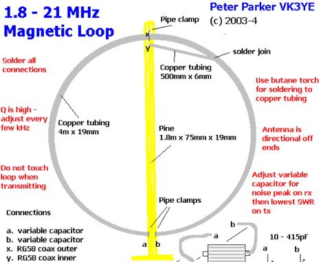 Magnetic loops are a compromise antenna and performance will be down on a full size-wire antenna particurlarly on lower HF Bands. This article compare this magnetic loop with a full-sized wire antenna on 80 meters by VK3YE
 -
 The 80-meter loop antenna, measuring 86 meters (282 feet) of wire, effectively operates across 8 HF bands from 80 through 10 meters, despite its length being a compromise for specific bands. This design prioritizes a "low enough" SWR across multiple bands, aiming for lower SWR values on higher frequencies due to increased feedline losses. A 200-ohm feedpoint impedance provides a workable SWR on every band, with feedpoint impedances ranging from 100 ohms for lower bands to 300 ohms for higher bands. Radiation patterns for the 80-meter loop, mounted at 15 meters high, show a maximum gain of 7.6 dBi at a 90-degree takeoff angle on 80 meters, and up to 12.9 dBi at a 10-degree takeoff angle on 12 meters. This configuration supports regional contacts on 80 meters and provides good DX performance on higher bands. Practical construction notes emphasize using robust supports like trees, ensuring wire slack with _egg insulators_ for wind resilience, and employing an oversized 2 kW 4:1 _balun_ to safely handle higher SWR conditions, even with 100W transceivers. Feedline losses are minimized using _LMR-400_ coax or ladder line, with power transfer efficiency between 80% and 95%. Antenna simulations were performed using _xnec2c_, and the provided NEC file is compatible with other NEC2 derivatives. The antenna is tunable on 6 of 8 bands with an internal ATU and all 8 bands with an external autotuner like the LDG AT-200 Pro.
 -
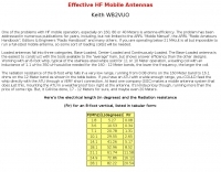 Effective HF Mobile Antennas Keith WB2VUO, explains difficulties on gaining antennas efficiency on lower bands with mobile antennas.
 -
 F6EZX presents a detailed account of constructing a compact, multi-band _Levy antenna_ for portable holiday operations, specifically addressing issues with local QRM from a previous _Deltaloop_ setup. The article outlines the design criteria, including multi-band operation on 40m, 30m, 17m, 15m, 12m, and 10m, a symmetrical configuration to reduce interference, and a low take-off angle for DX. Construction involves 2x 10.3m radiating elements and a 15.3m open-wire feeder (ladder line) with 7cm spacing, made from 1.5mm2 copper wire and foam pipe insulation spacers. Theoretical calculations, referencing F9HJ's "_Les antennes Levy_" book, guide the determination of element lengths and feeder impedance characteristics, aiming for a good match across bands with a commercial antenna tuner. Initial field tests with the _VCI Vectronics VC300DLP_ tuner showed a 1:1 SWR from 80m to 10m, with some difficulty on 17m. The antenna, mounted as a 45-degree slopper with the high point at 12m, successfully facilitated DX contacts to South America, particularly Chile and Argentina, suggesting a lower take-off angle compared to the previous Deltaloop which favored Brazil. The Levy antenna significantly reduced TVI/RFI, attributed to its improved symmetry and greater distance from the QRA. While signal reports on 15m and 20m were 1-2 S-points lower than the Deltaloop, its performance on 40m and 30m was comparable, fulfilling the design goals for a portable, low-cost, multi-band solution.
 -
 Presents G0GSF Brian's ZS6BKW antenna, a refined iteration of the classic G5RV, offering improved performance across multiple HF bands. The design emphasizes specific radiator and ladder line lengths to achieve lower SWR on 40m, 20m, 17m, 12m, and 10m, making it a practical choice for operators seeking a single wire antenna solution. The document includes critical dimensions for the flat-top and the 450-ohm ladder line section, which are key to its multiband resonance characteristics. Unlike the original G5RV, the ZS6BKW aims for direct 50-ohm feedpoint impedance on several bands, reducing the need for an external antenna tuner. My field experience with similar optimized dipoles confirms that precise construction, particularly the ladder line length, is paramount for realizing the intended SWR benefits. This design offers a compelling alternative for hams with limited space or those preferring a less complex antenna system.
 -
 The 6 Band Inverted L Antenna MK3 is a versatile multiband antenna designed for amateur radio operators. This antenna covers 160m, 80m, 40m, 20m, 15m, and 10m bands, making it suitable for a wide range of HF communications. The design is based on a W3DZZ configuration, incorporating traps for optimal performance. The MK3 version features a sturdy 5/8th CB mast, replacing the original timber mast, which enhances durability against harsh weather conditions. The antenna's construction allows for effective operation, particularly on the 40m band, where it has been successfully used to contact distant locations including ZL, VK, and Antarctica. Constructing this antenna requires careful attention to detail, especially regarding the radials and grounding. The traps resonate at specific frequencies, and additional resources are available for building coaxial traps. The antenna is designed to work efficiently without an ATU on the lower bands, while higher bands may require tuning. This project is ideal for both beginner and intermediate operators looking to enhance their station with a reliable multiband antenna.
 -
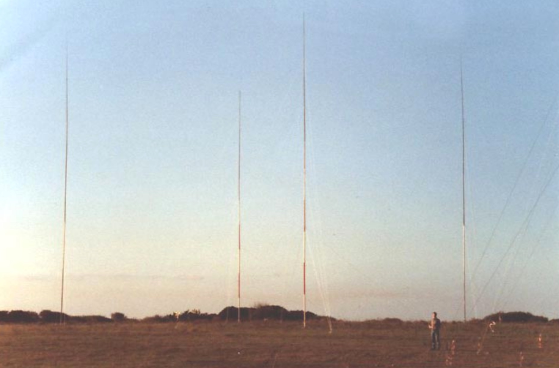 This page is a short description of the four phased verticals system i've build and used. It is primarily intendend to be used on the lower bands 160m, 80m, 40m.
 -
 A quarter-wave vertical antenna design for HF operation offers a practical solution for radio amateurs seeking a compact and efficient multi-band radiator. This project details the construction of a 5-band HF vertical, drawing inspiration from established commercial products such as the _DX COMMANDER_ and the MV6. The design emphasizes ease of assembly and disassembly, making it suitable for portable operations or installations with limited space. The article provides insights into various construction methods and offers practical tips for building a robust yet lightweight antenna. It highlights the benefits of a vertical configuration for DX contacts, particularly on the lower HF bands, and discusses real-world performance observations. The antenna is designed to cover multiple HF bands, providing versatility for various operating scenarios. Operators can achieve significant DX results with this type of antenna, often comparable to more complex arrays, especially when deployed with an effective ground system. The project aims to empower hams to build a capable antenna without significant financial outlay.
 -
 JJ0DRC's HF multi-band delta loop antenna project, initially conceived during the waning peak of Cycle 23, addresses the common challenge of achieving effective DX operation from a small residential lot in Japan. Dissatisfied with a ground plane antenna's performance in SSB pile-ups, the author sought a beam-like solution without a tower, drawing inspiration from a JJ1VKL article in CQ Ham Radio Sep. 2000. The antenna, constructed in October 2000, employs two 7.2-meter fishing rods (37% carbon fiber, reinforced with cyano-acrylate glue and aluminum tape) and 1mm enameled wire, fed by an Icom AH-4 external antenna tuner. While the exact beam pattern remains unmeasured, JJ0DRC observed a significantly higher callback rate compared to dipole antennas, particularly on higher bands. The system's circumference length of 15-20m is crucial for maintaining a good beam pattern across HF bands, though performance on lower bands like 80m, 40m, and 30m becomes less directional as the length deviates from a full wavelength. Ongoing maintenance addressed degradation issues, including aluminum tape cracking and wire breakage at connection points due to strong winds (often exceeding 10-15m/s in winter). The author reinforced rod connections with IRECTOR PIPE SYSTEM components and INSU-ROCK ties, and improved wire attachment methods using Cremona rope and epoxy bond to enhance durability.
 -
 The ZS6BKW wire antenna, a variant of the G5RV, utilizes a specific 13m (42.6 ft) length of 450-ohm window line as its matching section, feeding a 28.5m (93.5 ft) flat-top element. This design aims for lower SWR on 40m, 20m, 17m, 12m, and 10m compared to a standard G5RV, often achieving SWR values below 1.5:1 on these bands without an antenna tuner. The feedpoint impedance transformation provided by the window line allows for direct connection to 50-ohm coax on multiple bands. F4FHH's experience involved constructing the ZS6BKW and evaluating its performance against an _OCF dipole_ (Off-Center Fed) on various HF frequencies. The article includes observations on SWR readings and operational effectiveness, highlighting the ZS6BKW's suitability for multi-band operation. The antenna's overall length, including the flat-top and window line, is approximately **41.5 meters** (136 feet), making it a significant wire antenna for fixed station use. Comparative analysis with the OCF dipole provided practical insights into the ZS6BKW's advantages and limitations, particularly concerning bandwidth and tuner requirements.
 -
 Demonstrates the design principles and performance characteristics of **corner reflector antennas**, emphasizing their high gain and directional properties. It covers critical design factors such as the corner angle and the spacing between the radiating dipole and the reflector vertex. The resource explains how reducing the corner angle increases gain but lowers feed impedance, making matching more challenging. Practical angles of 90 degrees or 60 degrees are discussed, with 90 degrees offering easier impedance matching despite slightly lower gain. Details key design considerations, including reflector side length exceeding two wavelengths and reflector width greater than one wavelength for a half-wave radiator. It specifies reflector construction using wire netting, sheet metal, or parallel metal spines spaced less than 0.1 wavelength. The article provides a table with general dimensions for UHF and VHF bands, noting typical impedance values of 50 to 75 ohms and expected SWR of 1.7:1 on the lower band edge. Adjustable radiator-to-vertex spacing is highlighted as crucial for final tuning.
 -
 A lower power desktop linear with integrated 120vac power supply. This, very compact, dual 811 version will deliver about 300 watts output. Covers all bands including WARC bands.
 -
 A 50-ohm 10W resistor forms the core of this portable QRP antenna, designed by _K0EMT_ for convenient operation on 160m and 80m. The construction involves soldering the resistor to a BNC connector, with one lead to ground and the other to the center conductor, then insulating the assembly. This minimalist design aims to provide a highly portable solution for low-band QRP operations, acknowledging the inherent trade-offs between antenna size and efficiency. Testing with an antenna analyzer revealed low SWR on both 160m and 80m, with a Yaesu FT-817 confirming good matching. While 40m and 30m showed higher SWR, the primary focus remains on the lower bands. The author successfully tested the antenna with **2.5W CW** output, demonstrating its practical application for QRP field operations where ease of deployment is paramount, even if it means sacrificing some **gain** compared to full-sized antennas.
 -
 A 21 MHz Four Square Beam Antenna This popular antenna for the lower bands, can also work well on 15 meters, QST Article
 -
 The X80 multi-band HF vertical antenna, a commercial iteration of the Rybakov design, exhibits a physical length of 5.5 meters, or approximately 18 feet, and is constructed from aluminum tubing. It operates as a non-resonant vertical, requiring an external antenna tuner for impedance matching across its intended operating frequencies. The antenna's design incorporates a 1:4 UNUN at its base, facilitating a nominal 50-ohm feed point impedance for the coaxial cable. Performance observations indicate effective operation on 40 meters, 20 meters, 15 meters, and 10 meters, with reduced efficiency on 80 meters and 160 meters due to its relatively short electrical length for these lower bands. Comparative analysis with a G5RV dipole and a half-wave end-fed antenna reveals the X80 offers a lower take-off angle, beneficial for DX contacts, particularly on the higher HF bands. Field tests conducted with an Icom IC-706MKIIG transceiver and an LDG AT-100ProII autotuner demonstrate the X80's ability to achieve acceptable SWR across 80m through 10m. The antenna's compact footprint and ease of deployment make it suitable for restricted spaces or portable operations, though its performance on 80 meters is noted as a compromise compared to full-size resonant antennas.
 -
 The resource details the construction of a homebrew 50-watt FET amplifier, based on Don W6JL's _QST Homebrew contest_-winning design from 2009. It functions as an afterburner for QRP transceivers, providing a **12dB** power lift. The amplifier utilizes IRFZ24N FETs and covers the 80, 40, 30, and 20-meter bands, with the 20m LPF extending to 17m. Key technical aspects include an FT37-43 transformer for the input network, a relay-switched 3dB pad for lower bands controlled by an _Arduino Nano_, and an RF-actuated T/R switch. The LPF board integrates four relay-switched filters rated for 50 watts, using capacitors with a minimum 250VDC rating. Performance measurements indicate a power gain ranging from **4.4dB** on 20m to 8.1dB on 80m, with a required drive power of approximately 5 watts. The article also discusses thermal management, current limiting considerations, and component sourcing.
 -
 Over 130 years after its inception, Morse Code remains a fundamental skill for many amateur radio operators, enabling efficient QRP operations, DXing, and contesting. This resource provides an in-depth look at the **Koch Method** of Morse training, a widely adopted technique that emphasizes high-speed character recognition from the outset. It details how this method can significantly accelerate proficiency, moving beyond traditional, slower learning approaches. The site also delves into the rich history of amateur radio, presenting articles such as "Radio on the Rio," which chronicles local ham activity in Socorro, New Mexico. Another piece, "The Russian Woodpecker," recounts the Cold War-era efforts of hams to counter Soviet over-the-horizon radar interference on the HF bands. Furthermore, the resource explores the fascinating intersection of ham radio and radio astronomy, highlighting the direct lineage between amateur experimentation and the development of modern radio telescopes like the **Very Large Array (VLA)**. It also includes an introduction to the 6-meter band, often called "The Magic Band," detailing its unique propagation characteristics and suitability for no-code licensees seeking long-distance contacts.
 -
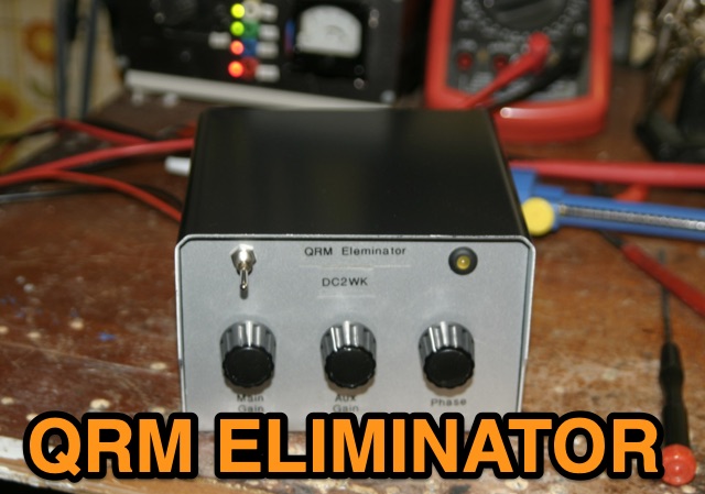 A home made project to reduce noises from lower bands, an X-Phase QRM Eliminator project that can help you a lot
 -
 Message list about 903 Mhz. and above bands. Use various VHF reflectors for the 432 and lower bands. Most traffic will be about 2304 and above.
 -
 The Buddipole Deluxe, a portable HF/VHF antenna system, receives a practical assessment from IW5EDI after a month of field use. The author, constrained by antenna restrictions, highlights the system's crucial role in enabling portable operations, even managing sporadic digital activity from a balcony. Direct comparisons to a fixed 3-band dipole reveal surprisingly comparable signal reports on 15, 17, and 20 meters, underscoring the Buddipole's effectiveness in real-world scenarios. Tuning the Buddipole proves straightforward on bands down to 20 meters, though the review notes significant challenges with SWR on lower bands like 40 meters, where achieving better than 3:1 SWR was problematic. Observations also include SWR variations with dipole rotation and mast height, suggesting environmental factors play a role. The overall manufacturing quality of the antenna and its accessories, including the tripod and carry bag, is deemed good, despite a minor issue with a pole connector. Looking ahead, the author plans to construct a homemade Buddipole version, possibly optimized for the 30-meter band, specifically for PSK31 operations from an apartment. This personal project reflects a common amateur radio practice of adapting commercial designs for specific needs, further extending the utility of portable antenna concepts.
 -
 Understanding the operational impact of Broadband over Power Line (BPL) on amateur radio communications is crucial for any radio amateur, especially given the potential for significant radio frequency interference (RFI). This ARRL tutorial delves into the technical aspects of BPL, explaining how the technology operates by transmitting data over existing electrical power lines, which can inadvertently radiate broadband noise across various amateur bands. My own field experience, particularly on the lower HF bands, has often involved tracking down noise sources that exhibit characteristics consistent with BPL emissions, making this a pertinent topic for maintaining clear receive conditions. The resource further details the specific FCC rules and regulations implemented to restrict BPL deployment. These regulations aim to protect licensed radio services, including amateur radio, from harmful interference. It outlines the technical standards and operational limitations imposed on BPL systems to minimize their impact on the electromagnetic spectrum, a critical aspect for contesters and DXers alike. For those engaged in RFI mitigation, the tutorial provides a foundational understanding of the regulatory framework that can be leveraged when addressing BPL-related interference issues. It serves as a valuable reference for hams seeking to comprehend the technical challenges and regulatory solutions surrounding this pervasive noise source.
 -
 The article, "Using 75 Ohm CATV Coaxial Cable," details methods for employing readily available 75-ohm CATV hardline in standard 50-ohm amateur radio setups. It addresses the inherent impedance mismatch and practical considerations, such as connector compatibility, for hams seeking cost-effective, low-loss feedline solutions. The resource specifically contrasts common 50-ohm cables like RG-8, RG213, and _LMR-400_ with 75-ohm hardline, highlighting the latter's lower loss characteristics, particularly at VHF and UHF frequencies. It explores two primary approaches to manage the impedance difference: direct connection with an acceptable SWR compromise and precise impedance transformation. The direct connection method acknowledges that a perfect 1:1 SWR is not always critical, especially when using low-loss coax. For impedance transformation, the article explains the use of half-wavelength sections of coax to reflect the antenna's 50-ohm impedance back to the transmitter, noting its single-frequency effectiveness. It also briefly mentions transformer designs using toroid cores and a technique involving two 1/12 wavelength sections of feedline for broader bandwidth. The content further clarifies the concept of _velocity factor_ for calculating electrical versus physical cable lengths, providing a generic formula for precise length determination. It notes that while half-wave matching is practical for 10 meters and above, it can result in excessively long runs for lower bands like 160 meters, potentially adding **250 feet** of cable. The article also mentions achieving a usable bandwidth of 28.000 MHz up to at least **28.8 MHz** on 10 meters with specific transformation techniques.
 -
 Full article on how to build a home-made wire dipole antenna for 40 and 80 meters band. Article is fully in italian, as it was published on ARI RadioRivista, but is plenty of self explaining pictures that will guide you on homebrewing this trapped dipole antenna for the lower amateur radio bands.
 -
 Constructing a multi-band fan dipole for HF operation presents unique challenges, as VE2XIP demonstrates through his 2012 project to replace an existing commercial antenna. He details the process of calculating wire lengths using the 468/frequency formula, emphasizing the critical importance of equal leg lengths for each dipole element. The author shares practical insights gained from building at ground level, noting how elevation impacts resonant frequency and SWR, particularly for lower and higher bands. VE2XIP's experience highlights the iterative nature of antenna tuning, starting with the lowest frequency band (80m) and working upwards. He provides a specific example of trimming calculations and offers a clever tip for accurate wire removal. The article also touches on the mechanical aspects, such as dowel spacing for wire support and the benefits of a pulley system for repeated raising and lowering during the tuning process. Field results showed significant performance gains over the previous Alpha-Delta DX LB Plus, with **20 dB over 9** signal reports on 80m compared to 57. The project cost around **$100** for hardware, proving a cost-effective alternative. The author also discovered a bonus 6m capability and achieved an inverted-V _obtuse angle_ of approximately 115 degrees, contributing to a surprisingly stealthy installation.
 -
 The Buddistick antenna, as demonstrated by KP4MD, effectively handles up to **250 watts** and provides coverage from 40 through 10 meters, with an optional coil extending operation to 80 and 60 meters. KP4MD's video presentation meticulously describes the antenna setup, emphasizing the critical role of the _shunting coil_ for achieving resonance on lower bands like 40 and 80 meters. This practical approach highlights how a compact antenna can deliver solid performance from a constrained location. SWR curve diagrams are included, clearly illustrating the impact of the shunting coil on the antenna's resonating frequency. These visual aids provide concrete evidence of the adjustments needed for optimal operation across different bands, particularly when space is at a premium. KP4MD's insights are particularly valuable for hams operating from apartments or other limited spaces, showcasing real-world results from a balcony installation.
 -
 The Tri-pole antenna, a clever modification of a standard dipole, allows for dual-band operation by integrating a third element. This design effectively shortens the overall dipole length by 10 to 20 percent, simplifying antenna rotation and offering a compact footprint. KK4OBI's article delves into the operational principles, using a 6 and 10-meter Tri-pole as a primary example, and provides comprehensive instructions for constructing any Tri-pole antenna within the 6 to 15-meter range. Key to the Tri-pole's performance is its off-center feed, necessitating a common mode choke at the feed point for optimal tuning and reduced noise. The author outlines a methodical approach to determining element dimensions, starting with a vertical element frequency calculated as 0.47 times the sum of the desired upper and lower band frequencies. This calculation, along with K-values derived from trend lines, guides the initial lengths for the horizontal arms, demonstrating how a 10m-6m Tri-pole can achieve a total horizontal length 78% shorter than a conventional 10-meter dipole. Tuning and balancing are critical, with the article detailing adjustments to arm lengths and the vertical element to achieve balanced SWR values, as validated through 4NEC2 simulations. Radiation patterns are analyzed at various elevations, showing gains around 5.7 dBi and favorable take-off angles for DX contacts. Construction details specify aluminum tubing dimensions, U-bolts, and an SO-239 connector, emphasizing the importance of a ferrite-based choke for wideband operation.
 -
 F5NPV introduces a variant of the W8JK antenna design, employing the MOXON principle. With extended monopoles, it outperforms the Open-Folded W8JK, yielding a 1dbd gain improvement, enhanced performance on 30m and 10m bands, bi-directionality, and lower side attenuation. The design's focus on higher radiation impedance results in increased antenna efficiency and reduced losses. Despite these improvements, the bill of materials remains unchanged.
 -
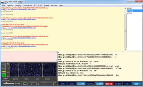 FSQ is a Fast Simple QSO mode designed specifically for HF. It works well under NVIS and sunrise/sunset conditions on the lower bands, and also works well for short skip and grey-line on higher bands and can be used also on VHF FM.
 -
 Choking balun for lower HF and MF bands. (1.8MHz - 10MHz). Requiring a choking balun to isolate the potential RF pick up on the coax cable as it runs past equipment such as computer within the radio room at lower HF and MF frequencies a simple method of winding RG58 coax onto a Powdered Iron Toroid Core was constructed.
 -
 Learn how to easily build a 10-meter vertical antenna, perfect for DX contacts on the amateur radio bands. This flowerpot or T2LT design is portable, efficient, and ideal for ham radio operators looking to improve their DX performance. With just a few basic tools and materials, you can construct this antenna for portable operations or as a home station setup. Discover how to set up the antenna, improve its performance by raising it higher, and start making contacts with stations around the world. Watch a step-by-step guide on YouTube for building and testing this DIY ham radio antenna.
 -
 This article introduces an Arduino-based QRP CW Transceiver designed for lower HF bands. The journey begins with the Wotduino, evolving from a keyer to a multi-mode beacon. The development includes a QRP transmitter and culminates in a receiver inspired by Roy Lewallen design. The transceiver, controlled through a control bus features a signal path, modulation, filtering, and adjustable frequency settings. Despite initial testing intentions, successful QSOs on 80 and 40 meters showcase its functional capabilities.
 -
 Operating an amateur radio station effectively requires reliable coaxial cable to minimize signal loss between the transceiver and antenna. SIVA Cavi, an Italian manufacturer, produces a range of coaxial cables, including specific 50 Ohm low-loss types suitable for amateur radio applications. Their product line features cables like **RG 58 SHF1**, **RG 213 SHF1**, and **RF 400 SHF1**, which are commonly deployed in HF and VHF/UHF setups. The company also offers specialized cables such as the **HF 214 UF Ultraflex**, a high-performance broadband low-loss 50 Ohm cable designed for flexibility and reduced attenuation across various amateur bands. These cables are engineered with solid or foam dielectric materials, impacting their electrical characteristics and suitability for different power levels and frequency ranges. For instance, foam dielectric cables often exhibit lower loss at higher frequencies, a critical factor for VHF/UHF operations. Beyond amateur radio, SIVA Cavi manufactures cables for digital video broadcast, offshore marine use, and fire detecting systems, demonstrating a broad engineering capability in coaxial cable technology.
 -
 A Trapped dipole inverted V antenna for lower HF Bands. Construction details are for temporary installation. Permanent installations will require additional ruggedising and waterproofing however the basic electronics concepts remain the same. This project includes SWR plots for the three bands and pictures details of the homemade traps.
 -
 This study details a reception comparison between vertical and horizontal active loop antennas, specifically two identical _Wellgood active loop antennas_, on various HF bands. The experiment, conducted in a densely populated QRM-prone area, monitored FT8 signals over a 24-hour period using two identical receivers. The methodology involved direct comparison of signal reception across the HF spectrum, aiming to identify performance differences based on antenna orientation. The results indicate that vertical loops demonstrated superior performance on higher bands (10m, 15m, 20m), while horizontal loops excelled on lower bands (30m, 40m, 160m), particularly for receiving long-distance (DX) signals. The horizontal loop's advantage on lower bands is attributed to potentially better low-angle performance and reduced sensitivity to man-made noise, yielding a **2-3 S-unit** improvement on 160m. The study provides practical insights for optimizing antenna placement in challenging urban environments, noting that the horizontal loop consistently showed a **10-15 dB** signal-to-noise ratio improvement on lower bands.
 -
 An cheap and efficient wire antenna for lower HF bands. This closed loop antenna, radiates perpendicular to its plane with a bi-directional radiation pattern. With a gain of 2 dB over a diplole it is a low noise sensible antenna. Requires a tuner if you want to use as a multiband antenna.
 -
 A vertical delta loop is a practical antenna for low bands, popular for its simple design requiring just one support. Its shape, an equilateral triangle in free space, yields optimal gain and radiation resistance. Deviating from this shape lowers performance. The delta loop can be polarized either horizontally or vertically based on the feed point location. In vertical polarization, it acts as two quarter-wave verticals with the baseline feeding one side. This design minimizes radiation from the baseline while maintaining effective operation.
 -
 The Butternut HF2V, originally a two-band vertical antenna for 80m and 40m, was enhanced by the user to include 30m and 20m bands for better digimode DX work during the solar minimum. The additions used components adapted from the HF6V and innovative methods for the 20m addition, either through a parallel vertical element or a lower-mounted independent element, minimizing band interaction. This modified four-band antenna now supports high power across popular HF bands using a single feedpoint.
 -
 Effective suppression of harmonics and parasitic radiation from HF transmitters is crucial, especially with the increasing sensitivity of VHF/UHF radio channels to interference. This project details a hybrid low-pass filter (LPF) designed to operate across the HF bands up to 51 MHz, making it suitable for 6-meter band operations while providing deep VHF/UHF suppression. The design addresses the challenge of modern interference landscapes, where even microvolt-level signals can disrupt wireless sensors and other simple VHF/UHF receivers. The filter utilizes a single elliptic link, combining high cutoff steepness with robust suppression in the hundreds of megahertz range. A key feature is the use of only two standard capacitor values, simplifying construction and component sourcing. The article provides a detailed schematic, performance characteristics, and _RFSim99_ model file, demonstrating a reflection coefficient S11 below 0.017 (VSWR < 1.03) across 1-51 MHz, ensuring minimal degradation to the antenna system. Construction notes include coil winding specifications and capacitor selection guidance, with recommendations for _FR-4_ assembly. Two capacitor sets are presented, with the first variant recommended for its lower RF current demands, keeping currents below 3 A at 1 kW passing power at 51 MHz. Fine-tuning involves adjusting frameless coils, with considerations for capacitor tolerance and high-frequency capacitance measurement accuracy.
 -
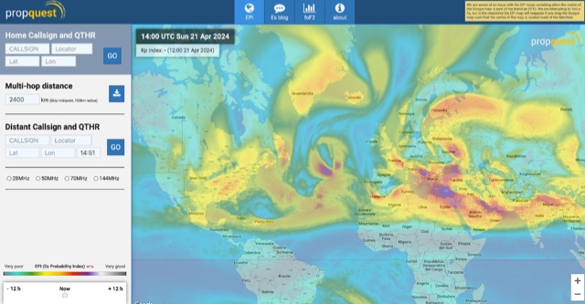 This website explains signal variations on a local radio net by tracking the foF2, a measure of ionosphere's ability to reflect radio waves. The website shows daily foF2 variations and how it affects Near Vertical Incidence Skywave (NVIS) propagation for local nets. It also considers D-layer absorption affecting lower bands and F2 MUF distance for long-distance communication. Additionally, the website tracks foEs for E-layer propagation and an EPI index for predicting Es chances.
 -
 Rob Conklin N4WGY delivered an informative presentation on Hexagonal Beam antennas (Hex Beams), detailing their construction, performance, and benefits over traditional multiband Yagi antennas. He highlighted their cost-effectiveness, lower wind loading, lightweight design, and multi-band capabilities without requiring traps. Conklin also discussed the improved G3TXQ design, which offers better SWR performance across ham bands. The presentation included practical construction tips, resource recommendations, and demonstrations of performance analysis tools, making it a valuable resource for both novice and experienced antenna builders.
 -
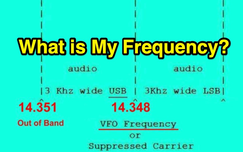 Single Sideband (SSB) operation requires careful attention to the relationship between a radio's displayed frequency (suppressed carrier) and the actual 3 kHz wide audio signal. This resource clarifies how Upper Sideband (USB) and Lower Sideband (LSB) signals occupy spectrum above or below the indicated frequency, respectively. It provides practical examples for General Class operators on the **20m** and **40m** bands, such as setting a VFO to 14.226 MHz for USB on 20m or 7.178 MHz for LSB on 40m, to maintain a safe margin from band edges. The resource emphasizes the critical importance of staying within allocated band limits to prevent out-of-band emissions, particularly when operating close to band edges. It includes relevant excerpts from **FCC Regulation Part 97**, specifically section 97.307, which details emission standards, necessary bandwidth, and spurious emission attenuation requirements. The text explains that unused sidebands are considered spurious emissions and notes that modern HF equipment typically exceeds the 43 dB spurious emission reduction standard, often achieving 60 dB or more.
 -
 This is a theoretical look at propagation on 630-Meters and 2200-Meters using ray tracing software. It expands on the brief discussion in the ARRL Handbooks. The Earth's magnetic field affects 630-Meter and 2200-Meter band propagation. Lower ionization reduces absorption, aiding low-frequency propagation. Differences exist between bands, limited daytime sky-wave propagation. Sunrise/sunset show promise, yet mechanisms are unclear. Ducting possible at night in specific conditions. Negative ions enhance propagation. Inefficient antennas and high man-made noise are anticipated. Groundwave propagation is significant on 2200-Meters.