Search results
Query: step up
Links: 104 | Categories: 0
-
 SysLabs RadioControl is a software platform for radio device control and application development. It operates on _Windows_ versions from Windows 95 and Windows NT 4.0 through _Windows 11_. The software is available in Lite, Standard, and Professional editions, each including Frontpanel for direct radio control, a Frequency Database for management, and a Memory File for channel operations. Features include frequency identification, memory scanning, and graphical spectrum views with bitmap export capability. The Professional Edition supports multi-device control and utilizes radio device-internal scanners, achieving scan rates of **40-60 steps per second** compared to the RadioControl-internal scanner's **10-20 steps per second**. Supported devices for internal scanning include AOR AR-5000, AR-8200, AR-8600, AR-ONE, R&S EB200, and various Icom receivers and transceivers. RadioControl supports older devices such as ICOM IC-R71, IC-R7000, IC-706, IC-735, YAESU FRG-8800, and FRG-9600, extending their control capabilities. The platform offers APIs for integration and supports import/export with formats from VisualRadio, SCANcontrol, shoc Radio Manager, WiNRADiO, AOR ACEPAC-3A, as well as generic Text, CSV, and HTML. DXZone Focus: Radio Control | Windows | Frequency Management | API
 -
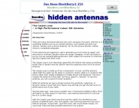 High performance indoor shortwave antenna, the Carpet Loop II is an ideal step upward for the listener who wants something better than a random wire but doesn't want the expensive dice roll of an active antenna.
 -
 Presents a practical design for a **crossed-dipole turnstile antenna** specifically engineered for 2-meter Amateur Radio Direction Finding (ARDF) events. The author, WB6RDV, details a robust, omnidirectional, horizontally-polarized antenna, addressing the international ARDF rules requiring such characteristics at a height of two to three meters above ground. This contrasts with the vertical polarization often used in Southern California, highlighting the design's adherence to specific event requirements. The electrical design employs a classic crossed-dipole with a 75-ohm phasing section, resulting in a slight impedance mismatch and an SWR of approximately 1.3:1 with a 50-ohm feedline. Construction utilizes readily available and inexpensive PVC plumbing components and 1/8-inch bronze welding rod for elements. The guide provides step-by-step instructions for mechanical assembly, including drilling element holes at precise 90-degree spacing and preparing the RG-179 matching section. WB6RDV shares insights from his own build experience, discussing the use of plated brass versus aluminum spacers for element attachment and the effectiveness of crimping as an alternative to soldering. The document also covers final assembly, including the integration of ferrite beads as a choke balun and options for weatherproofing and alternative mounting configurations, emphasizing the adaptability of the design for other VHF bands through scaling.
 -
 Over 30 distinct shortwave (SW) receiver models are reviewed, offering insights into their performance, features, and user experiences. These evaluations, contributed by readers of the Usenet newsgroup **Rec.radio.shortwave**, cover a wide array of portable and tabletop radios, including popular units like the Grundig YB-400, Sony ICF-SW77, and various Realistic DX series models. Each review details aspects such as frequency range, tuning steps, SSB functionality, antenna performance, and construction quality, often comparing them to other receivers or ham transceivers like the Icom 725. For instance, the Grundig YB-400 review highlights its 144-30000 kHz AM/SSB coverage, direct keypad entry, and 40 station memories, noting its useful narrow bandwidth and tone switch for adjacent signal separation. It also discusses the **SSB mode** stability and the limitations of its 1 kHz frequency resolution for precise zero-beating. The review further details antenna performance, including the effectiveness of the built-in whip, the provided 7m reel antenna, and the potential for overload with larger outdoor antennas. Other reviews delve into specific issues, such as the Sony ICF-SW77's frequency display inaccuracies and timer malfunctions, or the Realistic DX-342's compact size and surprisingly good MW DXing capabilities despite its analog tuning. The collection provides practical, user-generated feedback on sensitivity, selectivity, audio quality, and ergonomic features, helping shortwave listeners understand the real-world performance and quirks of these receivers.
 -
 The NCDXF/IARU International Beacon Project schedule provides precise transmission start times for 18 beacons operating on 14.100 MHz, 18.110 MHz, 21.150 MHz, 24.930 MHz, and 28.200 MHz. Each beacon transmits every three minutes, cycling through its callsign at 22 WPM followed by four one-second dashes. The initial callsign and first dash are sent at 100 watts, with subsequent dashes at 10 watts, 1 watt, and 100 milliwatts, enabling **propagation analysis** across varying signal strengths. The schedule lists the minute and second within each hour for the first transmission of each beacon on its respective frequencies. This resource allows **DXers** and **contesters** to accurately predict beacon transmissions for real-time propagation assessment. For example, 4U1UN transmits first at 00:00 on 14.100 MHz, followed by VE8AT at 00:10, and W6WX at 00:20, continuing the sequence. The page also notes recent hardware upgrades, such as the installation of IBP 2.0 controllers with Icom 7200 radios at some sites, and provides status updates for beacons experiencing hardware failures or those not recently heard, aiding in troubleshooting and managing expectations for monitoring.
 -
 Interesting article on mobile antennas by Cebik. . The article offers advice for setting up and operating mobile antennas for ham radio use. It emphasizes the lossy nature of mobile-in-motion antennas but encourages users to rise to the challenge. Steps include safeguarding car electronics, choosing proper cabling, and carefully selecting and mounting antennas. It highlights potential issues like roof mounting, trunk lip grounding, and side-mounting for trucks. For stationary operation, options like dipoles or beams are explored, with safety tips for masts and guying systems. Lastly, it stresses safety, suggesting stopping the vehicle to operate whenever possible
 -
 A rotary trapped-dipole for 17 and 20 meters, as described by IZ7ATH, presents a practical solution for multi-band HF operation. The author, Talino, recounts his experience building this antenna for IK7ZCQ, detailing the evolution from an initial concept involving a grounded-driven element and gamma-match to a direct-fed, non-grounded design. His pragmatic approach, adapting available materials, is evident throughout the construction narrative, particularly with the use of eight tapered aluminum pipes for the driven element. Construction specifics include precise measurements for the aluminum tubing, with diameters ranging from 30 mm down to 16 mm, and a critical note on reducing tip thickness for weight optimization. The _traps_, initially a concern, are fabricated using 8 turns of RG58 coax on a 27 mm support, tuned to resonate at 18.1 MHz using a dip-meter. Talino emphasizes sealing the traps with RF glue and PVC tape to prevent water ingress, a crucial step for longevity. Field test results, conducted on a 10-meter pole in a clear garden environment, showed an SWR of 1.2:1 on 17 meters and 1.5:1 at 14.200 MHz. While SWR varied slightly when installed at Mario's QTH due to nearby objects, the antenna's performance remained commendable. The final half-dipole length is 46 cm for the 18 MHz tips, and the total weight is under 6 kg, with potential for further reduction.
 -
 Details a practical QRP wattmeter construction, leveraging a simplified SWR meter design by JA6HIC. The project focuses on a forward-only power measurement circuit, providing a functional instrument for RF power levels from milliwatts up to 5 watts. It maintains a 50-ohm input and output impedance, suitable for typical QRP transceivers and antenna systems. The resource includes the schematic for the "VSW" (Very Simple Wattmeter) and outlines a six-step alignment procedure. This calibration process involves using a known RF source up to 5W, setting full-scale deflection, and marking power increments. It also addresses minimizing frequency effects on readings with a 100pF trimmer capacitor, noting that measurement error is highest at the lower end of the scale. Construction notes mention using a piece of RG-213 coaxial cable for the inductance and coupler, with the wattmeter assembled in early 2003. The author provides an example measurement showing 0.8W into a dummy load and 1W into a 3-element beam.
 -
 This PDF document, authored by KT4QW in October 2004, details the construction and modeling of a dual-band, horizontally polarized hanging rectangular loop antenna for **10 and 17 meters**. The design, adapted from *The ARRL Handbook*, utilizes _NEC4WIN95_ software for scaling and optimization, targeting a 50 ohm feedpoint impedance. The resource includes a bill of materials, step-by-step construction instructions, and a discussion of the antenna's radiation characteristics. It presents NEC-generated elevation and azimuth patterns, comparing the loop's performance to a half-wave horizontal dipole at the same height and frequency. The 17-meter element is centered at 18.140 MHz for low SWR across the phone band, while the 10-meter element is centered at 28.500 MHz. Construction involves 14-gauge stranded copper wire and Schedule 40 PVC spreaders, with the total wire length calculated by the formula: Length in feet = 1005/MHz. The feedpoint impedance can be adjusted by modifying the rectangular aspect ratio. The document specifies hoisting the antenna to at least a half-wave above ground for testing. It notes that a balun was tested and found to have no measurable effect on SWR or radiation characteristics. A 2-meter scale model is presented to illustrate the physical design, and a "rotator" string is incorporated for directional adjustment up to 90 degrees.
 -
 Constructing a linear focus parabolic antenna for WiFi operation involves precise metalwork, as detailed in this project. The author, AB9IL, shares a build that can be completed in a few hours, emphasizing the hands-on process of shaping and assembling metal components. This design aims to provide enhanced signal range for 2.4 GHz wireless networks, a common challenge in many ham shacks and home setups. The project outlines the practical steps required, from initial measurements to the final assembly, including cutting, bending, and bolting various metal parts. While specific gain figures are not provided, the parabolic design inherently offers significant _directional gain_ compared to omnidirectional antennas, making it suitable for point-to-point links or extending network coverage over distances. The construction process focuses on readily available materials and basic shop tools, aligning with the DIY spirit prevalent in amateur radio. This antenna project is presented as a straightforward build, requiring attention to detail in fabrication to achieve optimal performance.
 -
 Modifying the _ICOM IC-706MKII_ transceiver for out-of-band transmit capability involves specific surface-mount device (SMD) removal on the main circuit board. This procedure enables transmit functionality from 0.5 MHz to 200 MHz, excluding the commercial FM-Wide broadcast band, significantly expanding the radio's operational frequency range. The modification requires careful handling of small components and a fine-tipped, low-wattage soldering iron. Prior to beginning, all programmed memories and initial setup configurations must be noted, as the modification process will erase them. The instructions detail the necessary tools, preparation steps, and the precise location of the two SMD diodes to be removed. These diodes are situated near an oblong crystal can and a test point labeled _CP3_ on the main board. Successful completion returns the unit to its default configuration, necessitating manual reprogramming of memory channels and initial settings. This project is suitable for operators with experience in SMD work and fine soldering.
 -
 This isn’t a set of step-by-step instructions, but my info might give you some ideas for building your own antenna support.
 -
 Constructing a compact, two-band magnetic loop antenna for HF operation, especially from constrained locations like a balcony, presents unique challenges. OK1FOU's design, inspired by DJ3RW's 50 MHz loop, addresses these by employing an unusual side-fed configuration and placing the symmetric, two-section variable tuning capacitor at the bottom of the loop, directly connected to the coax shield. The article provides specific material recommendations, including two 1-meter wooden pales and about 3 meters of thick loudspeaker cable, noting the high current (60A at 100W) in the loop. Construction steps detail forming two turns with a 5 cm gap, using a GDO to pre-tune the open loop to a frequency slightly above the desired highest band, and then integrating the tuning and coupling capacitors. For 10/14 MHz, an open loop resonance of 16-17 MHz is suggested. Practical experience with the 10 MHz band from a third-floor balcony in Prague (JO70GC) shows a 1:1 SWR across most of the band without an external ATU. While DX traffic was modest due to the urban environment, QSO examples with RA6WF, LA6GIA, G0NXA, and LZ1QK on 10 MHz are provided, demonstrating its operational capability.
 -
 The RigPix database entry provides a comprehensive technical overview of the Icom IC-746 amateur HF/VHF transceiver, detailing its operational parameters and physical characteristics. It specifies the transmit frequency ranges across 10-160 meters plus WARC bands, 50-54 MHz, and 144-146/148 MHz, alongside receive coverage from 0.03-60 MHz and 108-174 MHz. The resource outlines supported modes including AM, FM, SSB, CW, and RTTY, noting a tuning step resolution down to 1 Hz and a frequency stability of ±5 ppm. Key electrical specifications are presented, such as a 13.8 VDC power supply requirement, current drain figures for RX (1.8-2 A) and TX (Max 20 A), and RF output power ranging from 5-40 W for AM and 5-100 W for FM, SSB (PEP), and CW. The entry details the triple conversion superheterodyne receiver system, listing IF frequencies at 69.01 MHz, 9.01 MHz, and 455 KHz, along with sensitivity ratings for various modes and bands. Transmitter section specifics include modulation systems and spurious emission levels. Additional features like a built-in auto ATU, electronic keyer, simple spectrum scope, DSP, and CI-V computer control are noted. The page also lists related documents, modifications, and an extensive array of optional accessories, including various filters, microphones, and external tuners, providing a complete profile of the IC-746.
 -
 The W1TAG LF Receiving Loop is a specialized antenna project for LF reception, designed to mitigate local noise and enhance weak signal pickup on the lower frequencies. This square loop, measuring 6 feet per side, utilizes 14 turns of #12 THHN wire wound on a PVC frame, offering a robust mechanical structure. The design incorporates a series-tuned circuit with a coupling transformer, allowing for tuning from over 400 kHz down to _45 kHz_ using a switched capacitor bank. Construction details include the use of 1.5-inch PVC pipe for the frame, with specific measurements for spreaders and drilled holes for wire threading. The two 7-turn sections of wire are connected at the center, providing an option for a center tap. The loop rotates on a 1-inch steel pipe, enabling directional nulling of noise sources. The tuning unit, housed in a box clamped to the PVC, employs a 1:2 step-up transformer wound on an _FT-82-77 core_ and uses relays to switch capacitance values from 50 pF to 6400 pF, providing precise frequency adjustment. The current setup connects to the shack via 100 feet of RG-58, feeding into a W1VD-designed preamp, with plans for a balanced, shielded twisted pair cable upgrade.
 -
 Illustrates the specific wiring and configuration steps required to interface an SGC-230 Smartuner with an Icom IC-706 HF/VHF/UHF transceiver. The document details the necessary connections for power, control, and RF signal paths between the two devices, ensuring proper impedance matching and automatic antenna tuning functionality. It specifies the pin assignments for the IC-706's ACC socket and the SGC-230's control port, crucial for successful integration. Outlines the operational considerations for the combined system, including initial setup procedures and potential troubleshooting tips for common connectivity issues. The resource presents a clear, diagrammatic representation of the interconnections, which aids in visual comprehension of the required cable fabrication or modification. Covers the specific settings within the IC-706 menu that need adjustment to enable external tuner control, such as the 'TUNER' function and other relevant parameters. This ensures the transceiver correctly communicates with the SGC-230 for efficient antenna tuning across various amateur bands.
 -
 This is a 200 Watt PEP step up transformer for end fed full and half wave antennas without radials, designed as a 200 Watt PEP
 -
 Applying for an FCC vanity call sign requires navigating the _Universal Licensing System_ (ULS) database to identify available call sign blocks and specific desired combinations. The process involves submitting an online application via the FCC website, ensuring all instructions are meticulously followed to avoid rejection. Typical processing time for a vanity call sign application is approximately **18 days**, after which the ULS database reflects the updated license grant. Operators often seek vanity call signs for various reasons, including aligning with a new license class, desiring a shorter call sign for CW efficiency, or simply preferring a more memorable phonetics. The resource emphasizes self-application to avoid third-party service fees, directing users to verify availability through tools like Vanity HQ. Key steps include selecting a primary call sign and several alternates, ensuring the chosen call sign conforms to FCC rules for the operator's license class. Payment can be made online or via check, with prompt submission critical to prevent application dismissal.
 -
 Presents a detailed construction guide for a **Quadrifilar Helix Antenna** (QHA) optimized for 137 MHz, specifically for receiving weather satellite transmissions. The resource outlines the author's experience building previous QHA designs, highlighting challenges with tuning and nulls, and then focuses on a refined design by John Boyer, documented by Steve Blackmore, which proved easier to build and yielded superior reception. The guide provides precise element dimensions, including 1.5m of 32mm PVC pipe for the mast and 8mm soft copper tubing for the helix elements. It specifies lengths for horizontal tubes (190mm, 90mm) and helix elements (903mm, 1002mm), along with instructions for drilling, assembly, and forming a **balun** by wrapping RG58 coax around the mast. The text emphasizes critical steps like ensuring elements are square and twisting in the correct direction to avoid phase issues. It includes references to original QST articles by Buck Ruperto (W3KH) and the WxSat program for decoding satellite transmissions, contextualizing the antenna's purpose. The article concludes with a sample NOAA 12 image from September 1998, demonstrating the antenna's reception capabilities.
 -
 Demonstrates the design and construction of a 9-element Yagi antenna for the **70 cm band** (432 MHz), based on the DK7ZB concept. The resource details EZNEC+ calculations for a single antenna, providing gain, sidelobe suppression, and front-to-back ratio figures. It also presents a comprehensive analysis of stacking two such antennas, including optimal stacking distance (1000 mm) and the resulting performance enhancements for the stacked array, such as an increased gain of 17.03 dBi. The article includes detailed drawings, wire file dimensions in millimeters, and azimuth/elevation plots for both single and stacked configurations. Practical construction steps are documented with original photographs, illustrating element mounting, the **28 Ohm matching system** using two quarter-wave 75 Ohm transmission lines, and the critical N-connector wiring. It also covers the iterative process of fine-tuning the driven element length to achieve a return loss of 20 dB, validating the EZNEC+ simulation results with actual measurements.
 -
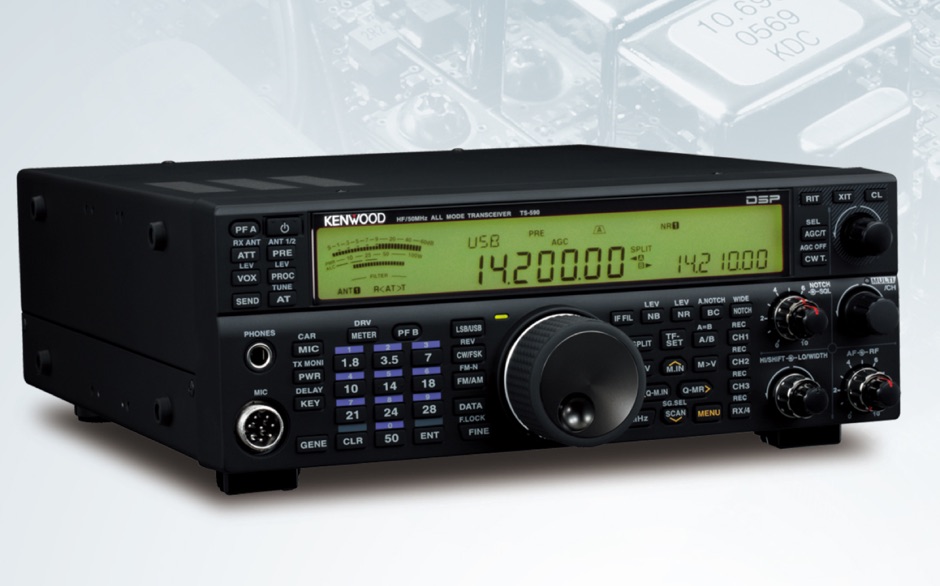 Step by step instructions for setting up N1MM Logger to communicate with the TS-590S using the USB connection
 -
 TAHO.EXE, an open-source software, facilitates the creation of APRS maps for _UI-View_ by converting free data from _OpenStreetMap_ into the required *.JPG and *.INF file formats. This utility, developed by Dimitri Junker with specific UI-View format support added at the request of HB9DTX, streamlines the process of integrating detailed geographical information into the _UI-View_ platform. It operates on Windows, generating map files with border coordinates in just a few clicks, eliminating the tedious manual creation of *.INF files for custom maps. This converter allows UI-View users to leverage the continuously updated and community-contributed data of OpenStreetMap, which often surpasses commercial map quality in specific regions. The process is straightforward, with a detailed step-by-step guide available on the OpenStreetMap wiki, translated into French and German. TAHO.EXE significantly enhances the utility of UI-View by providing a readily accessible and continuously improving source of detailed, current geographical maps for displaying APRS station positions and objects.
 -
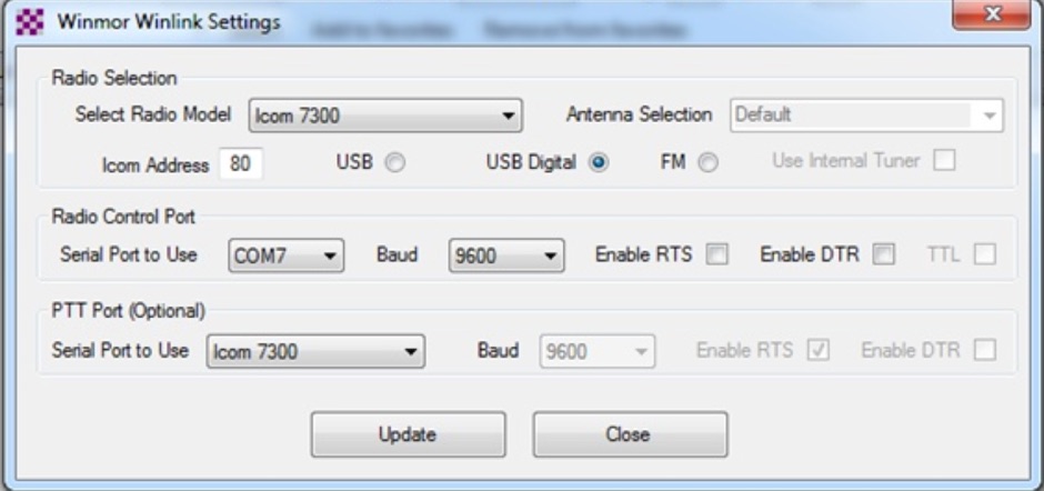 This tutorial provides step-by-step instructions for setting up the ICOM IC-7300 to work with WinLink and WinMor. The process begins with downloading the necessary USB driver from ICOM Japan, followed by configuring the radio settings through the menu. Key settings include selecting the correct output and data modes, as well as ensuring the USB serial function is properly set. Once the radio is connected to the PC via USB, the drivers will install automatically, allowing for seamless communication. After confirming the installation of the USB Audio CODEC and COM port, users are guided to download the RMS Client Software for WinLink. The tutorial emphasizes the importance of understanding the WinLink system and provides links to additional resources for setup. Finally, it details how to configure the WinMor modem settings, ensuring the ICOM IC-7300 is ready for effective digital communication. This guide is essential for operators looking to enhance their digital capabilities using the IC-7300.
 -
 The GM4JJJ VHF and EME pages document David's extensive work in Earth-Moon-Earth (EME) communication, specifically on the 144 MHz band, and his involvement in amateur radio astronomy. The resource details his station setup and operational experiences, providing insights into the technical challenges and rewards of bouncing signals off the moon. It offers a glimpse into the specialized equipment and techniques required for successful EME contacts, a niche but highly rewarding aspect of amateur radio. David's content shares practical applications and field results from his EME endeavors, which can be particularly useful for hams contemplating or actively pursuing moonbounce operations. The information, while not a step-by-step guide, implicitly compares the complexities of EME with more conventional VHF/UHF operations, highlighting the significant power and antenna gain necessary to overcome path losses. This resource serves as a testament to the advanced capabilities achievable in amateur radio.
 -
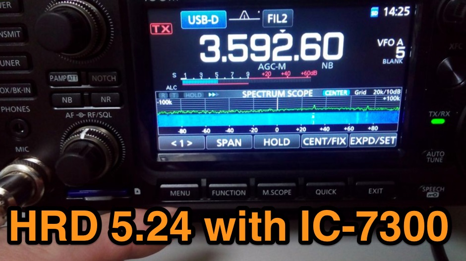 The Icom IC-7300 is a popular HF transceiver among amateur radio operators, known for its advanced features and ease of use. However, integrating it with software like Ham Radio Deluxe (HRD) can be challenging due to compatibility issues. This guide provides step-by-step instructions on how to configure the IC-7300 to work seamlessly with HRD 5.24, the last freeware version available. It covers the installation of necessary drivers, setting up virtual COM ports, and configuring audio settings for digital modes. To begin, users must download and install the Icom USB driver, which creates a virtual serial COM port for communication between the radio and the computer. The guide details how to check for this new port and adjust the CI-V address settings to ensure proper communication. It also explains how to set up the soundcard settings in HRD for digital modes, allowing operators to transmit and receive audio effectively. Following these instructions will enable IC-7300 owners to maximize their radio's capabilities with HRD.
 -
 The article details a specific method for performing maintenance on a crank-up tower, focusing on cable and rotator replacement without a full power pulldown. It outlines the necessary equipment, including a 2-section extension ladder with a horn attachment and a two-piece, 6-foot steel pipe, specifying a 1 1/4-inch diameter. The procedure involves lowering tower sections onto the internal pipe to slacken cables, allowing for their removal and replacement, and also describes how to replace the rotator while the tower remains upright. Key steps involve using the pipe to support tower sections, enabling access to the cables and bearings. The author, N5AR, emphasizes safety by instructing the reader to remain on the ladder at all times, rather than climbing the tower itself. The process is presented as manageable for a single operator, with the author having successfully completed the task on a _UST TX472_ tower. Specific tools mentioned include Allen wrenches and end wrenches for cable ends and bearing bolts. The method provides a practical approach for tower upkeep, minimizing the complexity often associated with such tasks and allowing for maintenance of components like cable pulleys and their bearings.
 -
 A system designed to automatically tune small transmitting magnetic loop antennas, particularly beneficial for **contest operations** where rapid frequency changes are common. The core of the system involves a PC-based control application, AutoCap, written in C#, which monitors antenna SWR via an external meter and commands a motor interface to adjust the loop's variable capacitor. The software is compatible with Windows and Linux via the Mono framework, offering a graphical user interface for monitoring system status, SWR, power, and motor commands. Key components include one or more magnetic loop antennas equipped with DC or stepper motors for capacitor adjustment, an SWR meter with data output (such as the Telepost LP-100A or a homebrew serial/USB SWR meter), the AutoCap PC software, and a motor interface. The most effective motor interface utilizes an **Arduino-based controller** with custom firmware, providing precise control over both simple DC motors and stepper motors, and supporting features like motor braking for finer adjustments. The system allows for configurable SWR thresholds, pulse widths, and motor effort settings to optimize tuning speed and resolution. Optional radio integration provides frequency hints, enabling the algorithm to learn the relationship between motor actions and resonant frequency, thereby speeding up initial tuning responses. The software also supports antenna profiles, allowing operators to save and recall specific configurations for different loops, including accumulated frequency hint data.
 -
 Pictures and description of a SteppIr vertical antenna setup in a small backyard using DX Engineering radial plates.
 -
 A 200 kHz bandwidth digital transmission system for image transfer in the Amateur Service is under development, specifically targeting VHF allocations. John B. Stephensen, KD6OZH, leads this project under an FCC Special Temporary Authority (STA) valid until September 10, 2006, authorizing emissions up to 200 kHz bandwidth in the 50.3-50.8 MHz segment. Current regulations typically limit bandwidths to 20 kHz on VHF amateur bands, making this STA crucial for testing wideband digital modes. The modem, a modified **OFDM** (Orthogonal Frequency Division Multiplexed) unit, was initially tested on the 70-cm band. It splits a high-rate data stream into multiple low-rate subcarriers to mitigate multipath echoes. The system uses a DCP-1 card with a Xilinx XC3S400 FPGA and Oki Semiconductor ML67Q5003 microcontroller. The transmitter, located at 36d 46m 30s N, 119d 46m 22s W, generates 150 WPEP into an 8 dBi gain vertical antenna, while the mobile receiver uses a Ham-stick. Three data formats for 50, 100, and 200 kHz channels are being tested, with encoded data rates of 96, 192, and 384 kbps. Verilog code for the VHF OFDM modem is 95% simulated, with modifications from the UHF version including increased filter coefficient precision and a change from Ungerboeck **TCM** to BICM for improved performance over fading paths. Final tests will involve one-way over-the-air measurements of bit error rates and coverage area.
 -
 Presents a construction project for a 1:1 current balun, specifically detailing the _Sorbie Balun and Bottle Choke_ design. The resource outlines the winding technique, employing 4+4 turns of mini coaxial cable on a large ferrite core, and provides insights into the physical assembly. It includes specific material recommendations, such as the type of ferrite and coaxial cable, crucial for achieving the desired impedance transformation and common-mode current suppression. The content covers the practical steps involved in building the balun, from preparing the coaxial cable to securing the windings on the ferrite toroid. It also discusses the integration of the balun into an antenna system, emphasizing its role in maintaining pattern integrity and reducing RF interference in the shack. The resource offers a clear, step-by-step approach, making the project accessible for homebrewers. Illustrations and photographs accompany the text, visually guiding the builder through each stage of construction. The article concludes with performance expectations and considerations for deployment, ensuring the constructed balun functions effectively across the intended frequency range.
 -
 The **TransWorld Antennas TW2010 Traveler HF Portable Vertical Antenna** assembly video provides a visual walkthrough for deploying this popular portable HF antenna. It details the step-by-step process, from unpacking components to final setup, which is crucial for operators preparing for field day operations or DXpeditions. The video focuses on practical aspects, showing how to connect the various elements and secure the antenna for optimal performance. Operators often seek clear assembly instructions for portable antennas like the TW2010 to ensure quick and correct deployment in diverse environments. This visual aid helps clarify potential ambiguities found in written manuals, illustrating the proper handling of the antenna's radial system and telescopic elements. The video serves as a valuable resource for those aiming to achieve efficient operation with the **TW2010 Traveler** in a portable setting. Understanding the assembly sequence can significantly reduce setup time and prevent common errors encountered during initial deployments.
 -
-
 Operating the AO-51 amateur radio satellite with a handheld transceiver (HT) presents a practical entry point for newcomers to satellite communications. This resource details the necessary steps and considerations for making basic contacts, focusing on accessible equipment. It covers fundamental concepts such as _Keplerian elements_ for satellite tracking and the importance of understanding Doppler shift effects on both uplink and downlink frequencies. The tutorial outlines a straightforward approach to satellite passes, emphasizing the use of readily available gear. It provides insights into antenna orientation and timing for successful two-way communication. The content aims to demystify satellite operation, enabling operators to achieve their first **AO-51** contacts with minimal specialized equipment. Key aspects include frequency management and basic operational techniques.
 -
 The VersaBeacon is a frequency agile, modulation agile RF source using a DDS chip and minimal support circuitry. It covers a frequency span of 1MHz to 150MHz in 1 Hz steps and provides a variety of modulations
 -
 A synthesized 2.3 GHz Amateur Television (ATV) transmitter design, conceived by Ian G6TVJ, is presented, targeting broadcast-quality video performance on the 13cm band and extending up to 2.6 GHz. The core of the design utilizes a commercial Z-comm Voltage Controlled Oscillator (VCO) that tunes from 2.2-2.7 GHz, providing a +10 dBm output and simplifying RF alignment. This VCO's stability, originally intended for narrowband applications, readily accepts high-frequency video modulation, contributing to the transmitter's robust performance. The exciter stage, incorporating a Mini Circuits VNA 25 MMIC amplifier, boosts the signal to +16dBm, while a Plessey SP4982 prescaler divides the output frequency for the synthesizer. The synthesizer employs a Motorola MC145151 CMOS parallel IC, favored over the common Plessey SP5060 for its superior video modulation characteristics and ease of programming without microprocessors. This choice addresses issues like LF tilt and distorted field syncs often seen with SP5060 designs, particularly when operating through repeaters or over long distances. The MC145151 divides the signal further, enabling precise frequency stepping, with programming handled by EPROMs for channel selection and LED display. The loop filter network, critical for video integrity, was developed through experimentation to prevent the PLL from reacting to video modulation, ensuring a clean transmitted picture. The transmitter incorporates a Down East Microwave commercial power amplifier module, delivering approximately 1.6W output, driven by the exciter through a 3dB attenuator. Construction involves surface-mount SHF components on micro-strip lines etched onto double-sided fiberglass board, housed within a tinplate box. The design boasts no AC coupling in the video path, preserving low-frequency response, a common failing in other ATV transmitters. Performance tests with a 50Hz square wave revealed no LF distortion, and a calibrated "Pulse & Bar" signal showed a near 100% HF response, demonstrating its capability for high-quality ATV transmissions.
 -
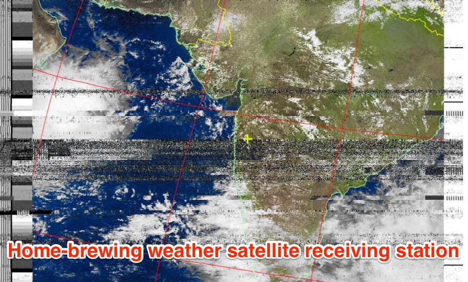 The page provides a detailed guide on how to build your own NOAA weather satellite receiving station, covering hardware, antenna, computer setup, and software installation. It offers a straightforward explanation suitable for beginners and serves as an educational project. The content includes step-by-step instructions and tips for observing satellites in the night sky.
 -
 Mobile RFI, often manifesting as persistent noise in the receiver even with the antenna disconnected, frequently originates from the vehicle's power supply system. This guide details systematic troubleshooting steps, beginning with isolating the radio from the car's 12-volt supply to confirm the power system as the noise source. It emphasizes the critical importance of drawing power directly from the battery using **heavy gauge wire**, bypassing the fuse block to leverage the battery's natural capacitance for RFI suppression and ensuring a solid RF ground. Proper routing of power lines through the firewall is also covered, advocating for dedicated grommeted holes to prevent inductive coupling from other wiring harnesses. The article stresses the necessity of fusing both positive and negative leads from the battery, a crucial safety measure to prevent damage to the rig and mitigate high-current risks should the battery's engine block ground become compromised during service. Addressing **alternator whine**, a common high-pitched noise that varies with engine speed, the resource suggests checking battery connections and the alternator-to-battery harness for looseness or corrosion. It also mentions the utility of adding an external RF noise suppression capacitor in parallel with the alternator's internal capacitor for enhanced filtering, and the effectiveness of commercially available in-line power supply filters.
 -
 The AT-AUTO automatic antenna tuner handles 1.5kW CW operation, employing stepper motors under microprocessor control to precisely position a roller inductor and air-dielectric variable capacitor, avoiding relay-switched discrete components. This design choice prevents loud relay clacking and burning contacts, a common issue with competing products. The tuner features auto-retuning capabilities and receives periodic firmware updates, ensuring continuous improvement and added user-requested features. Its companion product, the _CX-AUTO_ coaxial switch, also features an embedded microprocessor controller. It enables selection of 1-of-8 coaxial outputs via a serial data interface. When integrated with the _AT-AUTO_, the tuner can associate specific coaxial outputs with amateur radio bands, automatically commanding the _CX-AUTO_ to select the correct antenna when the operator QSYs to a different band. Don Kessler began designing the AT-AUTO in 2005, with its debut at the 2006 Dayton Hamvention. Kessler Engineering also offers custom RF product design and electrical engineering consulting, specializing in Class-E RF amplifiers.
 -
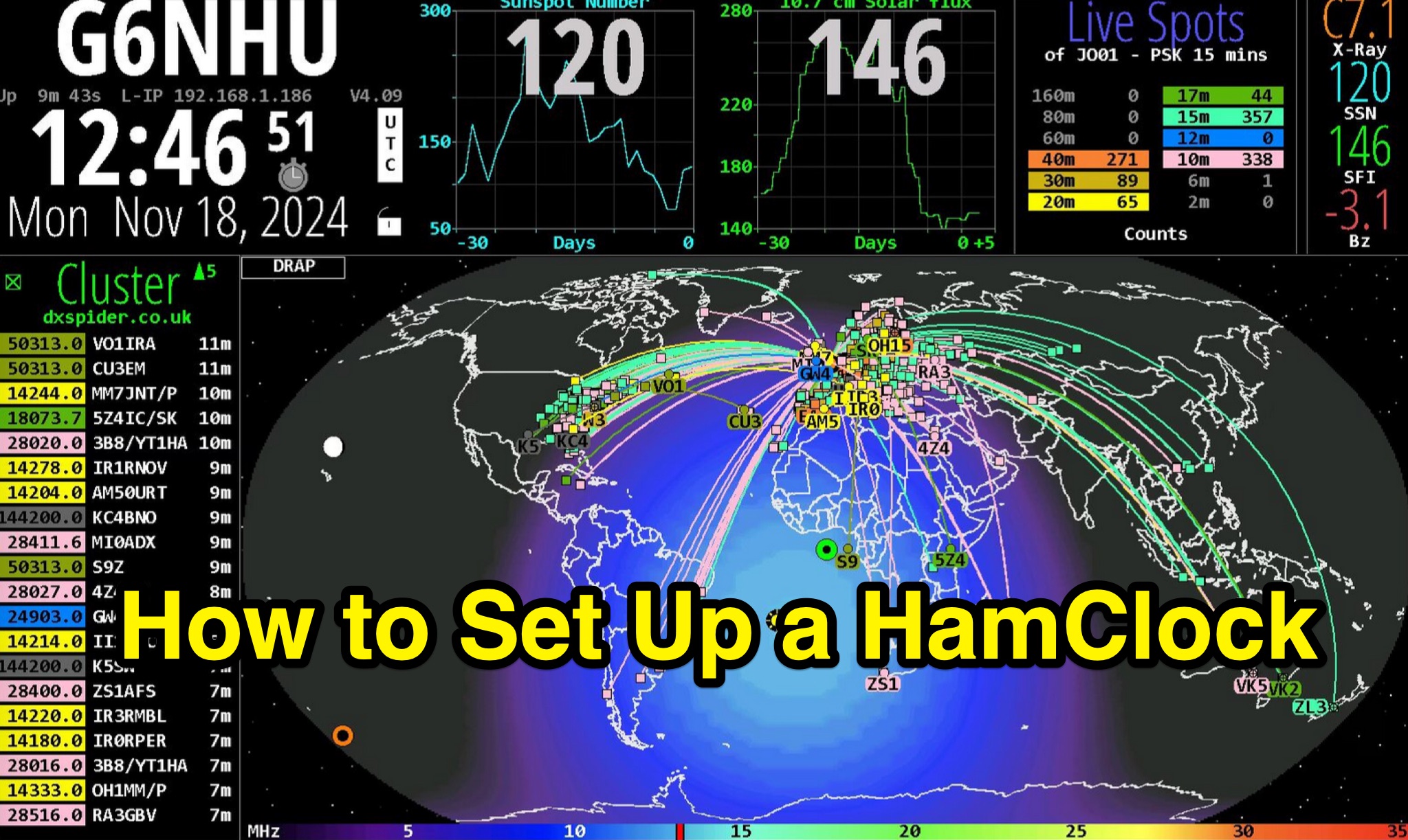 This detailed guide provides step-by-step instructions on setting up a HamClock for your shack using a Raspberry Pi and the HamClock 4.21 software. It includes recommendations for hardware such as Raspberry Pi models, SD cards, PSUs, and displays. The guide covers installation, setup, configuration, and suggestions for customizing the default settings. Whether you are a beginner or experienced ham radio operator, this guide will help you create a functional HamClock for your shack with ease.
 -

-
 Installing a mobile rig in a vehicle requires careful planning and execution to ensure optimal performance and safety. The process begins with selecting the right equipment, such as the ICOM IC706MKII for low bands and the ALINCO DR-610 for VHF/UHF operations. Proper mounting is crucial; both radios are strategically placed under the back seat of the Silverado, allowing for a clean installation while maintaining passenger comfort. The Hustler antenna, equipped with various resonators, ensures coverage across multiple bands, while the LDG automatic antenna tuner fine-tunes the match for efficient operation. A remote head for the tuner enhances accessibility, making adjustments easier while driving. Each step of the installation is documented to provide insights and tips for fellow operators looking to enhance their mobile setup. The experience shared here reflects practical knowledge gained through hands-on work, aiming to inspire others in the ham community to undertake similar projects.
 -
 Constructing a high-performance RF spectrum analyzer up to 1000 MHz requires careful attention to component selection, shielding, and circuit isolation. This resource details a project that improves upon the _Spectrum Analyzer for the Radio Amateur_ design by Wes Hayward (W7ZOI) and Terry White (K7TAU), incorporating ideas from Scotty Sprowls' project, particularly his 1013.3 MHz IF bandpass cavity filter. The analyzer utilizes a Mini-Circuits SRA-11 mixer with a sweeping local oscillator from 1013 to 2013 MHz, feeding into a 4-pole copper pipe cavity filter. The design employs a second SRA-11 mixer with a fixed 1024 MHz LO to produce a 10.7 MHz final IF. This signal then passes through narrowband resolution filters and is processed by Analog Devices AD603 and AD8307 ICs for IF amplification and logarithmic detection, driving an oscilloscope in X/Y mode. The project emphasizes modular construction, using salvaged components and double-sided FR4 material for PCBs, with critical notes on minimizing spurious images through effective shielding and proper voltage regulation for each module. Key components include a Z-Communications V585ME48 VCO for the first LO and a Z-Comm V583ME01 VCO controlled by a Motorola MC145151 PLL for the second LO. An optional Hittite HMC307 step attenuator and K&L 5L121-1000/T5000-O/O low-pass filter manage RF input. Tuning procedures for the 10.7 MHz IF resolution filter are also detailed, showing before-and-after spectrum views.
 -
 This resource is an online tutorial focused on setting up the Raspberry Pi for amateur radio applications. It covers the installation and configuration of various software packages tailored for digital communications and protocols, including _Packet Radio_ with Hamlib and Direwolf, as well as data modes like FLDigi and WSJT-X. The guide also details the integration of hardware components such as GPS clocks for time synchronization and real-time clocks for enhanced functionality. Users will find instructions for installing software like GPredict for satellite tracking and GQRX for software-defined radio (SDR) applications. The tutorial emphasizes practical steps, including the use of command-line inputs in the Raspberry Pi OS terminal, and provides troubleshooting tips for common issues such as faulty SD cards or insufficient power supplies. Operators are encouraged to explore various applications, including APRS iGates and WSPR beacons, to enhance their ham radio experience. The material is designed for licensed amateur radio operators with basic knowledge of electronics and computing.
 -
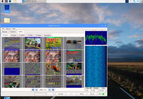 A tutorial on how to setup a receiver capable to decode SSTV signals with a small RaspberryPi version 2 and a RTL-SDR dongle. The author explains how to install the needed software to interface the RTL-SDR and a step by step guide to install the QSSTV software used to decode the signals.
 -
 Presents _Beam Quest_, the official Japanese distributor for _SteppIR_ antennas, detailing their product lineup and services. The site showcases various _SteppIR_ Yagi models, including the _Dream Beam_ series (DB42, DB36, DB18E, DB11) with configurations from two to four elements, alongside the _Big IR_ and _Small IR_ vertical antennas. It also lists accessories such as TX/RX and PC interfaces, essential for integrating these advanced antenna systems into a ham shack. Operators often seek out _SteppIR_ antennas for their dynamically adjustable element lengths, which allow for optimization across multiple bands, a significant advantage for DXing and contesting. This adaptability contrasts sharply with fixed-element Yagis, providing a distinct edge in varying band conditions. The resource provides contact information, including email and phone numbers, for inquiries and support regarding _SteppIR_ products within Japan, serving as a direct point of contact for sales and technical assistance.
 -
 Six Steps for Programming your IC-2100H from the front panel of radio. Using these steps you should have no trouble entering either simplex or repeater frequencies and saving them.
 -
 Presents the full owner's manual for the _Drake R-4C_ communications receiver, specifically a late version edition. This resource outlines the comprehensive operational instructions, covering everything from initial setup and tuning to advanced features and controls. Hams can reference detailed diagrams and explanations for proper signal reception across various amateur bands. The manual includes critical information for alignment procedures, ensuring the receiver performs to its optimal specifications. It details the steps required for calibrating the internal circuitry, which is essential for maintaining sensitivity and selectivity over time. My experience with vintage Drake gear confirms the value of these original documents for accurate adjustments. Furthermore, the document provides insights into troubleshooting common issues and performing routine maintenance. It serves as an authoritative guide for anyone operating or servicing this classic piece of amateur radio equipment, helping to preserve its functionality for years of DXing and ragchewing.
 -
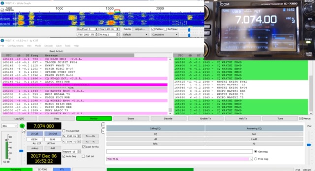 The _Icom IC-7300_ transceiver, a popular SDR rig, can be readily configured for digital modes like FT8 using _WSJT-X_ software. This guide details the necessary steps, from downloading the correct version of WSJT-X to configuring the radio's USB audio and CAT control settings. It emphasizes a straightforward approach, aiming to simplify the often complex initial setup for new digital mode operators. K0PIR shares his practical experience, outlining the specific menu settings on the IC-7300, such as USB SEND/DPT and USB MOD LEVEL, which are crucial for proper signal modulation and transmission. The resource also covers the integration of WSJT-X's built-in logging capabilities, streamlining the process of recording digital contacts without needing external logging software immediately. This setup allows for efficient operation on various HF bands. Two embedded videos further illustrate the configuration process, providing visual aids for each step, from initial software installation to making the first FT8 contact. The author's method focuses on minimizing common setup hurdles.
 -
 Sell quality electronic components, equipment, and accessories. Test equipment, RF Modules, Power supplies, PCB, Stepper motors.
 -
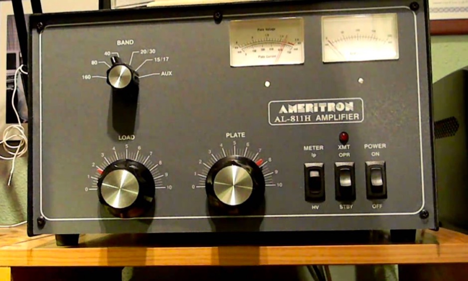 Easiest possible tuning steps using a closed CW key, FM or AM tuning the Ameritron AL-811H