Search results
Query: ground for antennas
Links: 101 | Categories: 3
-
 Designing and constructing portable wire antennas for HF operations, this resource explores several configurations including the _foldback dipole_ for space-constrained setups and an inductively shortened dual-band dipole for 20m and 40m. It details the calculation of inductance for shortened elements, providing a Visual Basic 6.0 program screenshot that illustrates determining coil parameters like turns and length for a **25.5 uH** inductor. The document emphasizes practical considerations such as adjusting wire lengths for optimal SWR, noting that a dual-band dipole achieved SWR below 2:1 on both 20m and 40m, with careful adjustment bringing it under 1.5:1. Further, the resource describes a half-wave antenna matched with a coaxial stub, a method often referred to as the _Fuchskreis_ in German amateur radio circles, to transform the high feedpoint impedance to 50 Ohms. This monoband solution, for a 20m application, uses a stub length of **2.98m** (0.216 lambda multiplied by coax velocity factor) and a shorted stub of approximately 48cm. The coaxial stub design is highlighted for its resilience to ground proximity, allowing it to be rolled up or laid on the ground with minimal SWR impact, making it highly suitable for portable QRP operations.
 -
 The 160 meter ground plane is constructed from #10 stranded insulated wire available in most hardware stores. The feedpoints / tiepoints use PVC pipe T-sections Article by W1TR
 -
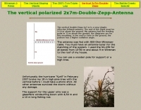 The vertical Double-Zepp 2x7 m is a very simple, effective 8-Band-antenna. The end of the Dipol must be 5-10 m above the ground
 -
 Operating a ham station often involves encountering radio frequency interference (RFI), RF feedback, or RF burns, which are frequently misattributed to poor equipment grounding. This resource meticulously dissects these assumptions, asserting that RF grounds on the operating desk often merely mask more significant system flaws. It identifies five primary causes for RF problems, including antenna system design flaws, proximity of the antenna to the operating position, DC power supply ground loops, equipment design defects, and poorly installed connectors or defective cables. The content emphasizes that issues like "hot cabinets" or changes in SWR when connecting a ground indicate substantial RF flowing over wiring or cabinets, a phenomenon known as common-mode current. The article provides detailed explanations of common-mode current generation, particularly from single-wire fed antennas like longwires, random wires, and OCF dipoles, which inherently present high levels of RF in the shack. It also illustrates how vertical antennas, lacking a perfect ground system, can excite feed lines with significant common-mode current. Through simulations, the author demonstrates how a dipole without a proper _balun_ can cause RF problems at the operating desk, showing current patterns and voltage distributions on feed line shields. The discussion extends to the proper application of _RF isolators_ and _ferrite beads_, clarifying their role in modifying common-mode impedance on cable shields and cautioning against their use as a band-aid for fundamental system defects. The resource advocates for correcting the actual source of RF problems, such as antenna system issues or poor connector mounting, rather than relying on internal shack grounding or isolators. It highlights that properly functioning two-conductor feed lines, like coaxial or open-wire lines, should result in minimal RF levels at the operating position, even without a desk RF ground. The author shares personal experience, noting that his stations since the late 1970s have operated without RF grounds at the desks, relying instead on proper antenna system design and feed line integrity.
 -
 The Superantennas MP-1 portable HF antenna is analyzed for its design and field performance, particularly its high-Q loading coil and 3/8-inch mounting. The review details the antenna's construction, including an 8-inch vertical section, a large-diameter loading coil tuned by a sleeve, and a 4-foot whip that disassembles into six rods for transport. Initial testing with the supplied 10-foot ribbon cable "ground plane" yielded poor SWR and RF hot conditions, indicating an inadequate ground system. Further experimentation with longer radials and resonant counterpoises for each band improved matching and eliminated RF hot issues, but introduced significant operational complexity. The author notes the difficulty in optimizing both counterpoise length and coil setting without an antenna analyzer, and the sensitivity of the MP-1 to counterpoise deployment. The review also discusses the recommendation to tune for maximum received signals rather than minimum SWR, often necessitating an external ATU due to the antenna's typical low impedance. The **MP-1**'s critical dependence on resonant counterpoises for effective operation, especially when elevated, is highlighted as a major drawback for portable use. The author ultimately sold the antenna, concluding that despite its sound technical design, its fussy nature and the need for extensive counterpoise management or an ATU detract from its portability and convenience compared to simpler, less expensive dipole solutions. The **Superantennas MP-1** is deemed a flawed portable antenna, requiring considerable effort to achieve its claimed performance.
 -
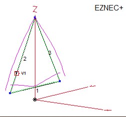
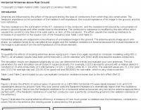 Antennas are influenced by the effect of the ground and by the type of conductors from which they are constructed. Effects of various types of grounds on a 1.825 MHz horizontal 0.5 wave dipole
 -
 How manage and quantify ground loss in vertically-polarized antennas by VE3VN
 -
 Presentation about Practical Antenna Modeling Using the NEC Codes with examples of HF wire antennas and 4NEC2. How to define and edit the models, Running the simulations, Work some examples, Variables usage, Deal with Feed Lines and ground
 -
 Relevance of a proper ground systems on short HF vertical antennas, with an analysis on a vertical antenna for 160 meter band
 -
 Presents field test results for an **elevated SuperAntenna MP-1** portable antenna, configured on a tripod for HF operations. The resource details the antenna's setup and performance during a portable activation, focusing on its use across the 40-meter, 20-meter, and 17-meter amateur bands. It includes observations on signal reports and operational considerations for this specific portable antenna configuration. The content provides practical insights into deploying the MP-1 antenna in a non-ground-mounted setup, which is often a point of interest for portable and QRP operators. It documents the author's experience with the antenna's tuning and effectiveness for making contacts under real-world conditions, offering a user-perspective review of its capabilities. The article also features photographic evidence of the antenna's deployment, illustrating the tripod mounting and the overall portable station setup.
 -
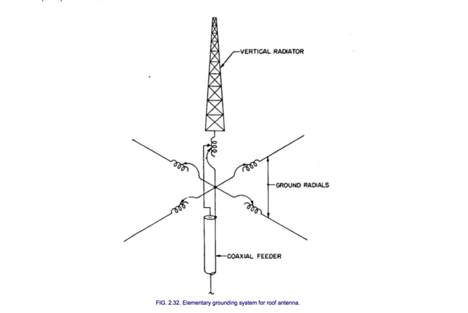 When a broadcast antenna is to be placed on top of a building, there are special problems of feeding and grounding. The radiator is usually electrically short, that is, much less than one-quarter wavelength high.
 -
 Designing and constructing a two-element receiving loop antenna array for HF operation involves specific considerations for achieving high directivity and noise reduction. This resource details a homebrew system comprising two 30-inch diamond-shaped loops, spaced 20 feet apart, which are fed through mast-mounted preamplifiers and passive signal combiners. The operational principle relies on adjusting phase delays between elements via precise _Belden 8241_ coaxial cable lengths, optimized for specific bands from 160m to 20m. Performance data, derived from _EZ-NEC_ modeling, illustrates consistent 90° azimuth-plane beamwidth and low take-off angles across the target bands, with _Receiving Directivity Factor_ (RDF) values comparable to a 300-foot Beverage antenna. The article presents detailed elevation and azimuth plots for 20m, 30m, 40m, 80m, and 160m, demonstrating the array's ability to provide strong response at low DX angles while also supporting _NVIS_ signals. Key components like the _DX Engineering RPA-1_ preamplifier and _DXE RSC-2_ signal combiner are discussed, alongside the importance of impedance matching to preserve antenna patterns. The construction emphasizes self-contained elements that do not require ground radials, offering a compact solution suitable for suburban environments and stealth installations, with a focus on optimizing receive performance independently from transmit antennas.
 -
 Tecom industries product line encompasses a wide range of highly sensitive active and passive antennas for use in airborne and ground applications, providing complete coverage of the 20 MHz to 40 GHz frequency range.
 -
 The resource, "Conventional Use of Transmission Line," meticulously details the operational principles of transmission lines, emphasizing the Transverse Electromagnetic (TEM) mode of energy transfer. It clarifies that for a line to function purely as a transmission line, all currents must be confined internally, with external fields ideally zero. The discussion differentiates between balanced and unbalanced lines, asserting that while both require equal and opposite currents within the conductors, the key distinction lies in the voltage relationship of each conductor to the surrounding environment. It highlights that a good antenna pattern does not inherently confirm proper feeder balance, and that common-mode currents can lead to RF in the shack and increased noise levels, even without pattern distortion. The article further explains that a transmission line can become a radiating conductor if energy is applied in a non-TEM mode, leading to common-mode issues. It cites classic texts like Jordan and Balmain's "_Electromagnetic Waves and Radiating Systems_" and Kraus's "_Antennas_" to support its definitions of TEM mode operation. The content also explores non-transmission line applications of parallel or concentric conductors, such as _coaxial dipoles_ and _folded dipoles_, which intentionally operate in non-TEM modes for antenna functionality. The author, _W8JI_, stresses that simply measuring equal currents is insufficient to confirm a balanced feeder; phase and voltage balance to ground are equally critical.
 -
 AN-SOF is a professional comprehensive software tool for the modeling and simulation of antenna systems. AS-SOF allows to describe antenna geometry, Choose construction materials, Describe the environment and ground conditions, Describe the antenna height above ground, Analize radiation pattern and front-to-back ratio, Plot directivity and gain, Analize input impedance and VSWR,Predict antenna bandwidth
 -
 Operating an amateur radio club, VE2CEV details its activities, including regular meetings and a significant project involving the construction of a **satellite ground station**. The resource outlines the project's inception, team formation, equipment acquisition, and the physical installation of antennas and rotator systems. It specifically mentions the use of a dual-axis AZ/EL rotator and antennas for VHF, UHF, and SHF (2 meters, 70 centimeters, and 13 centimeters), along with the strategic use of **Heliax cables** to minimize RF signal loss. The club also provides information on its interconnected repeater network covering southwestern Montérégie. The content highlights the practical application of the satellite station for communicating via amateur satellites and the International Space Station (ISS). It details the collaborative effort of members in securing a powerful Linux server, negotiating antenna installation with local authorities, and the precise alignment of antennas. The club emphasizes its role in guiding new amateurs, offering demonstrations, and potentially organizing courses, indicating a focus on community engagement and technical education within the amateur radio hobby.
 -
 Efficient Low Band Counterpoise for Restricted Circumstances Loss Avoidance Opportunities and Techniques for the Low Bands The short and linear FCP was designed to reduce ground losses from inadequate radial systems beneath inverted L and other vertical antennas.
 -
 The Terminated End Fed Vee Antenna (TEFV) is a travelling wave antenna with constant current distribution. Unlike traditional resonant antennas, TEFV operates without standing waves, using a terminating resistor for broadband efficiency. With a combination of vertical and horizontal polarization, it offers wide bandwidth from 1.8 MHz to 30 MHz, eliminating the need for a tuner. Key components include a 9:1 unun transformer and a 500-ohm terminating resistor. Grounding and counterpoise enhance performance, and it can handle power losses of up to 30%. TEFV provides an effective, versatile antenna solution for amateur radio and broadcast applications.
 -
 A balun is a MUST for dipoles or similar antennas when they are feed with coaxial cable. From the RF point of view, the shield can be modeled as two conductors, the internal shield (the real shield, this is, ground) and the external shield, who is really far to be ground. In this way, your dipole has 3 arms, the two from the dipole and the coaxial cable shield (external face)
 -
 The antenna ground or earth system can be key to its operation whilst also being a key safety feature. This article is about grounding systems for antennas, covering different aspects of grounds made for antenna safety, or expressly for lightning or just to improve antenna performance, being ground an antenna component.
 -
 In this post by N6CTA, discover the conversion of the Yaesu ATAS-120A screwdriver antenna for portable use. The author details the creation of two sets of radials, 16 and 32 in 16ft lengths, aiming to optimize the efficiency of ground-mounted antennas. Additionally, insights are shared on attaching male quick disconnect blade tabs, with potential plans for a radial plate kit.
 -
 Operating in antenna-restricted communities presents unique challenges for amateur radio operators, often necessitating creative solutions for antenna deployment. This resource details the design and implementation of stealth antennas within a townhouse community in Exton, PA, where external antennas were strictly forbidden by covenants. The author, WB5NHL, describes his setup, which involved locating the shack in the basement and utilizing an unused space under the roofline of a finished third-floor loft for antenna placement. The content specifically addresses the practicalities of routing coax cables three floors and maximizing antenna performance within limited attic space. It covers solutions for multi-band operation, including dedicated sections for 40-10 meter and 80-meter antennas, along with strategies for mitigating potential interference issues. The approach emphasizes full compliance with community covenants, achieving maximum height-above-ground for horizontal antennas, enabling instant band switching, and efficiently utilizing available attic volume. While acknowledging limitations such as potential interference with high power and fixed antenna patterns, the resource provides a detailed account of a functional compromise for restricted environments. Links to individual pages on _coax cables_, _40-10 meter antennas_, _80-meter antennas_, and _interference issues_ offer deeper dives into each specific aspect of the installation.
 -
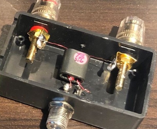
 This page describes a couple of parts box medicine bottle antennas that you can build. The ground side of the capacitor is soldered to the ground of the BNC connector. The positive side of the capacitor takes 5 turns around the toroid and is soldered back to itself. The center pin of the BNC connector takes 5 turns around the toroid and then continues on to the wire wound inductor. From there the antenna continues with an attached piece of wire.
 -
 Mounting on roof at the right ground level can greately impact on antenna performances because will affect the radiated angle of energy.
 -
 The _G3TSO_ Mobile Antenna Page details construction and tuning methods for mobile antennas operating across **10 to 160 metres**. The content describes a Hustler-based design, optimized for RF performance and vehicle speeds, featuring centre loading. For optimal operation on various bands, the loading coil placement requires clearance from the vehicle body. Antenna resonance is critical for efficient mobile operation. A mobile antenna's base impedance may be as low as 27 ohms, requiring specific matching to achieve maximum radiation, as a minimum SWR at the transmitter does not always indicate resonance or maximum output. Tuning involves physical adjustment of antenna length to achieve resonance at the operating frequency. The _G3TSO_ page outlines a tuning procedure utilizing a low-power signal source and a field strength meter to identify maximum radiation before impedance matching. Loading coil placement, either at the base, center, or top of the antenna, influences radiation efficiency and mechanical stability for mobile installations. Centre-loaded whips, such as the Hustler design, offer a compromise between efficiency and stability, often for single-band operation. Helically wound antennas, including those for **28 MHz**, may present base impedances around 17 ohms, resulting in a 3:1 SWR at resonance. Low resistance grounding at the antenna base is also specified for optimizing performance and minimizing RFI during mobile operation. DXZone Focus: Mobile | Any | Antenna Tuning | HF
 -
 An Inverted-L with its long leg sloping to the ground. It will still work very good, even if the horizontal wire has to be sloped diagonally to the ground, as long as you have enough horizontal space to keep it at about a 45 degree angle or more from the pole.
 -
 The 80-meter Skyloop antenna, a top-performing HF antenna, excels in weak signal work, low-noise operation, and omnidirectional coverage. Ideal for fixed stations, it delivers strong performance at low power, outperforming many alternatives, including 80m half-wave end-fed antennas. Requiring significant space for deployment, it’s well-suited for NVIS and groundwave use. Though not portable, it’s cost-effective and durable, with minor maintenance needs. Tuning may require adjustments for optimal resonance. It’s a standout for base stations, though a lighter portable version could enhance its versatility.
 -
 Modeling an antenna over real terrain gives you a visual picture of how terrain impacts performance. You can use a model to determine optimum height for antennas on an existing tower, Compare different tower locations for performance, Compare different sites for performance
 -
 This document details the construction of a multi-band end-fed antenna, suitable for situations with limited space for larger antennas. The design utilizes a 1:49 to 1:60 impedance transformer to match a half-wave wire antenna fed at one end. Compared to a traditional dipole, this antenna resembles a highly unbalanced Windom antenna with one very long leg and a virtual short leg. The design eliminates the need for radials but relies on the coax cable shield for grounding. The document recommends using at least 10 meters of coax and installing a common mode filter at the entry point to the shack for improved performance.
 -
 Steve Nichols, G0KYA, presents a practical examination of ground systems for vertical antennas, drawing heavily on the empirical research of Rudy Severns, N6LF. He explains that a robust radial field is crucial for ground-dependent verticals, effectively replacing the antenna's "missing half" and mitigating severe RF absorption in lossy soil. Nichols clarifies that surface radials do not strictly require a quarter-wavelength; instead, deploying a minimum of 16 to 32 shorter wires often yields superior results compared to fewer, longer ones. The presentation also addresses the common SWR paradox: a poor ground might show a perfect 1:1 match, but adding radials, while potentially raising the SWR to around 1.4:1, significantly improves true radiation efficiency. Nichols defines counterpoises as elevated wire networks that substitute for earth connections, offering solutions for limited-space installations, such as the **Folded Counterpoise (FCP)** for 160 meters. This resource provides actionable engineering data for optimizing vertical antenna performance.
 -
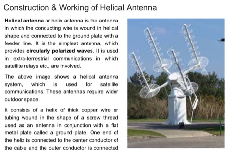 Helical antenna or helix antenna is the antenna in which the conducting wire is wound in helical shape and connected to the ground plate with a feeder line. It is the simplest antenna, which provides circularly polarized waves.
 -
 Operating from Banana Island, Sierra Leone (AF-037), the 9L2019 DXpedition by F6KOP and a ten-operator team used the callsign 9LY1JM from January 9-21, 2019. This detailed report covers the logistical challenges, including securing visas and licenses with local assistance from Mark 9L1YXJ and Gregory of Dalton’s Guest House. The team deployed monoband quarter-wave verticals on the beach and two Beverage on Ground (BOG) antennas for Europe/Asia and the USA, operating four stations simultaneously. Technical hurdles encountered included high tides submerging antennas, requiring repositioning, and persistent QRM between closely spaced stations, mitigated by doubling filters. CW signal irregularities at 30-32 WPM were resolved by PC and WINTEST restarts. A significant FT8 logging bug was identified and corrected with on-site software. Despite these issues, the team logged over 4,000 QSOs in the first 24 hours, averaging 5,000 QSOs daily, with a peak of over 6,000 in one day. Propagation varied, with excellent 160m conditions on January 12 yielding over 750 QSOs, and a later four-hour opening pushing the 160m total past 1,600. High bands were challenging due to low solar activity, but mid-bands provided intense pileups and rapid continent-wide contacts. The DXpedition concluded with nearly 50,000 QSOs, including a successful school QSO with Collège Doisneau de Sarralbe (57), managed by F1ULQ and F6KFT.
 -
 This project details the construction of a compact, circularly polarized Quadrifilar Helix Antenna (QHA) designed for 146 MHz operation. The antenna features a 1/2λ1/2λ helical design with a 2.6:1 aspect ratio, providing 4.5 dB gain and a spheroid radiation pattern. It is ground plane independent and compatible with both vertical and horizontal polarizations, making it ideal for terrestrial and space communications. The design includes step-by-step instructions for building the antenna using readily available materials like aluminum rods, PVC pipes, and RG-58 coaxial cable. The antenna's performance has been validated through comparisons with commercial omnidirectional antennas, showing superior results.
 -
 A homemade quarter wave ground plane anntenna for 4 meters band.
 -
 A 5/8 λ antenna, often thought to be ideal for all frequencies, has unique characteristics that don't universally apply. First introduced for medium-wave radio, it works optimally at 225° antenna length over ideal ground, yielding high efficiency. However, at VHF and higher frequencies, it offers no advantage over other antennas due to real ground conditions and complex matching requirements. DIY calculators provide only rough estimates, useful as a starting point for simulations, not for precise builds.
 -
 This page provides information on designing a lightweight Moxon antenna for the upper HF bands and VHF. The Moxon antenna is a compact version of a 2-element Yagi with folded elements, offering good forward gain and a high front-to-back ratio. It is designed for a single band with a feed-point impedance close to 50 ohms. Hams can orient the antenna horizontally or vertically, with polarization following the configuration, affecting radiation patterns. The page allows users to generate radiation pattern plots, VSWR charts, antenna currents diagrams, and Smith charts for their antennas on different ground types, helping them understand antenna performance in the field.
 -
 This page allows hams to design a vertical-plane delta-loop antenna for a single amateur HF band in different configurations. By choosing different feed-point positions, operators can observe variations in polarization properties, radiation patterns, and feed-point impedances. Users can generate radiation pattern plots, VSWR charts, antenna current diagrams, and Smith charts for their antennas over various ground types. Through adjusting the antenna's physical dimensions and refreshing the plots, hams can gain insights into the antenna's performance in the field. The page also discusses how elevation radiation patterns may change based on the antenna configuration and feed-point position.
 -
 Antenna patterns are all about interference. Presentation on wire antennas for HF bands. Dipoles, horizontal and vertical dipoles, effects of ground on radiation patterns, multi-band wires antennas. Knowing what you should expect from the radiation patterns for waves on your wires will help you choose what will work best for your needs. The principles of interference can lend insight into what to expect from a wire antenna.
 -
 The most basic form of repeater receives communication on one frequency and re-transmits it on a different frequency, a process known as duplex communication. This capability significantly extends the range of handheld and mobile radios, as repeaters are typically situated at elevated locations with high-gain antennas and greater transmit power. Repeaters commonly operate with FM modulation on the VHF (30 MHz – 300 MHz) and UHF (300 MHz – 3 GHz) amateur bands, which are ideal for portable and mobile devices. Access to repeaters is often controlled by a CTCSS or PL tone, an inaudible signal that prevents the repeater from retransmitting background noise. This mechanism ensures efficient use of the frequency and prevents illegal continuous transmission. Canadian regulations, for instance, require an Advanced amateur radio license and an available frequency within the band to set up a repeater, each assigned a unique call sign and transmit frequency. Configuring a radio for repeater use involves knowing the repeater's transmit frequency, its receive frequency offset (e.g., -600 KHz for VHF or +5 MHz for UHF), and the necessary CTCSS tone. The article references resources like Repeater Book for locating repeaters and provides practical examples for initiating and concluding a basic repeater session, emphasizing clear identification and concise communication.
 -
 Building some proper matching transformer for loop on ground and Beverage antennas
 -
 WB5NHL describes setting up a 160-meter antenna on a small suburban lot, where standard options like Beverage antennas and 1/4 wavelength verticals require extensive space and ground systems. Instead, Guy Olinger's Folded Counterpoise (FCP) provides a solution. The FCP minimizes ground losses by using a folded wire design, allowing effective antenna placement in limited space. The FCP, fed with an isolation transformer, enabled WB5NHL's first 160-meter antenna installation, offering improved performance despite space constraints.
 -
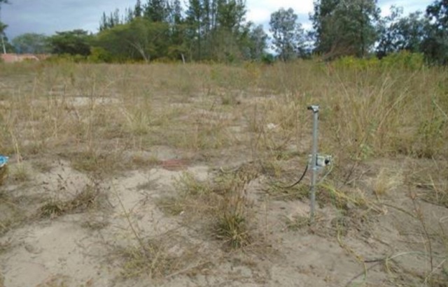
 The Beverage on Ground (BOG) antenna offers ham radio operators a compact alternative to traditional Beverage antennas, requiring less space and fewer support structures. This implementation, optimized for 1.8-7 MHz bands, describes ideal parameters: lengths of 60-90 meters, height of 2-10 cm above ground, and specific load resistances based on configuration. The article details experimental methods for determining optimal load resistance and presents matching systems to convert BOG impedance to 50 ohms. While less effective than classic 200-300 meter Beverages, the BOG provides directional reception in limited space, though performance varies with ground conditions and weather changes.
 -
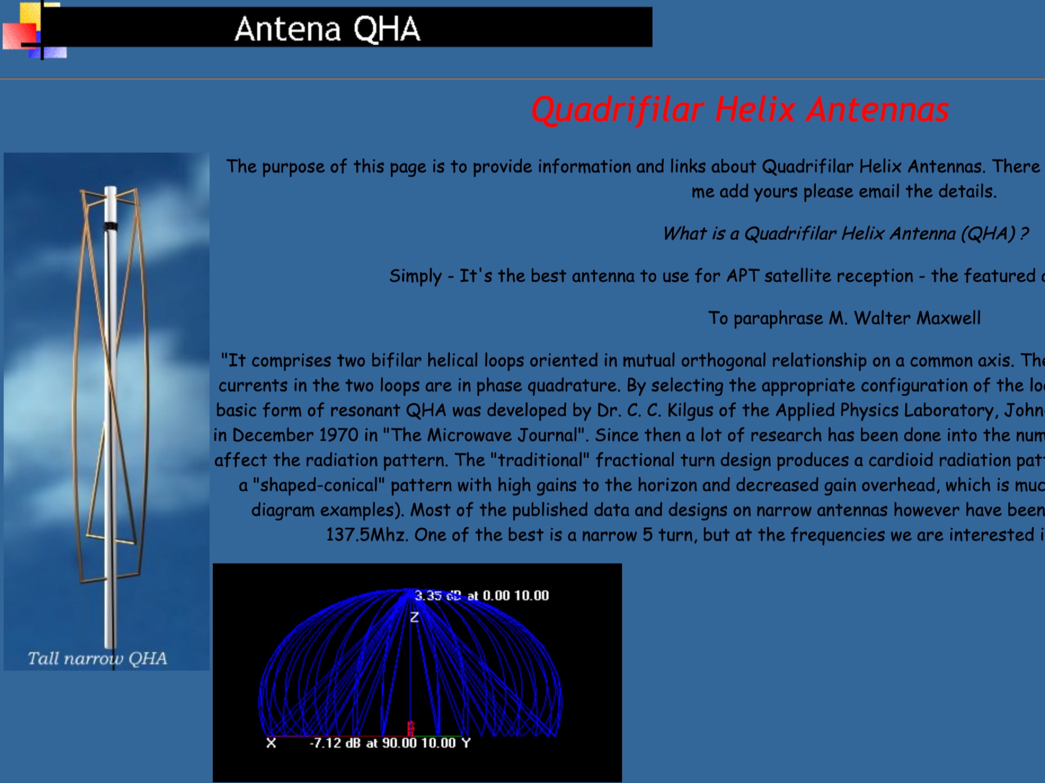 This page provides information and links about Quadrifilar Helix Antennas, the best antenna for APT satellite reception. It explains the basic design and configuration of QHA, including the research and developments that have been made over the years. The page offers insights into the radiation patterns and benefits of using QHA for APT ground stations, with examples of polar diagrams. If you are interested in learning more about QHA and its applications, this page is a valuable resource.
 -
 This page offers a tool for hams to design vertical antennas for portable use on different HF/VHF/UHF bands. Vertical antennas provide omni-directional transmission and reception, making them ideal for DX contacts. By adjusting the antenna's dimensions and viewing radiation patterns and VSWR charts, hams can optimize performance in various terrains. The tool also accounts for the impact of sloping ground on elevation radiation patterns. Perfect for hams looking to enhance their portable radio setups and improve long-distance communication.
 -
 Integrating a _Software Defined Radio_ (SDR) into an existing ham radio setup involves connecting it with a standard transceiver (TRX), power amplifier (PA), and antennas. The core component is a splitter box that facilitates the connection between the TRX and the SDR, allowing for simultaneous operation without modifying existing equipment. In receive mode, the splitter ties the antenna inputs of both the TRX and a direct conversion receiver (DC RX) together. During transmission, the DC RX input is grounded via a fast telecom relay controlled by the transceiver's -SEND signal, incorporating a 10ms delay for safety. The splitter box includes a 3.7 dB input attenuator for impedance matching and acts as a protective fuse for the DC RX input. Ground loops are mitigated using common mode balun transformers, while the DC RX input is insulated with a broadband transformer. An audio switch box complements the setup, enabling users to listen to either the main transceiver, the SDR output, or both simultaneously. This configuration ensures noise immunity and safety, with the splitter housed in a screened box made from PCB material. On-air tests, such as the CQ WW 160m CW DX Contest, demonstrate the system's effectiveness, showcasing the SDR's ability to handle crowded band conditions with superior selectivity and dynamic range. The SDR's narrow bandwidth filters and waterfall display provide significant advantages, allowing operators to detect weak signals amidst strong interference. The integration of SDR with conventional radios offers enhanced operational flexibility and performance in challenging environments.
 -
 Delta loop antennas, particularly the 30 meter variant, offer unique advantages in terms of vertical polarization and omni-directional coverage. The construction process detailed by VE3VN highlights common mechanical and electrical challenges faced by amateur radio operators. Key design considerations include minimizing interaction with existing contest band antennas, achieving low elevation angles for DX chasing, and ensuring the antenna remains off the ground for agricultural clearance. The article provides specific measurements, such as the loop's height and feed point impedance, which are critical for optimizing performance. The use of NEC modeling software illustrates the importance of accurate resonance calculations, revealing how proximity to the tower affects both pattern and impedance. This practical account serves as a resource for hams looking to build effective antennas while navigating typical construction hurdles.
 -
 This is a theoretical look at propagation on 630-Meters and 2200-Meters using ray tracing software. It expands on the brief discussion in the ARRL Handbooks. The Earth's magnetic field affects 630-Meter and 2200-Meter band propagation. Lower ionization reduces absorption, aiding low-frequency propagation. Differences exist between bands, limited daytime sky-wave propagation. Sunrise/sunset show promise, yet mechanisms are unclear. Ducting possible at night in specific conditions. Negative ions enhance propagation. Inefficient antennas and high man-made noise are anticipated. Groundwave propagation is significant on 2200-Meters.
 -
 The author struggled with receiving antennas on his property. After a standard Beverage on Ground (BOG) antenna failed, he built a Reverse Beverage on Ground (RBOG) using telephone cable. He details construction and testing, finding the RBOG outperformed other antennas in noise level, signal strength, and reception pattern. Software modeling helped optimize the antenna length. Unfortunately, the project ended when telephone cable from the second RBOG was stolen.
 -
 This article explores Beverage antennas, a type used for low-frequency radio reception. Despite the mystique, they are relatively simple wire antennas placed near the ground. Their key benefit is improved signal-to-noise ratio by rejecting unwanted signals. While lengthier antennas offer better reception, even shorter versions (around 200 feet) can improve DX reception compared to traditional antennas.
 -
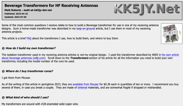 This FAQ covers building and buying transformers for loop-on-ground and Beverage antennas. Building one uses ferrite cores and thin wire. Buying is an option, with the DX Engineering BFS-1 being recommended. These transformers isolate the antenna from the cable to prevent unwanted signal pickup.