Search results
Query: design a j ple antenna
Links: 216 | Categories: 2
-
 This is a QST Article published in January 1982 by W1FB D. Demaw and HH Beverage and is a complete review of the original article published in 1922, which updates and reivew the beverage antenna theory and developlment, explaining the antenna design of transformers and gives accurate reports on antenna general performance.
 -
 A presentation of the Yagi Antennas, and other interesting tid-bits by Brian Mileshosky. The document provides an in-depth exploration of the Yagi-Uda antenna, detailing its historical development, design principles, and performance characteristics. Originally described in the 1920s, the Yagi antenna features a driven element and parasitic elements, including reflectors and directors, which collectively determine its behavior. The document highlights how element lengths, diameters, and spacing influence gain, impedance, and directivity. It also discusses the antenna's reciprocal nature and presents data on typical gain values for various element configurations. Additionally, the text covers practical considerations, such as the construction of a "Tape Measure Yagi" for amateur use, and touches on related antenna types like dipoles and their application in Near Vertical Incident Skywave (NVIS) communication.
 -
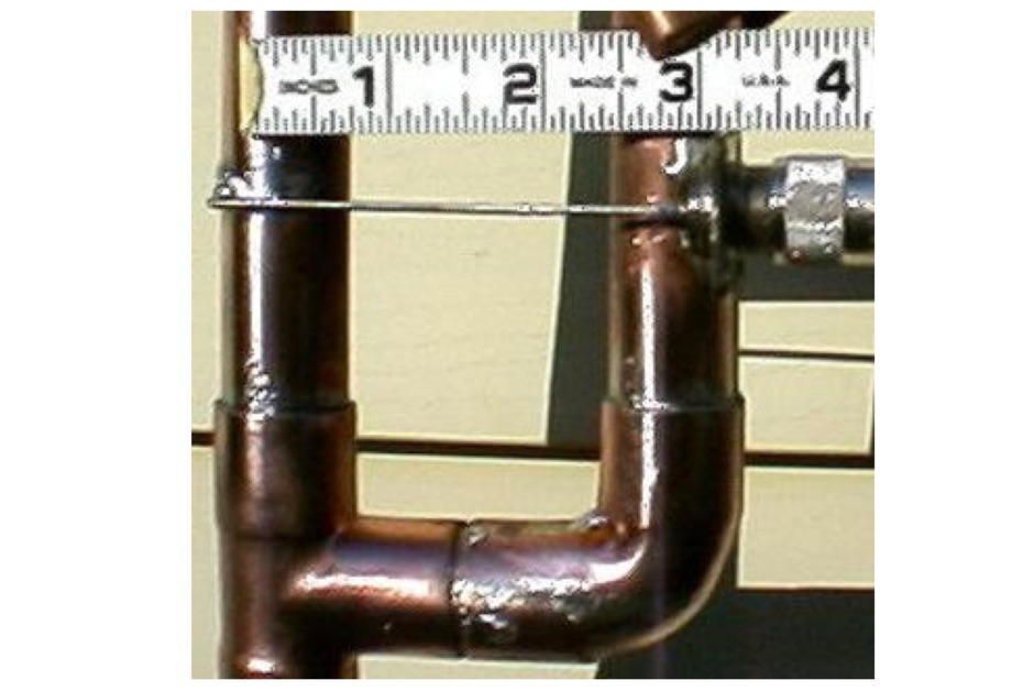 A copper J Antenna for 144 and 430 article with design, feeding methods and pictures
 -
 The Superantennas MP-1 portable HF antenna is analyzed for its design and field performance, particularly its high-Q loading coil and 3/8-inch mounting. The review details the antenna's construction, including an 8-inch vertical section, a large-diameter loading coil tuned by a sleeve, and a 4-foot whip that disassembles into six rods for transport. Initial testing with the supplied 10-foot ribbon cable "ground plane" yielded poor SWR and RF hot conditions, indicating an inadequate ground system. Further experimentation with longer radials and resonant counterpoises for each band improved matching and eliminated RF hot issues, but introduced significant operational complexity. The author notes the difficulty in optimizing both counterpoise length and coil setting without an antenna analyzer, and the sensitivity of the MP-1 to counterpoise deployment. The review also discusses the recommendation to tune for maximum received signals rather than minimum SWR, often necessitating an external ATU due to the antenna's typical low impedance. The **MP-1**'s critical dependence on resonant counterpoises for effective operation, especially when elevated, is highlighted as a major drawback for portable use. The author ultimately sold the antenna, concluding that despite its sound technical design, its fussy nature and the need for extensive counterpoise management or an ATU detract from its portability and convenience compared to simpler, less expensive dipole solutions. The **Superantennas MP-1** is deemed a flawed portable antenna, requiring considerable effort to achieve its claimed performance.
 -
 T2FD is a 600-900 ohms folded dipole, terminated with resistor. Feed impedance is coupled with 50/600 ohms voltage balun. It is a wide band antenna with rather low SWR over the full designed frequency range: antenna tuner is seldom needed.
 -
 Moxon is a rectangle shaped directional antenna, originally designed by Les Moxon G6XN. There are couple of advantages of using this antenna. It is small in size, Easy to mast, Balanced to 50 Ohms, Near 1:1 SWR, Excellent Front to Back (F/B) ratio, Large bandwidth
 -
 A simple, cheap and easy to build 26 feet long vertical antenna that works DX on 20 - 10 meters including WARC Bands, it is designed for portability for field days, camping, or permanent installation, cost, and to achieve at least 1/2 wavelength on the WARC bands.
 -
 This 6 meter 2 element yagi antenna is simple, compact and effective antenna for 50 Mhz. The design antenna was optimized with AO for best match to 50 ohms, no matching network. A choke balun is recommended to decouple feedline currents.
 -
 A 102-inch vertical whip, commonly a CB antenna, forms the core of this low-profile 10-meter antenna design, optimized for the 28 MHz band. The construction details specify three 8-foot radials made from scrap wire, connected to a common point. This simple yet effective setup is designed for ease of construction and deployment, making it accessible for operators with limited space or materials. The design emphasizes using readily available components, including PVC pipe for the mast and a SO-239 connector for the feedline, ensuring a straightforward build process for a resonant quarter-wave vertical. Field results indicate that this antenna provides good performance for local and DX contacts on 10 meters, despite its compact footprint. The author, N8WRL, shares practical insights into its construction and tuning, highlighting its suitability for temporary or permanent installations where a full-sized antenna might be impractical. Comparisons to more complex designs suggest that this low-profile vertical offers a respectable signal-to-noise ratio and effective radiated power for its size, proving that simple designs can yield satisfying on-air results.
 -
 An interesting presetnation full of usefull tricks to correctly design and build 23 cm Yagi using simple tools. The basic design of the antenna presented in this document is taken from the original DL6WU Yagi Design published in 1982
 -
 Complete collection of the four main parts of this excellet research on modelling and designing half wave dipole antennas for 40 meters band, covering all aspects beginning from full wave length antennas, to shortened, loaded and reshaped dipoles
 -
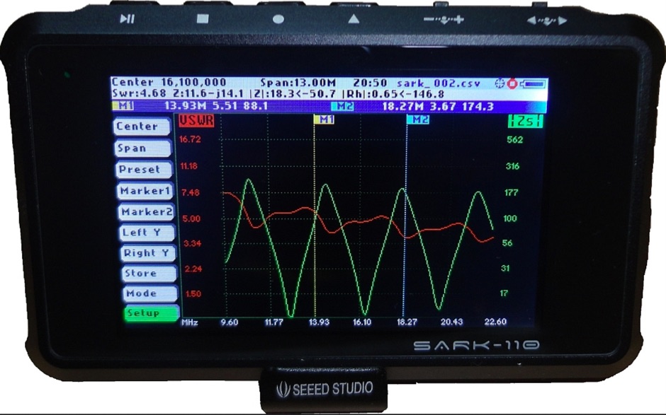 The SARK-110 is a completely new design concept for an Antenna Analyzer. This is a truly pocket size device, so you can take it anywhere. It offers a gorgeous 3" high-resolution, active-matrix color display that allows information-rich diagrams, works from 0.1 to 230MHz
 -
 Examines Radio Frequency Systems (RFS), a manufacturer specializing in high-performance cable solutions for diverse communication infrastructures. The company, with over 120 years of heritage, focuses on designing and producing robust, long-life connectivity systems, including _low loss foam dielectric RF cable_ and _premium radiating cable_. RFS's product range supports critical applications in cellular networks, microwave antenna systems, and specialized installations within buildings and tunnels. The resource highlights RFS's commitment to innovation, addressing emerging industry standards like _FRMCS_ for railway communication and advanced fiber solutions for data centers. It also details the company's manufacturing capabilities in Hannover, Germany, emphasizing the quality and reliability associated with _Made in Germany_ products. The content covers various connectivity landscapes, from urban solutions for connected cities to private 5G credentials and future plans. Specific product categories include _fiber, power & hybrid cable_, and _low loss high power air dielectric RF cable_, showcasing their broad portfolio for complex RF environments.
 -
 When assembling a robust shack, the quality of interconnects often determines overall system integrity and signal fidelity. Neutrik, with over 50 years in the connectivity sector, specializes in professional-grade connectors that withstand rigorous use in entertainment and industrial applications. Their product range includes XLR, speakON, powerCON, and opticalCON series, which are frequently adapted by hams for critical station infrastructure, particularly in contesting or DXpedition environments where reliability is paramount. Amateur radio operators often repurpose these durable connectors for antenna switching matrices, audio interfaces for digital modes, or power distribution systems. The robust locking mechanisms and high-quality contact materials found in Neutrik products ensure stable connections, minimizing intermittent faults that can plague field operations or even fixed station setups. This attention to mechanical and electrical integrity aligns well with the demands of high-power RF environments and sensitive receive chains. While primarily serving the pro-audio and video markets, the engineering principles behind Neutrik's designs translate directly to the needs of radio amateurs seeking superior performance and longevity from their cabling and connection points. Their commitment to innovation, as highlighted by their 50-year journey, suggests a continuous evolution of products that could benefit future amateur radio applications.
 -
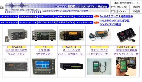 EDC is an amateur radio dealer for Heil Sound, Elecraft, Vibroplex and Force 12 antennas in Japan
 -
 Comprod Communications specializes in the design and manufacturing of RF communication solutions, including a comprehensive range of antennas, duplexers, multicouplers, and combiners. The resource details their product categories, which encompass base station antennas, mobile antennas, transit antennas, and disguised antennas, alongside mounting solutions and in-building systems. It highlights the company's 40-year history in adapting offerings to client needs and anticipating industry trends, emphasizing product durability and low maintenance for harsh environments. The company's offerings are presented as high-quality, designed to withstand extreme conditions from Arctic cold to equatorial heat and humidity. The site mentions solutions and technical sales support, training, and site analysis and system design as part of their service portfolio. It also references being a market leader trusted by over 1,000 customers worldwide, positioning itself as a partner for RF communication needs.
 -
 Cmpter Electronics specializes in the design and manufacturing of RF coaxial connectors, RF adapters, and RF cable assemblies, serving diverse applications across datacom/telecom, automotive, instrumentation, aerospace, and defense sectors. Their product line includes RF coaxial terminations, attenuators, and waveguide to coax adapters, catering to specific needs in radio frequency systems. The company also offers precision adapters and connectors, alongside glass beads and test cable assemblies, indicating a focus on high-quality components for demanding RF environments. Their resource center provides valuable information, including an "RF Made Simple" section and a product catalog for download, which assists engineers and technicians in selecting appropriate components. The product named system helps in identifying specific parts, streamlining the procurement process for complex RF solutions. With a comprehensive range of RF coaxial cables and related tools, Cmpter Electronics positions itself as a key supplier for critical infrastructure requiring reliable signal integrity. Their offerings support a broad spectrum of RF applications, from basic connectivity to advanced test setups.
 -
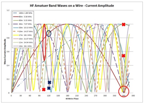
 Designing and constructing a two-element receiving loop antenna array for HF operation involves specific considerations for achieving high directivity and noise reduction. This resource details a homebrew system comprising two 30-inch diamond-shaped loops, spaced 20 feet apart, which are fed through mast-mounted preamplifiers and passive signal combiners. The operational principle relies on adjusting phase delays between elements via precise _Belden 8241_ coaxial cable lengths, optimized for specific bands from 160m to 20m. Performance data, derived from _EZ-NEC_ modeling, illustrates consistent 90° azimuth-plane beamwidth and low take-off angles across the target bands, with _Receiving Directivity Factor_ (RDF) values comparable to a 300-foot Beverage antenna. The article presents detailed elevation and azimuth plots for 20m, 30m, 40m, 80m, and 160m, demonstrating the array's ability to provide strong response at low DX angles while also supporting _NVIS_ signals. Key components like the _DX Engineering RPA-1_ preamplifier and _DXE RSC-2_ signal combiner are discussed, alongside the importance of impedance matching to preserve antenna patterns. The construction emphasizes self-contained elements that do not require ground radials, offering a compact solution suitable for suburban environments and stealth installations, with a focus on optimizing receive performance independently from transmit antennas.
 -
 Operating a modern amateur radio station, particularly for advanced digital modes or microwave experiments, often requires precise test and measurement equipment. This resource from NI (National Instruments), now part of Emerson, showcases a wide array of hardware and software solutions designed for demanding test objectives. Their portfolio includes modular instruments and configurable software interfaces, such as _LabVIEW_ and _TestStand_, which integrate AI assistance via _NI Nigel™ AI_ for code completion and sequence building. For those involved in RF and microwave work, the offerings extend to vector signal transceivers, RF signal generators, software-defined radios, and spectrum analyzers. These tools are crucial for characterizing antenna performance, optimizing transceiver circuits, or developing custom radio systems. The company emphasizes its 50 years of innovation, with 40 years dedicated to _LabVIEW_, highlighting a long-standing commitment to engineering solutions. The site also details products for data acquisition, electronic test, and wireless design, covering components like CompactDAQ modules for precise sensor measurements and various communication bus interfaces. Their events and perspectives sections offer insights into topics such as 5G technology and strategies for breaking out of testing silos, providing a broader context for their measurement solutions.
 -
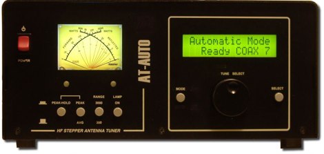 _AT Auto_ is an automatic antenna tuner designed for amateur radio enthusiasts seeking efficient and reliable tuning solutions. This device automates the tuning process, allowing operators to focus on communication rather than manual adjustments. The tuner is compatible with a range of transceivers, enhancing its versatility in different shack setups. Its design incorporates advanced circuitry to ensure optimal performance across various bands. The _AT Auto_ tuner is particularly useful for those operating in HF bands, providing seamless transitions between frequencies. Its integration capabilities with other shack automation products make it a valuable component for modern amateur radio stations. The tuner supports multiple modes, including _SSB_ and _CW_, catering to diverse operating preferences. Its robust construction and user-friendly interface contribute to its appeal among both seasoned operators and those new to the hobby. Kessler Engineering's focus on innovation and quality is evident in the _AT Auto_'s design. The tuner is part of a broader product line that includes shack automation solutions, reflecting the company's commitment to enhancing amateur radio operations. Despite the website redesign, the tuner remains a key offering in their product portfolio.
 -
 The OCFD Off-Center-Fed Dipole Antenna is an excellent multiband antenna that is relatively simple to construct, yet gets quite decent performance.
 -
 Constructing an End-Fed Half-Wave (EFHW) antenna offers a practical solution for HF operators seeking a multiband wire antenna without the need for extensive radial systems. This design typically employs a high-impedance transformer at the feed point, matching the antenna's inherent high impedance to a 50-ohm coaxial feedline. The article specifically details a 2012 approach, focusing on a transformer with a 49:1 turns ratio, which is a common configuration for EFHW antennas. The resource outlines the construction of a wire element cut for a half-wavelength on the lowest desired band, with specific coil arrangements enabling operation on harmonically related bands such as 40m, 20m, and 10m. It discusses the physical dimensions and winding details for the matching transformer, often utilizing a ferrite toroid core to achieve the necessary impedance transformation. The content provides insights into the operational principles and practical considerations for deploying such an antenna, including methods for tuning and optimizing performance across multiple amateur radio bands. While acknowledging that the presented information from 2012 may be superseded by newer insights, it serves as a foundational reference for understanding EFHW antenna theory and construction.
 -
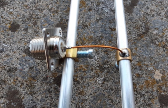
 The page provides information on a simple 50MHz J-Pole Antenna project based on the DK7ZB design. It explains the principle of the Wireman-J-Pole, the feeding process, practical mounting, and simulation results using MMANA GAL. The content aims to guide amateur radio operators in building their own J-Pole antennas for the 6-meter band.
 -
 The Tri-pole antenna, a clever modification of a standard dipole, allows for dual-band operation by integrating a third element. This design effectively shortens the overall dipole length by 10 to 20 percent, simplifying antenna rotation and offering a compact footprint. KK4OBI's article delves into the operational principles, using a 6 and 10-meter Tri-pole as a primary example, and provides comprehensive instructions for constructing any Tri-pole antenna within the 6 to 15-meter range. Key to the Tri-pole's performance is its off-center feed, necessitating a common mode choke at the feed point for optimal tuning and reduced noise. The author outlines a methodical approach to determining element dimensions, starting with a vertical element frequency calculated as 0.47 times the sum of the desired upper and lower band frequencies. This calculation, along with K-values derived from trend lines, guides the initial lengths for the horizontal arms, demonstrating how a 10m-6m Tri-pole can achieve a total horizontal length 78% shorter than a conventional 10-meter dipole. Tuning and balancing are critical, with the article detailing adjustments to arm lengths and the vertical element to achieve balanced SWR values, as validated through 4NEC2 simulations. Radiation patterns are analyzed at various elevations, showing gains around 5.7 dBi and favorable take-off angles for DX contacts. Construction details specify aluminum tubing dimensions, U-bolts, and an SO-239 connector, emphasizing the importance of a ferrite-based choke for wideband operation.
 -
 Operating in a Single Operator Two Radios (SO2R) setup, especially with beverage antennas, often exposes the receiving radio's front-end to significant RF energy from the transmitting radio. This resource details a practical, homebrew receiver protection circuit designed to mitigate this risk. The core of the design involves a non-inductive 2W 22 Ohm carbon composition resistor in series with the RX antenna line, followed by two stacks of four fast-switching diodes (e.g., _1N914_) configured in opposite polarizations. This arrangement effectively clamps the incoming voltage to approximately 2.8 V peak-to-peak, safeguarding sensitive receiver input components. The series resistor plays a crucial role by absorbing excess power, preventing the diodes from exceeding their current ratings and potentially failing open, which would leave the receiver unprotected. The author, _N4KG_, measured up to 50 watts of coupled power between 80M slopers on the same tower, highlighting the necessity of such protection. The design is presented as a cost-effective solution to prevent damage to receiver input transformers, with the author noting successful protection of a receiver even after a resistor showed signs of overheating. This simple circuit can be integrated via a transverter plug, offering a robust defense against high RF input.
 -
 This article presents a comprehensive guide to constructing a multiband vertical wire antenna. The design features parallel wires for various bands, all connected to a single balun, ensuring ease of assembly and adjustment. Materials required include a fishing rod, PVC tubing, and inexpensive wire. The antenna is lightweight, cost-effective, and suitable for field use or as an additional home setup. Detailed instructions and diagrams are provided to facilitate successful construction and optimal performance across multiple frequencies.
 -
 Documents S21RC's construction of an impedance transformer harness for a VHF/UHF cross yagi, utilizing 20m of _RG179_ cable. Details the creation of a DIY RF sampler with a -50dB sampling output, primarily for measuring HF radio PA section output with a Spectrum Analyzer, also applicable for _Pure Signal_ transmission. Chronicles the deployment of a 200m long beverage antenna for the _S21DX IOTA_ operation in 2022, positioned 2m above ground. Discusses the construction of a 3-element short beam for 10m to replace a previous 2-element antenna, with assistance from S21DW. Provides guidance on operating cheap _PA-70_ and _PA-100_ type Chinese SSPAs using IRF530 MOSFETs, emphasizing the necessity of a final LPF. Outlines the design and construction of a fully isolated interface for radio-to-computer connections, supporting various digital modes with isolated ground, audio transformers for IN/OUT, optical isolation for CAT/CIV, and isolated PTT/COS lines. Includes a log of software updates, such as the _HMI/TFT for NX8048K070_ and _2.1.14 Lite_ release with bug fixes for PEP hold and gradual watt decay.
 -
 The ARRL's End-Fed Half-Wave (EFHW) Antenna Kit is an easy-to-build four-band antenna designed for 10, 15, 20, and 40 meters. Ideal for portable operations, it includes a 49:1 impedance transformer for compatibility with most transceivers. This project, detailed with step-by-step assembly instructions, involves creating a weatherproof enclosure and impedance matching network. The kit simplifies HF operations and supports multiple configurations, making it a versatile tool for amateur radio opertors.
 -
 This is a simple half wave antenna for 70 cm band, made using the jpole design.
 -
 I used a FT 240-43 for much more power, not needed but beter safe than sorry. 150 Watt continious, 300 Watt PEP SSB, 90 Watt Digimodes 10 Mhz, 18 Mhz, 24 Mhz Very easy to build design and a good antenna for people who don't have much space for big towers or long wires This design is from Hans - PE1RNU
 -
 Constructing a dual-band antenna for 40 and 20 meters often involves compromises in size or complexity. This resource presents a compact _open sleeve dipole_ design that addresses these challenges by using 450-ohm ladder line and folded elements to achieve a total length of approximately **17.17 meters**, significantly shorter than a full-size 40-meter dipole. The design leverages electromagnetic coupling, where a primary radiator handles the 40-meter band, and a second conductor resonates on 20 meters without direct electrical connection. This configuration eliminates the need for traditional traps, loading coils, or switching components, simplifying construction and reducing potential loss points. The antenna is fed with RG-58C/U coaxial cable, and a common-mode choke is recommended at the feed point to suppress sheath currents, ensuring a cleaner radiation pattern and minimizing RF in the shack. The design is well-suited for portable operations, field deployments, temporary installations, and restricted urban environments where space is a premium, offering solid performance on both HF bands.
 -
 The "DIY Telescopic-V Antenna £35" project showcases the creation of a budget-friendly, portable telescopic V-shaped antenna inspired by commercial designs. Using eBay-sourced telescopic whips and custom mounting solutions, the author documents their process, testing, and adaptations. Despite challenges like weather and missing tools, the antenna performed well across multiple bands, enabling successful QSOs. Future improvements include exploring loading coils and testing in better locations. The compact design offers versatility for amateur radio enthusiasts seeking an affordable and practical solution.
 -
 Mitigating impulse-type noise, a common challenge in the **HF radio spectrum**, often requires specialized processing before the signal reaches the transceiver's receiver stages. The NR-1 addresses this by functioning as an RF interference removal device, specifically a noise blanker, targeting transient noise sources. Its operational range extends from 1.6 MHz to beyond 70 MHz, making it suitable for various amateur radio bands and general shortwave listening applications. Unlike QRM eliminators or X-phasers, the NR-1 does not require a separate noise antenna for its operation, simplifying its integration into existing station setups. The device's design focuses on wideband performance, allowing its use both within and outside the allocated amateur radio frequencies. Documentation detailing its operation is available, providing insights into its technical specifications and deployment. This unit is a hardware product, conceptualized and implemented by SV3ORA.
 -
 Microwaves101 provides an extensive repository of information covering fundamental principles of microwave design, targeting engineers and radio amateurs interested in the higher frequency spectrum. The site features a detailed _encyclopedia_ of microwave terms and concepts, alongside practical design considerations for various components and systems. It serves as a foundational reference for understanding RF propagation, transmission lines, and active/passive microwave circuits. The resource includes numerous calculators for impedance matching, filter design, and other critical RF parameters, facilitating hands-on project development. Discussions on **10 GHz** equipment and **24 GHz** projects highlight practical amateur radio applications, extending to operations up to 134 GHz. Content spans from basic theory to advanced topics like MMIC design and antenna characteristics, supporting both educational and practical endeavors in microwave technology.
 -
 F5NPV introduces a variant of the W8JK antenna design, employing the MOXON principle. With extended monopoles, it outperforms the Open-Folded W8JK, yielding a 1dbd gain improvement, enhanced performance on 30m and 10m bands, bi-directionality, and lower side attenuation. The design's focus on higher radiation impedance results in increased antenna efficiency and reduced losses. Despite these improvements, the bill of materials remains unchanged.
 -
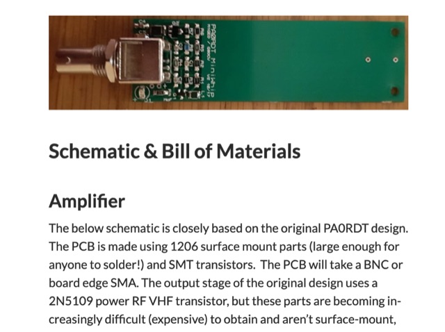 When experimenting with the WellGood Loop antenna, I came across the PA0RDT MiniWhip design referenced in several places. The construction of the PA0RDT MiniWhip is simpler than the WellGood Loop since there are no inductors to wind, but during my testing, I have found the loop to have slightly better performance.
 -
 This Field Day Vertical Antenna project is the result of many years of attending various field day sites and realizing that what was needed is a simple, easy to assemble vertical antenna. The design of this Field Day Antenna is not very novel and leverages ideas from Butternut verticals and ARRL publications. The one essential requirement was that the antenna can be raised by just one person. The design of this Field Day Antenna is an above ground mounted ground plane vertical.
 -
 Operating in antenna-restricted communities presents unique challenges for amateur radio operators, often necessitating creative solutions for antenna deployment. This resource details the design and implementation of stealth antennas within a townhouse community in Exton, PA, where external antennas were strictly forbidden by covenants. The author, WB5NHL, describes his setup, which involved locating the shack in the basement and utilizing an unused space under the roofline of a finished third-floor loft for antenna placement. The content specifically addresses the practicalities of routing coax cables three floors and maximizing antenna performance within limited attic space. It covers solutions for multi-band operation, including dedicated sections for 40-10 meter and 80-meter antennas, along with strategies for mitigating potential interference issues. The approach emphasizes full compliance with community covenants, achieving maximum height-above-ground for horizontal antennas, enabling instant band switching, and efficiently utilizing available attic volume. While acknowledging limitations such as potential interference with high power and fixed antenna patterns, the resource provides a detailed account of a functional compromise for restricted environments. Links to individual pages on _coax cables_, _40-10 meter antennas_, _80-meter antennas_, and _interference issues_ offer deeper dives into each specific aspect of the installation.
 -
 The PAC-12 Antenna, a multi-band portable vertical, is meticulously detailed in this construction article by James Bennett, _KA5DVS_. The design emphasizes ease of homebrewing using readily available components from local hardware stores, including replaceable loading coils. It outlines the preparation of the 72-inch telescoping whip (originally from Radio Shack, with an alternate source now provided by _Pacific Antenna_), the construction of the loading coils from PVC risers, and the fabrication of the aluminum rod base sections. Specific instructions cover threading aluminum rod with a _1/4-20 threading die_ and assembling the feedpoint insulator with a BNC connector, along with recommendations for radial deployment. KA5DVS, an avid traveler and QRP enthusiast, developed the PAC-12 to address the bulkiness of random wire setups and the limitations of commercial portable antennas like the Outbacker or SuperAntennas MP1. His goal was a lightweight, packable antenna that disassembles into 12-inch sections, achieving an assembled length of approximately 8 feet. The design strategically places the loading coil away from the base for improved efficiency. The PAC-12 notably placed first in efficiency compared to a quarter-wavelength wire vertical at the HFPack antenna shootout during the Pacificon conference in October 2001, demonstrating its practical performance for field operations. Appendix C showcases various _NJQRP Club_ members' PAC-12 constructions, including a 20m beam made with multiple PAC-12 elements.
 -
 This article describes a simple yet effective multi-band vertical HF antenna design that performs exceptionally well across 80m to 10m bands. The antenna consists of a 13.4m wire mounted on a 12.4m Spiderpole, complemented by four 12m radials and a ground rod. Initially tuned with a manual LC circuit, it was later upgraded with a CG3000 remote auto ATU for convenient band switching. Despite antenna modeling software suggesting limited performance on higher frequencies, the system demonstrated excellent DX capabilities across all bands, outperforming more complex vertical antenna designs.
 -
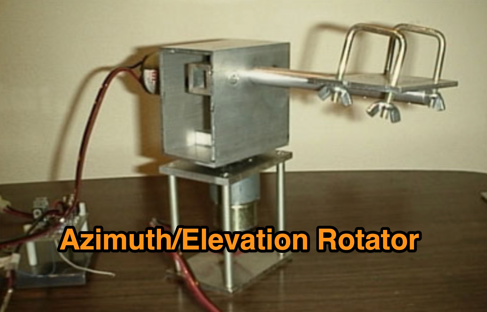 Learn how to build a simple 12vdc azimuth and elevation motor unit for the Arrow Satellite Antenna to improve your FM satellite communication experience. This DIY project involves using a camera tripod and basic materials like aluminum tube and standoffs. Get detailed instructions, including the gearhead motor product number for optimal performance. Discover where to purchase the necessary components and stay updated on alternative motor options. Enhance your ham radio operations with this homemade rotator setup, designed for easy satellite tracking and communication. Share feedback and connect with other radio enthusiasts for more tips and ideas.
 -
 Operating within the low-frequency spectrum, transformers serve critical roles in antenna systems, particularly for 160m applications. The resource details the construction and performance of 1:1 transformers built on BN-73-202 cores, emphasizing their use as hybrid combiners or phase inverters for RX antenna arrays. Measurements reveal that these transformers exhibit minimal losses, around 0.12 dB at 1.8 MHz, with variations based on wire type and number of turns. The analysis includes comparative data on transformer performance, highlighting the impact of different winding techniques on frequency response. Notably, the use of coaxial cable for winding improves bandwidth while maintaining low-frequency efficiency. The resource also discusses braid breaker transformers, which minimize inter-winding capacitance, achieving low losses around 0.21 dB at 1.8 MHz. These insights are crucial for optimizing low-band antenna systems, allowing operators to make informed decisions regarding transformer design and implementation.
 -
 Dipole for 40m band. It is a simple linear loaded dipole feeded with 450-Ohm openwire feedline. Designed it for resonance at 7.050 MHz, can be tuned on 30m and 80m bands with an external antenna tuner. Build with simple electrical copper wire (2.5 mmq/13 awg) and two fishing poles with size of about 7 m/23 ft.
 -
 Constructed in May 2008, this innovative 4m tall electrically full-size halfwave vertical dipole, tunable to multiple bands, offers HF coverage despite its space-saving design. Inspired by cost-effective DIY alternatives, the antenna design departs from conventional center-fed approaches, utilizing asymmetrical dimensions. Despite resonance challenges, the antenna's performance remains viable, boasting broad bandwidth and adaptability, as demonstrated through SWR measurements and EZNEC predictions.
 -
 Learn how to easily build a 10-meter vertical antenna, perfect for DX contacts on the amateur radio bands. This flowerpot or T2LT design is portable, efficient, and ideal for ham radio operators looking to improve their DX performance. With just a few basic tools and materials, you can construct this antenna for portable operations or as a home station setup. Discover how to set up the antenna, improve its performance by raising it higher, and start making contacts with stations around the world. Watch a step-by-step guide on YouTube for building and testing this DIY ham radio antenna.
 -
 Originally designed by John Kraus, W8JK in about 1940, this antenna has some interesting properties. The W8JK antenna is 2 (Two) centre-fed double-dipole fed by a pair of anti-phase signals. Small size, simple antenna, offer nice performance but need a tuner. Tested in this project from 30m to 6m bands
 -
 A simple superheterodyne receiver (3.5–30 MHz) for amateur radio achieves stable SSB-CW reception using modern BJTs, an AD831 mixer, a 6-pole quartz filter, and Seiler oscillators. Designed with high IF (4.5 MHz), compact AM-FM variable capacitors, and modular resonant circuits, it ensures selectivity, image rejection, and stable tuning. Built in a copper-lined wooden case, it features practical assembly techniques but lacks advanced features like AGC or S-meter. Effective on basic antennas, it achieves global reception.
 -
 A coaxial cable trap is a fundamental component in multiband antenna design, enabling a single radiator to resonate efficiently on multiple frequencies by electrically shortening or lengthening the antenna element. This project focuses on constructing such a trap for a vertical antenna operating on the 10 MHz (30m) and 14 MHz (20m) amateur bands, providing practical insights into its fabrication and integration. The article outlines the specific dimensions and winding techniques for the coaxial trap, emphasizing the use of readily available materials. It details the physical construction of the vertical element, including the mast and radiating sections, to achieve optimal performance across both target bands. The author shares personal experiences with similar trap designs, noting their effectiveness in previous horizontal dipole configurations. Key construction steps are illustrated with _original photos_, showing the assembly of the trap and its incorporation into the overall antenna structure. The design aims for a compact footprint, making it suitable for limited space installations while still delivering effective DX capabilities on the **30-meter** and **20-meter** bands.
 -
 In this article, Steve G0UIH presents a straightforward guide for constructing a lightweight 15m 3 Element Yagi antenna with impressive performance metrics. With a focus on ease of construction and efficiency, the design boasts a nearly 8.2dbi forward gain and 30db front to back ratio. Utilizing readily available materials and a hairpin match for impedance matching, this Yagi offers broad bandwidth and simple tuning for optimal operation across the 15m band.
 -
 This article describes the construction of a three-band vertical antenna for the WARC bands (10, 18, and 24.9 MHz). Unlike a previous design using thin wire requiring a complex matching device, this version uses a telescopic set of pipes, reducing reactances and simplifying the matching device to two coils and two capacitors. The article provides details on the antenna model, the matching device circuit, and tuning methods, including the use of frameless coils and variable capacitors. With proper tuning, the antenna achieves a VSWR not exceeding 1.3 across all bands, demonstrating a practical and efficient design for amateur radio enthusiasts.