Search results
Query: vhf antenna
Links: 331 | Categories: 13
Categories
- Shopping and Services > Antennas > VHF Antenna
- Manufacturers > Antennas > VHF UHF Microwave > Discone Antennas
- Manufacturers > Antennas > VHF UHF Microwave > Mobile Antennas
- Manufacturers > Antennas > VHF UHF Microwave > Quad Antennas
- Manufacturers > Antennas > VHF UHF Microwave > Vertical Antennas
- Antennas > VHF UHF
- Manufacturers > Antennas > VHF UHF Microwave > Yagi Antennas
- Manufacturers > Antennas > VHF UHF Microwave
- Manufacturers > Antennas > Broadcast
- Antennas > Collinear
- Antennas > Handhelds
- Shopping and Services > Marine Radio
- Antennas > Mobile
-

-
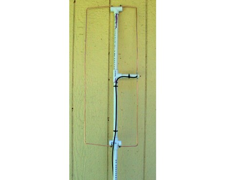 Presents the construction and performance characteristics of a **2-meter vertical Moxon** antenna designed by WB5CXC. The antenna utilizes 1/2-inch PVC and #6 copper ground wire for its physical structure. Performance data includes measured front-to-back ratio using a local repeater, demonstrating significant signal attenuation when rotated. The resource provides **antenna pattern** plots, with blue tracing the design at 146 MHz and red indicating performance at 148 MHz. Gain and SWR plots are also included, alongside a detailed diagram of the antenna's physical layout. The design emphasizes a good front-to-back ratio, aligning with modeling predictions.
 -
 A _Topfkreis_ antenna, also known as a "bicycle pump" antenna, is presented as a simple vertical design for the 70 cm band. This variant of the J-pole antenna is notable for not requiring a ground plane, simplifying deployment. The construction details specify using aluminum tubing for the radiating element, with precise measurements for the quarter-wavelength outer tube (32 mm diameter) and the three-quarter wavelength inner sliding tubes (10 mm and 8 mm). Feeding is via a 50-ohm coaxial cable connected 90 mm from the base of the central tube. This design can achieve a gain of **4 to 6 dB** when properly tuned using the adjustable radiating element. The article details the fabrication of a critical aluminum washer, suggesting a method using a hole saw and a drill press as a lathe for precise adjustment. The illustrated example is specifically for the 70-centimeter band, and the author, Pop, clarifies construction points in the comments, including material choices and assembly techniques, ensuring a robust build for VHF/UHF operation.
 -
 TRasceivers HF-VHF-UHF, repeaters, GPS, antennas, based in italy
 -
 Cheap and EZ to build Bi-Directional VHF & HF antennas with gain
 -
 Dutch Antenna and Tower Manufacturers from Slimline Square Triangular Round Towers. Antennas production include Yagi Monoband/Dipole/HF Quad /50MHz and 70MHz Yagi-Quad, VHF-UHF yagi-Quad and Comby antennas VHF/UHF/SHF
 -
 The PDF document, titled "J-Poles," presents various J-pole antenna designs covering the 50 MHz to 450 MHz frequency range. It includes construction details for several specific bands, such as a 6-meter J-pole, a 2-meter J-pole, and a 70-centimeter J-pole. The content outlines the fundamental principles of J-pole operation, including the quarter-wave radiator and half-wave matching stub. Each design features specific dimensions for elements like the radiator length, stub length, and spacing, often expressed in inches. The document also discusses feeding arrangements and impedance matching considerations inherent to J-pole antennas. It provides practical guidance for homebrewing these antennas using common materials like copper pipe or wire elements. The resource offers insights into the advantages of J-poles, such as their omnidirectional pattern and ease of construction, making it a practical reference for radio amateurs interested in VHF/UHF antenna projects.
 -
 Plans and drawings of common amateur radio antennas, like jpoles, copper cactus, super jpole, omnidirectionals and quads
 -
-
 VHF UHF Amateur radio antenna and antenna parts, accessories for homebrewers, antenna kits, tubes, antenna masts, antenna tripores, insulators, power amplifier mosfet, power splitters by I0JXX
 -
 The page discusses Axial-Mode Helical Antennas, focusing on turning helical antennas over perfect ground and modeling helices in NEC-2 for optimized design. It covers topics such as high-gain performance, broadband, impedance matching, radiation pattern, feedline, balun, near field, far field, and DIY applications.
 -
 VHF, UHF, CB antennas for marine, mobile, base, remote radio monitoring and control system
 -
 Helical antennas have long been popular in applications from VHF to microwaves requiring circular polarization, since they have the unique property of naturally providing circularly polarized radiation. Paul Wade W1GHZ
 -
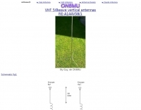 By Guy, de ON6MU, At VHF, both the 1/4-wavelength monopole and the 5/8-wavelength monopole antennas are widely used.
 -
 Hilberling GmbH based in Rendsburg Germany manufacturer of HF VHF Transceivers, rf power amplifiers, power combines, RF generators, power supplies, Antenna Diplexers and Triplexers
 -
-
 The resource details the construction of a 6-meter _Moxon_ antenna, presenting two distinct versions: one horizontally polarized for 50-51 MHz CW/SSB and another vertically polarized for 52-54 MHz FM. It specifies the use of 5/8 inch OD and 1/2 inch OD aluminum tubing, with 3/8 inch OD solid aluminum for corners, and provides a comprehensive material cutting schedule. The design aims for robust, portable construction, with all materials costing under $100. Detailed drawings and EZNEC models are referenced for precise dimensions and assembly, ensuring accurate element spacing and impedance matching. The EZNEC model for the H-POL version predicts a gain of **11 dBi** and a front-to-back ratio of **25 dB** at 50.5 MHz, while the V-POL version shows a gain of **6.7 dBi** and a front-to-back ratio of **36 dB** at 53 MHz. The article includes practical SWR measurement advice, noting the impact of coax length and loss on analyzer readings. Field tests during a tropical storm demonstrated the antenna's durability and performance, yielding numerous contacts across significant distances, including California, Colorado, and Texas, on SSB and PSK.
 -
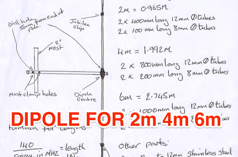 A dipole for 2m, 4m, 6m band an hamdwritten note for a homemade vhf antenna that can be tuned across the VHF band
 -
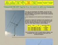 A triband VHF Yagi antenna for 6 m, 4 m and 2 m with one feed-point by DK7ZB
 -
 A 2m Moxon antenna project, designed for the 145 MHz amateur radio band, provides a compact, directional solution for VHF communications. This resource details the construction process, specifying materials like PVC pipe for the frame, copper wire for elements, and a SO-239 connector for the feedpoint. The design emphasizes ease of build for hams seeking a gain antenna with good front-to-back ratio for local ragchewing or contesting. The project outlines precise element lengths and spacing, crucial for achieving the desired impedance and radiation pattern. It includes a visual representation of the antenna's dimensions and assembly, allowing for straightforward replication. The Moxon's inherent characteristics offer a practical alternative to larger Yagi arrays, particularly for portable operations or restricted spaces, while still delivering effective directivity and gain.
 -
 German antenna manufacturer for VHF UHF antennas, Quad-antennas, yagi-Antenna, LPDA-Antenna, W-Lan Antennas.
 -
 The **2M Moxon antenna** design presented operates at 144 MHz, providing a compact, directional solution for VHF communications. Construction involves aluminum tubing for the elements, with specific dimensions for the driven element and reflector to achieve optimal performance. The design aims for a good front-to-back ratio and a relatively low SWR across the 2-meter band, making it suitable for portable or fixed station use where directivity is beneficial. Element lengths are critical for proper resonance and pattern. The driven element measures approximately 38.5 inches, while the reflector is slightly longer at 40.5 inches. Spacing between the elements is 12 inches, forming the characteristic Moxon rectangle. This configuration yields a gain of about 5.5 dBi and a front-to-back ratio exceeding 20 dB, which is advantageous for reducing interference from unwanted directions. Feedpoint impedance is close to 50 ohms, allowing direct connection to coaxial cable without complex matching networks. The antenna's lightweight structure, typically under 2 pounds, facilitates easy deployment and rotation, making it a practical choice for field operations or as a compact home station antenna.
 -
 Demonstrates the design principles and performance characteristics of **corner reflector antennas**, emphasizing their high gain and directional properties. It covers critical design factors such as the corner angle and the spacing between the radiating dipole and the reflector vertex. The resource explains how reducing the corner angle increases gain but lowers feed impedance, making matching more challenging. Practical angles of 90 degrees or 60 degrees are discussed, with 90 degrees offering easier impedance matching despite slightly lower gain. Details key design considerations, including reflector side length exceeding two wavelengths and reflector width greater than one wavelength for a half-wave radiator. It specifies reflector construction using wire netting, sheet metal, or parallel metal spines spaced less than 0.1 wavelength. The article provides a table with general dimensions for UHF and VHF bands, noting typical impedance values of 50 to 75 ohms and expected SWR of 1.7:1 on the lower band edge. Adjustable radiator-to-vertex spacing is highlighted as crucial for final tuning.
 -
 High End isopole VHF & UHF antennas for Amateur, Commercial and Military applications.
 -
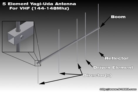 A project for a home made 5 element yagi-uda antenna for 2 meters, covering 144-148 MHz band by N1BMX
 -
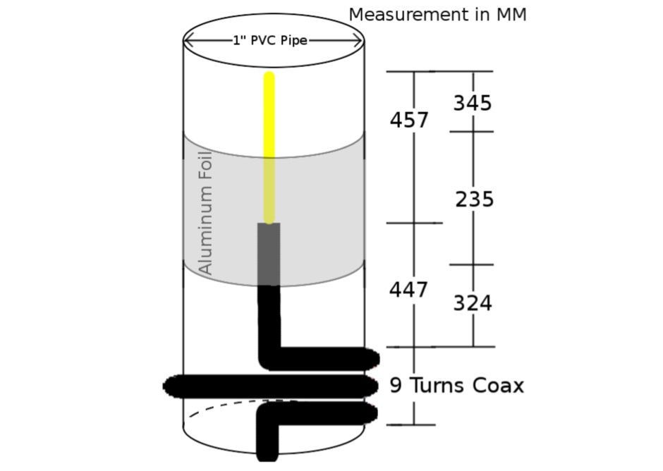 A homemade VHF/UHF vertical antenna made essentially with RG58 coax cable, with a 9 turns choke balun to prevent the shield acting as a RF Radiator.
 -
 You can make your own 2-meter "rubber duckies" that will likely perform much better than many commercial units.
 -
 Cheap UHF antenna plans for 2 meters and up including 421 1296 and 902 Mhz
 -
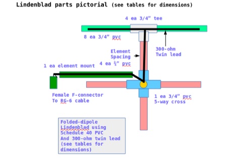 This document contains the detailed instructions to build a homemade lindenblad antenna using a twin-lead as dipole elements. This document contains 9 pages and includes a detailed construction sequence and some drawings to build this antenna for UHF and VHF ham radio bands
 -
 Offer a wide range of homebrewing projects mainly for VHF UHF operations. From vhf antennas to preamplifiers, chargers and power supplies
 -
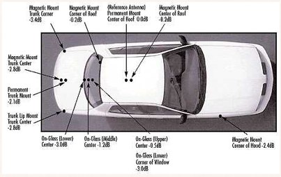 Mobile antenna placement presents unique challenges for the amateur radio operator, often requiring compromises between RF performance and mechanical considerations. This resource from KV5R.COM offers practical insights into achieving effective installations, drawing on real-world experience with different vehicle types. It details how factors like ground plane availability, proximity to vehicle structures, and antenna type (e.g., **HF mobile**, **VHF/UHF mobile**) influence signal radiation patterns and overall system efficiency. The author discusses common scenarios, from sedans and SUVs to trucks and RVs, highlighting the impact of mounting locations such as the trunk lip, fender, or roof. Specific attention is given to minimizing RF interference and maximizing radiated power, crucial for reliable mobile communications. Understanding the interaction between the antenna and the vehicle's metallic body is key to a successful mobile setup, and this content provides a solid foundation for making informed decisions.
 -
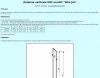 A vertical monoband antenna design that can work from 6 meters to 70 cm by F5ZV in French
 -

-
 The GW3YDX Super Moxon antenna design improves upon the standard Moxon Rectangle by incorporating additional directors in a rectangular configuration, yielding enhanced directivity and gain. For the 6m version, modeling with 4NEC2 and EZNEC+ indicated a 3dB gain increase and a 26.5dB front-to-back ratio, with VSWR below 1.5:1 between 50.0 and 50.3MHz when optimized for 50.1MHz. This design achieves a narrower -3dB power point beamwidth of 60° compared to the original Moxon's 80°, contributing to better QRM rejection. The boom length for the enhanced design is just under 2m, approximately double the original Moxon's, with no increase in wingspan. Construction details include tubing lengths for 6m, 4m, and 2m versions, with specific dimensions provided for elements A through M, measured to tubing centers. For instance, the 6m version uses a 2160mm element A and a 2140mm element H. The design maintains a 50-ohm feed impedance, with practical models showing VSWR plots consistent with simulations after minor adjustments to driven element lengths. The article also references Moxgen software for initial Moxon parameter calculation and NEC/EZNEC model generation. The 2m Super Moxon version measures approximately 30" x 25", demonstrating the compact nature of the design across different VHF bands. The article highlights the antenna's performance in real-world DX contacts on 6m, achieving contacts with over 80 stations in the USA from a modest QTH.
 -
-
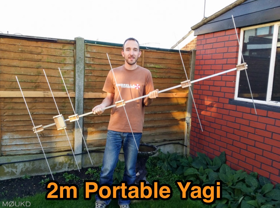 Building a 2 metre 144MHz VHF Yagi beam antenna, designed for portable use.
 -
 Located in southern Ontario Canada, supplier for HF VHF antenna kits, aluminium tubing, portable j-pole antennas, lightning suppressors, connectors and adapters
 -
 VHF UHF diplexer by G8MNY
 -
 An easy portable VHF antenna to build for ARES - RACES work is the 300 Ohm Twin Lead JPole antenna
 -
 Using our components you can build a rotating tower with greater capability than 3-4 static towers. A rotating tower allows common rotation of HF stacked arrays, VHF and UHF arrays, and antennas mounted at optimum heights. Component design also allows tower shunt loading and end support for wire antennas
 -
 RFAC Solutions specializes in providing a range of RF components, including various connector types, cable assemblies, attenuators, and filters. Their product line features common connector standards such as SMA, BNC, TNC, N-Type, MCX, and MMCX, essential for reliable RF signal paths in amateur radio and commercial applications. The company also offers high-power VHF amplifiers, catering to needs for signal boosting in specific frequency ranges. Their offerings extend to dust caps and adapters, which are crucial for maintaining the integrity and versatility of RF systems. The focus on supplying components from South Korea suggests a commitment to specific manufacturing standards and supply chain practices. This resource details a vendor's product scope, useful for hams sourcing specific parts for shack builds or antenna projects. Jeff is listed as a contact for inquiries.
 -
 A Unique VHF Antenna with gain over a J-Pole Jose I. Calderon, DU1ANV
 -
 Demonstrates the construction of a 144 MHz turnstile antenna, detailing its design for omnidirectional, horizontally polarized VHF operation. The resource outlines the physical dimensions and materials required, including specific lengths for the radiating elements and the use of _RG-58_ coaxial cable for phasing. It covers the assembly process, emphasizing the critical spacing and connection points to achieve the desired radiation pattern and impedance matching for the _2-meter band_. The article presents measured _SWR_ performance across the 144-146 MHz segment, showing a low SWR of 1.2:1 at 144.5 MHz, which is suitable for general VHF use. It compares the turnstile's performance to a 9-element Yagi, noting the turnstile's advantage in providing consistent signal strength from all directions without requiring a rotator. Practical application for local FM simplex and repeater operations is implied, offering a simple yet effective antenna solution for fixed or portable stations.
 -
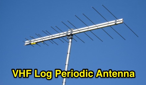 17-Element Very High Frequency/Ultra High Frequency Log Period Dipole Array
 -
 US Antenna manufacturer offering base and mobile antennas for 2 meter, 1.25 meter and 70 cm Amateur Radio GMRS and MURS Citizens Band Radio VHF and UHF Business Band Radio HF, VHF and UHF Scanning
 -
-
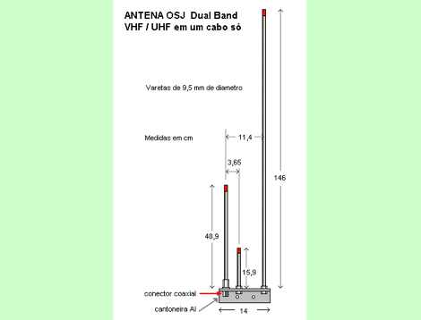
 The resource presents a detailed schematic for constructing a dual-band vertical antenna, specifically designed for operation on the 2-meter and 70-centimeter amateur radio bands. It illustrates the physical layout, critical dimensions, and component placement necessary for successful replication. Key elements such as the radiating elements, phasing sections, and feed point are clearly depicted, providing a visual guide for radio amateurs undertaking a homebrew antenna project. The diagram specifies the lengths for the VHF and UHF sections, indicating how these elements are integrated to achieve dual-band functionality from a single coaxial feedline. It also implies the use of common materials readily available to most experimenters, focusing on simplicity and effectiveness in its design. The visual format of a GIF image ensures direct access to the construction details without requiring extensive textual interpretation. This schematic serves as a practical reference for hams interested in building a compact, efficient vertical antenna for local and regional FM communications, offering a proven design for immediate implementation.
 -
 A 2-meter Moxon beam antenna, designed for the _144 MHz_ band, is detailed, originating from a desire to participate in the PW 2m QRP contest. The design, based on a Moxon Rectangle, offers a compact directional solution for VHF portable operations. The author, G0KYA, constructed the antenna using readily available materials like 15mm plastic conduit for the frame and 1.5mm copper wire for the elements. Initial testing with an MFJ-259B antenna analyzer showed a **1.2:1 SWR** at 144.300 MHz, indicating good resonance. The antenna's compact size, approximately 70cm x 40cm, makes it highly suitable for portable QRP work, providing a significant advantage over an omnidirectional vertical. The project includes practical advice on element spacing and construction techniques, emphasizing ease of assembly for field deployment. Field results from a local hilltop demonstrated the Moxon's directional characteristics, allowing for effective nulling of local noise and improved signal reception from specific directions.
 -
 Spanish radio dealer offer accessories, antennas and battery chargers, mounting accessories, cables and connectors, radio kits, power supply, pmr, vhf/uhf radios, all products for CB, ham radio and SWL.
 -
 This antenna is designed to be mounted off the side of a tower. Works on 136-153 Mhz range but also on 70 cm band