Search results
Query: do antenna
Links: 699 | Categories: 7
-
 Double Bazooka Antenna, a simple coax based and broad band antenna you can easily build
 -
 A helpful guide to building your own beverage-type low noise receiving antenna for broadband use. Easy, do-it-yourself suggestions to optimize directional performance, even if you lack a farm to put it on.
 -
 Ham radio antennas and electronics, specialized in 1/2 wave dipole, OCF dipole, windom, full wave loop, end fed, inverted L, portable end fed antenna, long wire, SWL antenna, fan dipole, multiband dipole, G5RV and military antennas.
 -
 Some antenna manufacturers place baluns at the incorrect location in LPDA arrays. If we consider what the balun does we can see how the mistake occurs.
 -
 This document details the design and construction of a Vinecom 6N4 dual-band Yagi antenna for the 50MHz (6-meter) and 70MHz (4-meter) amateur radio bands. The antenna features 9 total elements (4 elements for 50MHz, 5 elements for 70MHz) on a 4.236-meter aluminum boom. Computer simulations using MMANA software predict 7.21 dBd gain on both bands with front-to-back ratios of 16.01dB (6m) and 15.37dB (4m). The design uses 12.7mm diameter elements mounted on a 32mm square boom, weighing 5.7kg total. Practical measurements with an MFJ-269 analyzer confirmed good SWR performance across both bands after element length adjustments.
 -
 The document provides a comprehensive overview of baluns, which are devices used to connect balanced loads, like dipole antennas, to unbalanced inputs, such as coaxial cables. It covers various types of baluns, including voltage and current baluns, and their design, construction, and testing. The text discusses the importance of baluns in preventing RF currents on coax shields and their applications in Ham radio setups. It also includes practical advice on selecting and using baluns based on antenna impedance and power ratings, along with detailed performance evaluations and construction tips for different balun configurations.
 -
 A shortened 160 meters band antenna for hams who do not have 260 ft of space, based on a open-wire-fed short dipoole
 -
 A short dipole wire antenna for 40 meters band. It is a folded dipole that do not make use of coils and can be used either in horizontal or inverted V configuration
 -
 An attic antenna for 40 and 80 meters band by NS1W
 -
 The G5RV multiband HF antenna, designed by Louis Varney (G5RV) in 1946, is a popular compromise antenna offering good overall performance on most HF bands when paired with an external antenna tuner. The basic full-size G5RV measures 102 feet across the top for 80 through 10 meter operation and is fed at the center via a 34-foot low-loss feed-stub. This interaction between the radiating section and the feed-stub facilitates matching across 80-10 meters with a standard tuner, often eliminating the need for ladder line directly to the shack. The antenna's design center frequency is 14.150 MHz, configured as a 3/2-wave dipole on 20 meters, with its 102-foot length derived from long-wire antenna formulas. Construction details emphasize the matching section, which can be open wire, ladder line (window-type), or TV twin lead. Each type has a specific velocity factor (VF) affecting its physical length for an electrical half-wave on 14 MHz; for instance, open wire requires 33.7 feet (VF 0.97), ladder line 31.3 feet (VF 0.90), and TV twin lead 28.5 feet (VF 0.82). The article provides formulas for calculating these lengths and discusses the antenna's behavior on individual bands, from 3.5 MHz where it acts as a shortened dipole, to 28 MHz where it functions as two three-half-wave long-wire antennas fed in-phase. Practical construction notes include recommendations for vertical descent of the matching section, sealing the coax junction, providing strain relief, and winding a coaxial choke coil to mitigate common mode current. The resource also presents dimensions for double-size (204 ft) and half-size (51 ft) G5RV versions, along with their corresponding matching section lengths for various line types, making it a versatile reference for hams considering this classic wire antenna.
 -
 This article describes the antenna for Low Frequency Beacon. It originally appeared in the "Lowdown" for Oct. 1999.
 -
 A well documented article about construction and analysis of a horizontally polarized halo antenna for 6 meters band by Dr. Carol F. Milazzo, KP4MD
 -
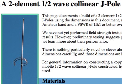 This article document a 2 element half wave collinear J-Pole antenna by KC9EOT and KB8OJH
 -
 Article on a 2 and 6 meters halo antennas that does not require a mast has a very low part count and can easily be built with a minimum of tools.
 -
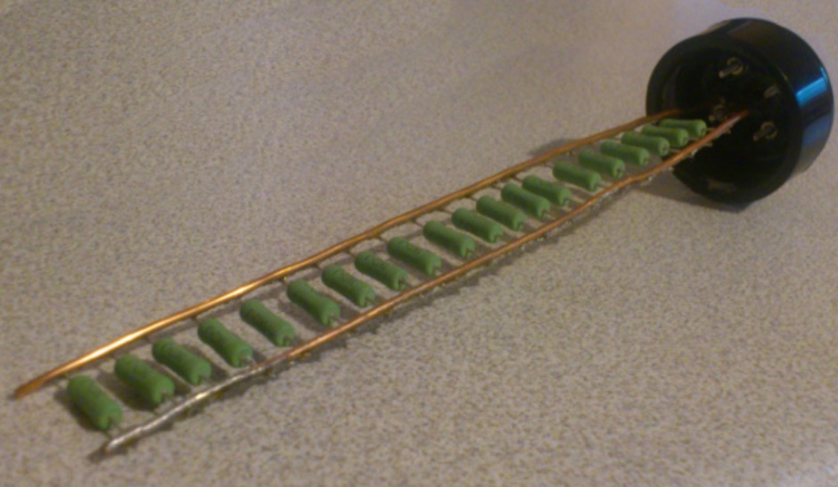 If your doing any home brewing gear for ham radio its a great idea to have a dummy load. This will to your radio be the perfect antenna...it will never radiate but your radio sees a perfect 50 Ohm impedance.
 -
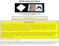 A Low -Power Indoor Portable HF Antenna by Monty Northrup, by N5ESE
 -
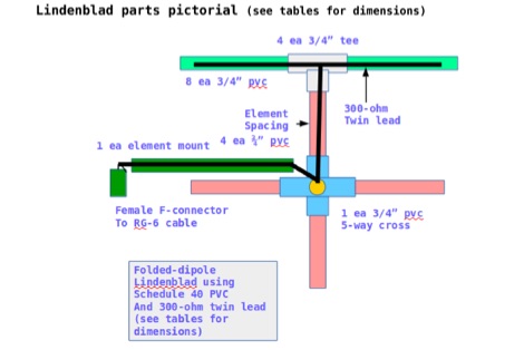 This document contains the detailed instructions to build a homemade lindenblad antenna using a twin-lead as dipole elements. This document contains 9 pages and includes a detailed construction sequence and some drawings to build this antenna for UHF and VHF ham radio bands
 -
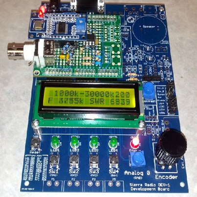 This article explain how to homebrew and use an HF antenna analyzer by simply adapting a Windows PC, micro-controller and a DDS evaluation board by K6BEZ
 -
 Manufacturer of single band and multiband transceiver bandpass filters for HF. High pass filters, two radoi headphones mix and switch, 6 meter portable antenna, antenna remote switching and steering.
 -
-
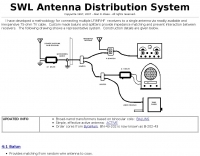 a methodology for connecting multiple LF/MF/HF receivers to a single antenna via readily available and inexpensive 75-ohm TV cable.
 -
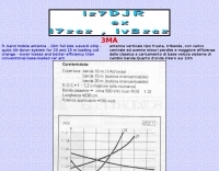 3 band mobile antenna - 10m full size wave/4 whip - quick tilt-down system for 20 and 15 m loading coil change by IZ7DJR
 -
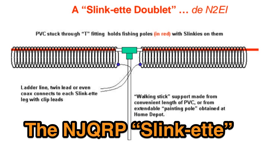 A Slinky-based doublet or loaded vertical QRP antenna tested for 40 meters band
 -
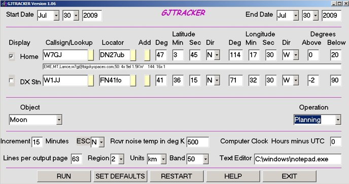 GJTracker is a antenna tracking program for windows written to be compatible with WSJT
 -
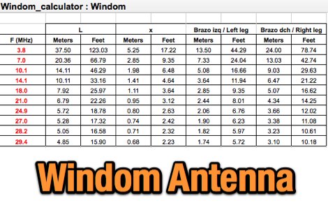 This article describes the characteristics of the Windom antenna and shows the results of several simulations made with MMANA-GAL, covering models optimized for the 20 m, 40 m and 80 m bands.
 -
 2 Meter Indoor Slim Jim Antennas for Cyclone Season and Other Uses by VK4MDX
 -
 A radio's transmitting power can be concentrated along the horizon by use of a GAIN antenna. Although you may still be transmitting with four watts of power, your effective radiated powerwill be greatly increased. This table shows the effects of antenna gain on a transmitter with 4 watts of transmit power.
 -
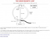 This ia a home built Magnetic loop antenna which was used by G3BGR, indoors on 7,10 and 14Mhz. The basic idea was in Radcom 1986
 -
 The Resonant Feedline Dipole (RFD) HF antenna design utilizes a single piece of coaxial cable and a stranded wire section, forming a 1/4-wavelength radiator. This configuration, based on a 1997 ARRL Handbook design (page 20.17), functions by RF traveling on the inside of the coax shield and returning on the outside, creating the second half of the dipole. A choke wound into the feedline prevents RF current from flowing back down the feedline. Construction details include using RG-58a/u coax for a 75m version, with a 1/4-wavelength section of stranded wire soldered to the center conductor. The document provides choke dimensions for RG-213, RG-8, and RG-58 coax across 3.5 MHz to 28 MHz, specifying cable length and number of turns. Dipole dimensions are also tabulated for frequencies from 3.6 MHz to 28.4 MHz, listing overall length and individual leg lengths. Field tests included deployment near Bryson City at 5 feet off the ground and as a sloper during WCARS Field Day in Asheville, yielding successful local and regional contacts.
 -
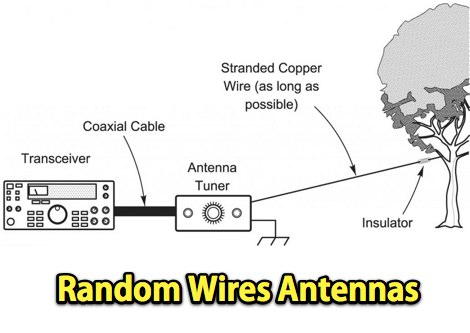 ARRL article on random wire antenna, simple antennas that can be tuned for every band, excellent solution for field day operations
 -
 W3EDP antenna assembly instructions and dimensions with pictures in this PDF File
 -
 An home made vertical dipole antenna made with simple material. The antenna has a total length of aproximately 16 feet. In this article appeared on June QST 2019, the author explain how he reached the optimal confirugation changing and adjusting the lower part of the antenna, trimming and spacing correctly the copper wire. PDF File to downloas
 -
 Antenna Rotor Control Software for Windows and Linux is a companion project to the arduino rotor controller.
 -
 RFAC Solutions specializes in providing a range of RF components, including various connector types, cable assemblies, attenuators, and filters. Their product line features common connector standards such as SMA, BNC, TNC, N-Type, MCX, and MMCX, essential for reliable RF signal paths in amateur radio and commercial applications. The company also offers high-power VHF amplifiers, catering to needs for signal boosting in specific frequency ranges. Their offerings extend to dust caps and adapters, which are crucial for maintaining the integrity and versatility of RF systems. The focus on supplying components from South Korea suggests a commitment to specific manufacturing standards and supply chain practices. This resource details a vendor's product scope, useful for hams sourcing specific parts for shack builds or antenna projects. Jeff is listed as a contact for inquiries.
 -
 Windows program for analyzing vertical antennas. This program shows the resistance and reactance to be expected looking into a cylindrical metallic tower over a perfect ground. It gives a useful approximation of the values to be expected in a real-world situation.
 -
 Selecting appropriate cabling for amateur radio installations, whether for antenna feedlines, control lines, or station wiring, is critical for optimal performance and safety. This resource provides access to a manufacturer specializing in a broad range of electronic and electrical cables, including options suitable for various ham radio applications. Their product line encompasses standard and custom cable solutions, designed to meet specific operational requirements for both indoor shack setups and outdoor antenna systems. The company emphasizes _proven quality_ and compliance, with products certified by the Canadian Standards Association (CSA), Underwriters Laboratories (UL), and Intertek (ETL). Their quality management system is registered to _ISO 9001:2015_, ensuring consistent product standards. They offer competitive pricing and utilize AI-logistic tools for reliable on-time delivery, serving customers globally with technical support. Access to detailed technical specifications and an online quote tool is available for registered site members, facilitating precise cable selection for projects requiring specific impedance, shielding, or environmental ratings.
 -
 Optimizing a G5RV or ZS6BKW multiband wire antenna for HF operation often involves addressing common SWR issues and understanding feedline characteristics. This resource chronicles the construction and performance evaluation of a G5RV, initially built for 80m, 40m, 15m, and 10m bands, by a newly licensed Foundation operator. The author details the selection of materials, including 3.5 mm stainless steel wire for the doublet arms and enameled copper wire for the open-wire feeder, and the initial decision to omit a balun based on common online information. The narrative highlights the initial disappointing performance, characterized by high receive noise and poor signal reports on 80 meters, despite the transceiver's internal ATU achieving a 1:1 match. This led to experimentation with a coax current balun and further research into G5RV myths, such as SWR claims and the necessity of a balun. The author then describes modifying the antenna to the ZS6BKW configuration, which involves specific changes to the doublet and feedline lengths, and integrating a 1:1 current balun wound on a ferrite toroid. The modifications resulted in improved reception and transmit performance across the bands.
 -
 Industrial Communication Engineers (ICE) was a manufacturer specializing in **RF components** and solutions for amateur radio and commercial applications. Their product line included a range of RF parts, various types of filters, and RF switching products designed to enhance station performance and mitigate interference. These components were critical for hams engaged in contesting, DXing, or general operating, providing means to improve signal integrity and manage complex antenna systems. The company's offerings addressed common operational challenges such as RFI and TVI, with products like **low pass filters** and antenna filters. While the specific technical specifications of their product range are no longer available, such components typically provided significant attenuation of unwanted harmonics and out-of-band emissions, crucial for maintaining a clean signal and preventing interference with other electronic devices. The current status indicates the domain is for sale, suggesting the manufacturing operations have ceased.
 -
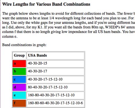 An interesting article on random wire antennas, and how to choose the optimal lenghts for multiband operations.
 -
 Article on mobile antenna mounting methods by Firestik
 -
 An off centre fed dipole, with 10 feet of vertical radiator. It needs no tuner on 40m, 20m and 10m by M0UKD
 -
 For amateur radio operators engaged in **radio direction finding** (RDF) and **transmitter hunting** (T-hunting) activities, this resource provides a catalog of printed circuit boards (PCBs) for constructing various DF and foxhunt-related projects. The offerings include PCBs for 80-meter fox transmitters and receivers, UHF fox transmitters with audio recording capabilities, and several designs for general-purpose radio direction finders. Specific projects like the "Simple 80M ATX-80 Transmitter" and the "N0GSG DSP Radio Direction Finder" are listed, along with attenuator boxes and specialized components for Doppler DF systems. The catalog details PCBs for projects published in prominent amateur radio magazines such as *73's*, *CQ*, *QST*, and *PE*, indicating their origin and design pedigree. For instance, the "Montreal Fox Controller" is sourced from the *Homing-In* column by Joe Moell, K0OV. The resource also lists components for advanced Doppler DF systems, including main boards, LED display boards, and antenna switch boards, with options for programmed PIC microcontrollers. Pricing for each PCB is provided, allowing hams to acquire the necessary components for their DIY RDF endeavors.
 -
 The _National Contest Journal_ (NCJ) serves as a dedicated resource for amateur radio contesters, providing in-depth articles, operational strategies, and technical insights. Published bimonthly by the ARRL, it covers a wide array of contesting topics, including antenna systems, station optimization, operating techniques, and rule interpretations for major events like the NA Sprint and various QSO Parties. The journal aims to enhance the competitive edge of participants across all skill levels, from casual operators to serious multi-operator teams, by sharing experiences and data from high-scoring stations. NCJ content frequently includes detailed analyses of contest results, offering breakdowns of scores, participant statistics, and comparisons of operating strategies. Readers can find practical advice on improving their contest performance, such as optimizing logging software usage or maximizing **run rates**. The journal also features columns on specific contest modes like RTTY and provides updates on rule changes and upcoming events, helping contesters prepare for future competitions and achieve better results, often leading to **top 10** finishes in their respective categories.
 -
 About longwire antennas, technically to be a true longwire an antenna needs to be at least one wavelength long, but common use of the term by Hams is for any random wire length that is end fed.
 -
 A Loop Fed Array Yagi antenna for 50 MHz featuring 11 dBi gain and 23 f/b ratio. In this excellent page the author even includes a detailed drawing in DWG format, with element lenght and spacing measures, in a separa file a full list of material list needed to build this yagi antenna including source and price, the EZnec file for this antenna plan, and a lot of pictures of this LFA Yagi for 50 Mhz. A ten page PDF file containing all infos, is also available to download.
 -
 One point eight MHz to 30 MHz is the operational bandwidth for this 4:1 Ruthroff voltage balun, designed to interface an unbalanced T-Match network with a balanced antenna system. The project details the construction using a _T200-2_ powdered iron toroid core, tightly wrapped in PVC electrical tape for insulation, and wound with 17 double bifilar turns of 1.25mm enamelled copper wire. This outboard balun offers flexibility, allowing hams to trial various baluns based on antenna system and impedance characteristics, rather than integrating it directly into the tuner. The resource includes a schematic of the balun, a wiring diagram showing winding connections, and a table suggesting alternative toroid cores like the T80-2 or T400-2 with corresponding winding counts. Component sourcing is straightforward, listing items such as the _Amidon_ T-200-2 core, SO-239 connector, and a sealed polycarbonate enclosure from Jaycar. Performance evaluation was conducted using an _AIM 4170C_ antenna analyser, demonstrating efficient 1:4 voltage transformation across the specified HF spectrum. Further efficiency tests involved measuring RF power loss at various frequencies, revealing minimal loss—less than 0.7 dB from 3.6 MHz to 30 MHz, and only 2.0 dB at 1.8 MHz. These measurements, performed under ideal 50-ohm conditions, confirm the balun's effectiveness as a low-loss interface for multi-band antenna systems. The page also links to several other balun and unun projects, including 1:1 current and voltage baluns, and 9:1 voltage ununs, providing a broader context for impedance matching solutions.
 -
 Optimizing the ZS6BKW antenna for full HF band coverage often requires specific modifications beyond its standard configuration. This resource details several enhancements, beginning with a simple series capacitor to improve 80m SWR, a technique W5DXP found effective for permanent installation due to its minimal impact on higher bands. Further improvements include a 10-inch parallel open stub for 10m resonance, shifting the frequency to 28.4 MHz with an SWR of approximately 1.8:1, a practical solution for Technician class operators. The document then explores a switchable matching section, adding or subtracting one foot of ladder line at the 1:1 choke-balun, which significantly impacts higher frequency bands and eliminates the need for a tuner on 17m. W5DXP's _AIM-4170D_ antenna analyzer measurements confirm these effects. More advanced modifications involve a parallel capacitor for further 80m SWR reduction, requiring remote switching for multi-band operation, and relay-switched parallel capacitors at specific points on the 450-ohm matching section to achieve low SWR on 60m, 30m, and 15m. These detailed steps, including _Smith chart_ analyses for the challenging bands, aim to transform the ZS6BKW into a truly all-HF-band antenna, reflecting W5DXP's practical experience in antenna tuning.
 -
 Memorandum on the Beverage Wave Antenna for Reception of Frequencies in the 550 - 1500 Kilocycle Band", FCC Report 9.2.1, by Benjamin Wolf and Adolph Andersen
 -
 SWR (standing wave ratio), is a measurement of how efficiently your antenna system will radiate the power available from your radio. In simple terms, your radio would like to radiate all of its power, but can only do so if the other components cooperate
 -
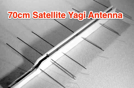
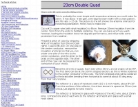 probably the most simple and inexpensive antenna you could make for 23cm.