Search results
Query: design frequency
Links: 245 | Categories: 5
-
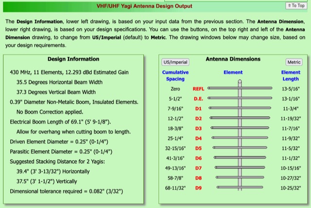 Design your VHF UHF Yagi antenna online, a JavaScript enhanced web page that implements the design of an antenna for 2m and 70cm bands. This page offers a streamlined experience for Yagi antenna design enthusiasts. It assumes prior knowledge of Yagi design principles, minimizing distractions with a user-friendly interface. Equipped with essential equations, it provides instant design feedback. Red font warnings indicate design limitations, ensuring practical results. Constraints include Gain (11.8-21.6 dBd) and Boom Length (2.2-39 wavelengths), with additional frequency-dependent restrictions noted in input fields.
 -
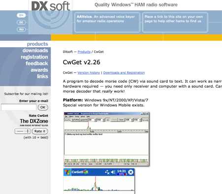 CwGet v2.55 is a software application for amateur radio operators designed to decode Morse code (CW) signals into text using a standard computer sound card, eliminating the need for specialized hardware. The program features a customizable interface with a spectrum display for visualizing signal frequencies and peaks, an oscillogram for monitoring signal presence and setting detection thresholds, and a received symbols window for displaying decoded text. Key functionalities include Automatic Frequency Control (AFC) to lock onto signals, adjustable FIR and IIR filters for noise reduction, and a burst filter to mitigate short noise impulses. It also supports automatic CW speed detection, multiple character sets, and the ability to record and replay received audio. Integration with logging software like AALog is facilitated through double-click word transfer, and transceiver frequency control is possible via the Omni-Rig interface, allowing for automatic tuning of the radio's VFO or RIT. The multi-channel decoder feature can simultaneously decode up to five strong signals within a 1600 Hz bandwidth, displayed in a separate Multi-RX Window with an adjustable squelch. CwGet also offers the capability to decode signals from pre-recorded WAVE files and can function as a narrow-band sound DSP filter for aural decoding. This is a commercial version and it has been tested on latest MS Winows versions.
 -
 The G5RV antenna, with an overall length of **31.10m (102ft)**, functions as a 3/2-wave on 20 meters when installed horizontally at 12m (39ft), exhibiting a resonant frequency of 14.150MHz and an approximate resistance of 80 ohms. Its 10.36m (34ft) stub line, designed as a 1/2-wave on 14.150MHz with a 0.97 velocity coefficient, acts as an impedance transformer across other bands, aiming for multiband operation without traps. On 20m and higher frequencies, the G5RV demonstrates improved gain compared to a standard dipole, attributed to the _collinear effect_ from multiple 1/2-waves along the wire. The original design sought a multiband solution for limited spaces, often requiring an Antenna Tuning Unit (ATU) for effective operation across bands like 80, 40, 30, and 20m, particularly with modern solid-state PAs. Variants, such as the F8CI modification, incorporate a 1/4 current balun at the stub line's base for symmetrical-to-asymmetrical transition, known as a _remote balun_. Proper flat-top or inverted-V installation is critical for maintaining symmetry and collinear gain, with inverted-V apex angles below 120° progressively diminishing higher-band performance.
 -
 This guide provides step-by-step instructions for constructing a tin can waveguide antenna, commonly known as a cantenna, for enhancing WiFi signal range. The project is budget-friendly, costing under $5, and utilizes easily accessible materials like a food can and basic electronic components. The design is suitable for 802.11b and 802.11g wireless networks, operating within the 2.4 GHz frequency range. To start, gather the necessary parts including an N-Female chassis mount connector, nuts, bolts, and a suitable can. The assembly process involves drilling holes in the can for the connector and mounting the probe. The guide emphasizes the importance of can dimensions and placement for optimal performance, encouraging experimentation for best results. This project is ideal for amateur radio operators and DIY enthusiasts looking to improve their wireless connectivity without significant investment. Safety precautions are advised, as the author does not hold electrical engineering credentials. Users are encouraged to take responsibility for their equipment and ensure proper assembly. With this simple yet effective antenna, users can extend their WiFi coverage and enjoy enhanced connectivity.
 -
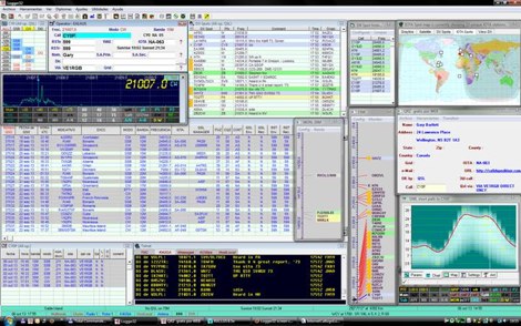 Logger32 is a well-established amateur radio logging program designed primarily for DXers who require a flexible and data-driven logging environment. The software maintains a comprehensive logbook database capable of handling large volumes of QSOs while offering detailed tracking of DXCC entities, awards, and band/mode statistics. One of the core strengths of Logger32 is its DX cluster integration. The program connects to telnet DX clusters and displays spots in real time, with filtering options by band, mode, country, or callsign. The cluster window can automatically highlight needed DXCC entities, band-fills, or new modes based on the operator’s log. Logger32 also provides rig control through CAT interfaces, supporting a wide range of transceivers via serial or USB connections. When properly configured, frequency and mode are automatically captured in the log entry window. The software supports digital mode integration through external applications and can exchange information using standard interfaces. Another important feature is its award tracking system, including DXCC, WAS, IOTA and other common amateur radio awards. The program calculates worked, confirmed, and needed entities with detailed reports. Logger32 supports ADIF import and export, allowing interoperability with other logging systems. It also includes QSL management, with tracking for bureau, direct, and electronic confirmations such as LoTW or eQSL when configured. Overall, Logger32 remains a technically capable logging solution focused on DX tracking, cluster awareness, and detailed statistical analysis of operating activity.
 -
 Sixty-four years of operating experience inform Glynn E. "Buck" Rogers Sr., K4ABT's, insights into the J-Pole antenna, which he describes as a direct descendant of the _Windom_ or _ZEPP_. His first article on the J-Pole appeared in HRC magazine in 1958, and he has since published numerous pieces in publications like CQ Magazine, consistently referring to the J-Pole as a Windom with a folded-back short section forming the parasitic element. He emphasizes that both the Windom and J-Pole are powerful multi-band antennas, performing exceptionally well at harmonics of their fundamental design frequency, and advocates for 50-ohm coaxial cable with a _BALUN_ at the feed-point to avoid RF energy losses. K4ABT details the J-Pole's features, noting its ease of erection, lack of radials, low angle radiation, greater bandwidth, and immunity to terrestrial noise. He highlights its suitability for local nets and distant repeaters, claiming more gain and durability than most ground planes, and its ability to meet stealth antenna requirements. The guide provides specific dimensions for 2-meter (145.000 to 146.000 MHz) and 6-meter (50.500 to 51.500 MHz) J-Pole antennas, including measurements for the long driven element, short tuning stub, and spacing. The construction section illustrates a modified feed technique using an SO-239 chassis-mount coax connector soldered into a copper tee, deviating from the usual hose clamp method. The author also discusses the use of _EMT_ (electrical metallic thin-wall conduit) as an alternative to copper in earlier days. He cautions against building a 75-meter J-Pole due to its impractical length, reinforcing the antenna's optimal application for VHF and UHF bands.
 -
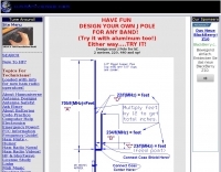 The J-Pole Antenna Design Calculator, developed by K4ABT, G.E. "Buck" Rogers Sr., facilitates the rapid determination of J-Pole antenna dimensions for various amateur radio bands. Users input their desired operating frequency to generate specific measurements, enabling construction for HF, 2 meters, 220 MHz, 440 MHz, and higher frequencies. The tool supports designs using materials like aluminum or copper, offering flexibility for homebrew enthusiasts. Operational guidance includes recommendations for integrating a **choke balun** near the feedpoint to mitigate RF on the feedline, thereby improving SWR accuracy. For 2-meter operation, a suggested choke configuration involves four turns of coax with a 5-inch diameter, positioned within 3 to 4 inches of the feedpoint. Additional builder hints detail cost-effective construction methods, such as utilizing 1/2-inch EMT conduit and 1/4-inch soft copper for the 'J' section. The resource also references K4ABT's articles in CQ Magazine, specifically "The Packet Users Notebook," providing further technical context and design principles for antenna builders.
 -
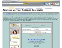 This basic calculator is designed to give the aproximate length (height) of a particular vertical antenna, for the frequency and wavelength chosen.
 -
 Details the construction of a J-vertical antenna specifically for the 10-meter band, offering a practical alternative to a _Slim Jim_ design for 28 MHz. The resource outlines the use of aluminum tubing for the half-wave vertical section and coaxial cable for the quarter-wave matching section, providing specific calculations for element lengths based on frequency and coaxial cable velocity factor. It contrasts the performance of the J-vertical with center-fed dipoles and end-fed verticals, noting superior results in previous comparisons. The article further presents a more recent iteration of the J-vertical, constructed using a fiberglass pole and insulated wire, with updated dimensions for 28.8 MHz. It includes practical advice on weatherproofing connections and securing the antenna for durability against adverse conditions, referencing the survival of an original _J Vertical_ during 110 MPH winds in 1987. The SWR performance is reported as 1.1:1 at 28.6 MHz, maintaining below 1.5:1 across 28.3 to 29 MHz.
 -
 The **DF9CY Three-Element Antenna for 28 MHz** details the modification of a commercial PAN International CB antenna to optimize its performance for the 10-meter amateur radio band. This resource provides specific design parameters, including a design frequency of 28.300 MHz, a usable bandwidth of 600 kHz, and a return loss better than 20 dB centered at 28.270 MHz. It also specifies a gain exceeding 7.5 dBi and a front/back ratio greater than 20 dB. The feeding mechanism utilizes a **gamma match**, with setup instructions provided for its positioning. Modifications involved shortening each element's end by 40 mm, a straightforward process due to existing screw holes. The author also recommends replacing the original screws with V2A stainless steel hardware to prevent oxidation and upgrading the SO239 connector to an N-connector for improved reliability. EZNEC simulation files are available, showing azimuth and elevation diagrams with good front-to-back ratio and around 10 dB vertical attenuation. The antenna has been in service since October 1998, demonstrating good performance with 90 watts and even 750 watts, facilitating contacts with all continents from a modest 9-meter height.
 -
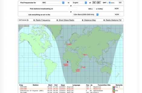 Monitoring shortwave broadcast stations effectively requires accurate schedule information to identify transmissions. This online utility offers a straightforward, graphical interface designed to search for and display current shortwave radio broadcasting schedules. Users can precisely filter results by frequency, specific language, broadcaster, time of day, and even by shortwave band, which simplifies the process of pinpointing desired content. The database, last updated on March 26, 2023, details station callsigns (e.g., BBC), start and end times in UTC, days of the week, broadcast language, transmitter power in kilowatts, and azimuth. Crucially, it includes the precise geographical coordinates of transmitter sites, such as Woofferton in the UK or Al Seela in Oman. This data is invaluable for predicting signal paths and optimizing antenna direction for improved reception, a key consideration for serious SWLs. For instance, a search for BBC English broadcasts at 21:04 GMT quickly reveals multiple active frequencies like 17780 kHz from Woofferton, offering a clear overview of current transmissions. The tool processes queries rapidly, returning results within seconds, demonstrating its efficiency for broadcast listening enthusiasts seeking timely information.
 -
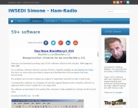 This resource provides access to the 59+ software collection, specifically highlighting the **59+ CW** module. The software enables the generation of Morse code signals for transmission through a COM port to a transceiver, or for audio output via a computer speaker, facilitating both keying and listening practice. Users can customize various parameters, including CW speed, tone frequency, dash/dot ratios, and PTT line delay, alongside defining keyboard shortcuts for common QSO fields such as callsign, QTH, name, and RST. The collection also includes the 59+ Logbook, which operates smoothly on Windows XP according to testing notes, though the CW application experienced startup issues on the same OS. The software was originally designed for older Windows operating systems, specifically Windows 95, 98, ME, and 2000. It is noted that the original idealog.net site is no longer active, and development for the 59+ suite appears to be discontinued. Analyzer and converter modules within the collection require registration and do not function in trial mode.
 -
 The RXO Unitenna, a vertical wideband antenna, offers operation across the 7-21 MHz spectrum, covering the 40, 30, 20, 17, and 15-meter amateur bands. This design focuses on achieving a low SWR across a broad frequency range, making it suitable for general HF operation without requiring an external antenna tuner for minor SWR variations. The antenna utilizes a unique loading coil and matching network to maintain efficient radiation characteristics across its operational bandwidth. Construction details within the PDF document include specific dimensions for the radiating element and the counterpoise system, which is critical for vertical antenna performance. The design incorporates readily available materials, simplifying the build process for radio amateurs. Performance graphs illustrate the SWR characteristics across the 7 MHz to 21 MHz range, demonstrating the antenna's wideband capabilities. The document also provides guidance on feedline connection and grounding considerations for optimal field deployment. This vertical antenna configuration is particularly useful for hams with limited space, offering a compact footprint compared to horizontal wire antennas.
 -
 Determining the actual need for an antenna tuner often hinges on the specific antenna and feed line configuration in use. While many hams believe a tuner is always essential, its primary role is to present a 50-ohm impedance to the transceiver, not to "tune" the antenna itself. For instance, a resonant dipole fed with _coaxial cable_ at its design frequency typically requires no tuner, as the feed line impedance closely matches the radio's output. However, operating a non-resonant antenna, or using a resonant antenna on multiple bands, frequently necessitates a tuner to manage high Standing Wave Ratio (SWR) on the feed line. The article clarifies that a tuner placed at the transceiver only matches the radio to the feed line, not the antenna to the feed line. For maximum efficiency with a non-resonant antenna, an _automatic antenna tuner_ (ATU) or a remote tuner placed at the antenna feed point is often more effective, minimizing losses in the feed line. The discussion also touches on the practical implications of SWR, noting that modern transceivers often fold back power at high SWR, making a tuner a practical necessity to achieve full output power, even if the antenna itself is not perfectly matched.
 -
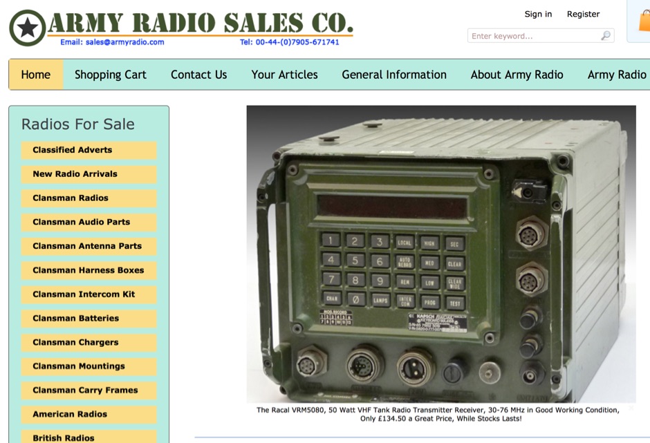 The Racal VRM-5080 VHF FM Radio Transceiver, designed for military vehicle installation, operates across the 30 to 76 MHz frequency band with 50 Watts of output power. This unit, along with other featured items like the DOM-410 Geiger Counter and the RT-524/VRC VHF Vehicle Radio Station, represents the core offerings of Army Radio Sales Co. The site provides detailed technical specifications for each product, including frequency ranges, power output, channel spacing, and operational voltage, catering to collectors and restorers of vintage military communications gear. Beyond product sales, the website serves as a repository for historical information, offering access to military radio manuals, articles, and thousands of pictures. Resources such as the SCR-694 / BC-1306 Radio Signal Corps Training Film and TM 11-2715 Installation of Radio Equipment in 1944 Jeeps are available. The platform also hosts a free classifieds section for users to advertise their military radio needs and offers insights into related military vehicle projects. Additional content includes information on the STR37E VHF Aircraft Radio Transceiver, operating from 116.00 MHz to 135.95 MHz, and the R-442/VRC VHF Vehicle Radio Receiver, covering 30-75.95 MHz. The site also features articles on topics like the Ukrainian Expedition and data plates for military Jeeps, broadening its appeal to military history enthusiasts.
 -
 Galaxy DX 47HP and DX 99V2 models are highlighted, showcasing the manufacturer's current offerings in both amateur and Citizens Band radio transceivers. The site details several amateur models, including the DX 29HP, DX 44HP, DX 55HP, DX 98VHP, DX 33HP2, and DX 94HP, catering to different operational needs and power levels. For CB operators, a range of models like the DX 2547, DX 979, and DX 929 are presented, with specific features such as _StarLite_ front panel lighting for low-light conditions, as seen on the DX 929 and DX 979. The DX 979 is noted for its compact form factor and SSB capability, making it suitable for installations where space is a constraint. Conversely, larger models like the DX 939, DX 949, and DX 959 are available for those with more room, offering features such as blue lighting and integrated frequency counters. The DX 939, for instance, combines aesthetic appeal with functional design, providing clear readouts and robust audio performance. A downloadable CB radio shopping guide is also offered, enabling users to compare Galaxy's product specifications against other radios on the market, facilitating informed purchasing decisions.
 -
 For amateur radio operators utilizing _APRS_ or requiring an external antenna for their GPS receiver, this resource details the construction of a compact, circularly polarized mobile antenna. The design is based on a classic turnstile configuration, employing two dipoles rotated 90° from each other and spaced a quarter-wavelength above a ground plane. A parallel-plate transmission line, fabricated from printed circuit board material, serves as both the connection method and mounting post for the dipoles, simplifying the feed network for circular polarization at 1.57542 GHz. The article outlines the fabrication process, starting with a 4-inch diameter hobby tin or brass base plate and #14 solid copper wire elements. It specifies using _RG-58/U_ or similar 50-ohm coax, with an 8-foot maximum length to minimize loss at the GPS frequency. The parallel-plate transmission line is constructed from two 2-inch lengths of single-sided _FR-4_ or G10 PCB material, 0.062-inch thick, with a specific 45° microwave turn cut on the active side. Final assembly involves an 8-ounce cream cheese container as a radome, and the article discusses the self-phased quadrature feed method to achieve circular polarization without a coaxial phasing line, resulting in an omnidirectional pattern suitable for GPS satellite reception.
 -
 Normal mode helix antennas offer a solution for HF mobile operators facing significant height restrictions, such as those parking in indoor garages with limited overhead clearance. This design, adapted from concepts typically applied to VHF/UHF rubber duck antennas, allows for extremely shortened HF radiators that remain effective for county hunting and general mobile operation. The resource details the construction of a 20-meter helix antenna, approximately 10 inches long, wound with #14 AWG THHN wire on a 1 1/2-inch CPVC form, mounted on a standard 3/8 x 24 antenna stud. Mark Herson, _N2MH_, shares his experience developing these antennas, including initial research from the _RSGB VHF UHF Manual_ and practical winding experiments to establish the relationship between turns and resonant frequency. He provides coil data for various frequencies, emphasizing that these measurements were taken with an _MFJ-259a_ antenna analyzer and are dependent on the vehicle's grounding system. Despite their shortened nature, N2MH confirms the antennas' operational effectiveness, citing contacts with KL1V in Alaska on 20 meters and E-skip contacts on 10 meters. The design prioritizes continuous deployment without removal, making it suitable for operators who frequently navigate height-restricted environments.
 -
 Constructing a **reduced-size coaxial Moxon rectangle** antenna for the 17-meter band is detailed, presenting a method to achieve a compact directional antenna. The resource outlines the use of RG-58/U coaxial cable for elements, enabling a substantial reduction in physical dimensions compared to traditional wire or tubing Moxon designs. It provides specific instructions for tuning coaxial elements using an **MFJ-259B antenna analyzer**, including a formula to calculate trimming lengths based on measured resonance and desired frequency. The article explains how to prepare the coaxial cable for both driven and reflector elements, specifying connections for testing and final assembly. Performance data from an MFJ-259B shows SWR readings between 1.0 and 1.2 across 18.068 MHz to 18.168 MHz, with R values from 51 to 59 ohms and X values of 0 or 6 ohms. The antenna's power handling is approximately 500 watts continuous, limited by the RG-58/U coax. Comparative receive testing against an All-Band Sterba Curtain at 50 feet indicated a 2 S-unit reduction for the coaxial Moxon at 9 feet, suggesting optimal performance at a height of 34-40 feet for a 15-18 degree take-off angle. The design achieves an electrical quarter wavelength with over 30 percent size reduction.
 -
 A Linux based FFT spectrum analyzer designed for time-frequency browsing and scientific data visualization. Oscilloscope waveform, statistical histogram, accumulated spectral trace,Weak Signal reception, continuos data logging, FFT Analyzer and specialized measurement windows.
 -
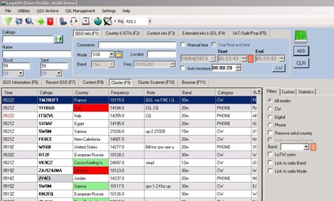 Log4OM is a free logging software designed for amateur radio operators who require an integrated environment for station management and QSO logging. It is widely used by DXers due to its strong database capabilities and its integration with common online services. The program uses a structured SQL database and supports large logbooks without noticeable performance degradation. One of its key features is **CAT Control**, which allows direct communication with many transceivers for automatic frequency and mode detection. The **DX Cluster Client** provides real-time spotting with filtering and band/mode tracking, helping operators quickly identify new DX opportunities. Log4OM integrates with several external confirmation systems. Built-in support for **Logbook of The World (LoTW)** and **eQSL** allows automatic upload and download of confirmations. The software also includes **Award Tracking**, enabling operators to monitor progress toward DXCC and other award programs directly from the log. Additional capabilities include **Callbook lookup** via services such as QRZ, **ADIF import/export**, and customizable **QSL management** for both electronic and paper cards. The interface is modular, with panels that can be arranged depending on operating preferences. Log4OM does not include integrated digital mode engines, so digital operation normally relies on external programs such as WSJT-X or FLdigi connected through standard interfaces. Overall, Log4OM provides a comprehensive logging environment suitable for both casual operation and serious DX chasing, with a feature set comparable to many commercial logging applications.
 -
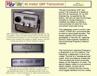 The project details modifications to an ARK-40 QRP CW transceiver kit, specifically replacing its original thumbwheel frequency selectors with a **BASIC STAMP BS-II microcontroller** and an optical shaft encoder. The redesigned control circuitry outputs a BCD code to the ARK-40's synthesizer, enabling more convenient knob-type tuning. This modification significantly alters the user interface, moving from discrete frequency selection to continuous tuning. Operating frequency is presented on an LCD readout, offering two distinct display modes: a "bandspread dial" mode that simulates an analog dial scrolling across the display in 1 kHz increments, and a conventional digital readout with 100 Hz resolution. Pushing the main tuning knob toggles between these modes, providing both rapid band traversal and fine-tuning capabilities. The software for the BASIC Stamp is written in P-Basic, addressing the challenge of accurate analog dial simulation. Physical modifications include fabricating a custom PC Board for the STAMP, mounting it with an L-bracket to the optical encoder, and creating a new front panel. The front-mounted speaker was relocated to accommodate the new tuning knob and display, transforming the **ARK-40 transceiver** into a more user-friendly rig with its built-in CW keyer and 5 watts of power.
 -
 The directory lists several files, including `_template1.html` and `_template2.html`, last modified in 2006 and 2004 respectively, indicating a historical web project. Key scripts like `hfcc_cfm.pl` and `index.cgi`, updated in 2011, suggest a **CGI-based application** for searching shortwave broadcast schedules. The presence of `_template1.tpl` and `_template2.tpl`, both modified in 2015, points to a templating system for dynamic content generation. The file `hfcc_create-fill_mys..>` (likely `hfcc_create-fill_mysql.pl`) implies interaction with a database, possibly MySQL, for storing and retrieving **HFCC (High Frequency Co-ordination Conference)** schedule data. The `lang.cgi` script, last updated in 2002, suggests early support for multilingual interfaces or language-specific content delivery. The `q.txt` file, a small 804-byte text file, could be a query log or a simple data file. The overall structure indicates a system designed to process and present shortwave broadcast information, likely by querying a database of scheduled transmissions on various HF frequencies. The file modification dates suggest the project was actively developed and maintained over a period spanning more than a decade, with core components last updated around 2011 and templates in 2015.
 -
 Presents a crystal-controlled CW transmitter design for the 40-meter band, delivering 5 to 7.5 watts output power. The circuit innovatively employs an _IRF510_ power MOSFET in the final amplifier stage, diverging from conventional bipolar transistors. This design offers high gain, nearly 90% efficiency, and robust resistance to high SWR, allowing 30-second key-down operation into an open circuit without damage. A critical aspect is the precise adjustment of the MOSFET gate bias via a 10K trimmer pot, _R10_, to maintain quiescent current between 5 and 10 mA, preventing thermal runaway inherent to bipolar devices. The prototype was constructed on a _Radio Shack universal board_ and achieved immediate operational success. The design requires a 15-volt Zener diode to protect the MOSFET gate from overvoltage. Component sourcing information is provided, including specific crystal frequencies (7.040 MHz or 7.122 MHz) available from _Dan’s Small Parts & Kits_ or Doug Hendricks. The fixed frequency can be slightly adjusted with a trimmer capacitor. A complete bill of materials, including resistor values, capacitor types, toroid specifications, and transistor part numbers, is detailed, alongside a clear schematic diagram.
 -
 The KD6WD Moxon Antenna Project details the construction of 50-ohm two-element wire beam antennas, specifically Moxon rectangles, for the 10, 15, 17, and 20-meter bands. It utilizes AC6LA's software for critical measurement calculations (A-E) based on center frequency and wire size. Construction involves 16-gauge silver-coated copper wire, 16-foot telescoping fiberglass crappie fishing poles as spreaders in an "X" configuration, and various hub designs including aluminum tubing or PVC joints. A 1:1 current balun is used at the feedpoint, with wire nuts for connections, often achieving a 1:1 SWR across the design band. The project highlights practical applications, such as running a kilowatt into the antennas for greyline DX contacts, consistently yielding excellent signal reports. Comparisons to quad loops show 4 to 5 S-unit improvements in both receive and transmit. The Moxon design, according to L.B. Cebik's analysis, offers superior forward gain and front-to-back ratio among wire beams. The author notes a "DX-Vane" effect where a freely suspended Moxon automatically points to the strongest DX signal. Attempts at dual-band operation (17/20 meters) with a single feed were unsuccessful, reinforcing the Moxon's monoband nature, with EZNEC plots provided for a 17-meter Moxon at 30 feet.
 -
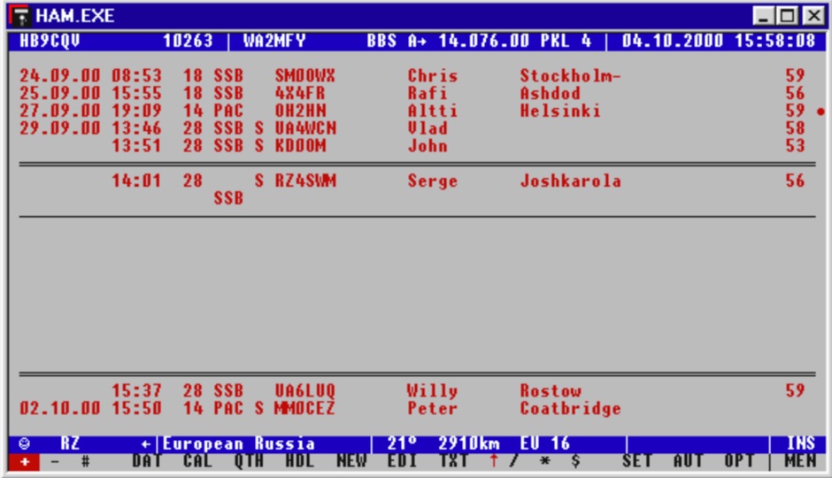 Facilitates efficient logging of amateur radio contacts, offering a robust solution for hams managing their station activities. The software integrates _CAT control_ capabilities, allowing direct interfacing with popular transceivers from manufacturers like Yaesu, Icom, and Kenwood. This feature streamlines the logging process by automatically capturing frequency, mode, and other QSO details directly from the radio, reducing manual entry errors and improving operational efficiency during contests or DXing. _HAM-LCT_ includes a comprehensive database, enabling users to store and retrieve contact information, QSL data, and other relevant details for each QSO. The program supports various operating modes and provides tools for searching and filtering log entries, which is beneficial for award tracking and station analysis. Its design focuses on providing a user-friendly interface for everyday logging tasks. While the original author, _HB9CQV_, has discontinued development of HAM-LCT in favor of a newer logging application, this version remains available as a functional freeware option for Windows users seeking a dedicated logbook with integrated rig control.
 -
 RT Systems provides programming software for Windows operating systems, supporting a wide range of amateur radio transceivers, scanners, and receivers from manufacturers like Icom, Yaesu, and Kenwood. The software facilitates memory management and radio settings configuration, often surpassing OEM software in user-friendliness and functionality. Their **USB programming cables**, featuring **FTDI chipsets**, are noted for reliable operation, even in virtualized environments like Windows ARM on a Mac, where OEM cables might fail. Users report that RT Systems software simplifies the often complex process of radio programming, making it less arduous than manual entry. The availability of integrated frequency databases is a significant advantage. The software and cables are frequently cited for their long-term reliability, effective customer support, and thoughtful hardware design, which collectively address common real-world programming challenges for various radio models, including the Icom ID-880H and Anytone 878.
 -
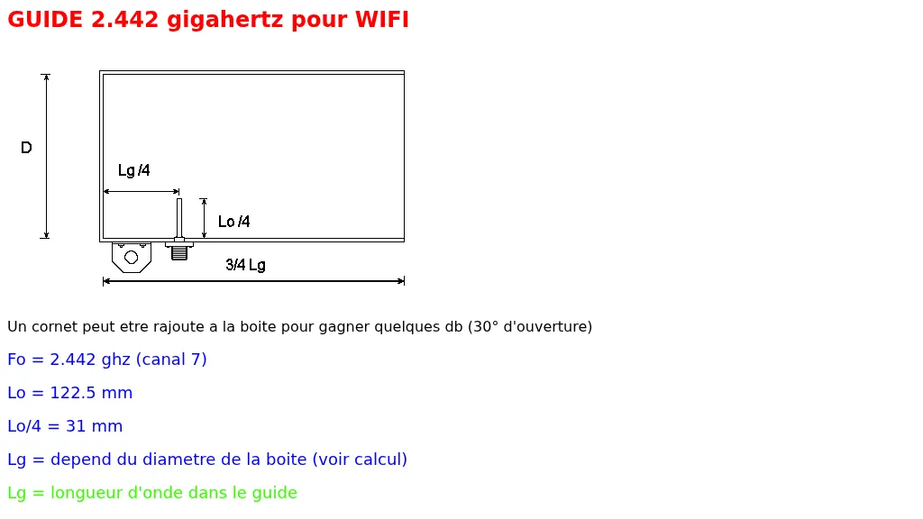 Demonstrates the construction of a 2.4 GHz horn antenna, specifically designed for WiFi applications, with the potential to add several dB of gain. The resource focuses on the critical dimensions and calculations required for proper operation, including _wavelength_ (Lo) and guide wavelength (Lg) based on the operating frequency (Fo) of 2.442 GHz, corresponding to channel 7. The guide provides a table of European WiFi frequencies, ranging from 2.412 GHz to 2.477 GHz, highlighting the specific channel 7 as the design target. It details how the length of the waveguide (Lg) depends on the diameter of the enclosure, offering a practical approach to antenna construction. This project outlines the necessary measurements like Lo/4 at **31 mm** and provides a link to an external calculator for further design specifics. The horn design aims for a 30-degree beamwidth, making it suitable for focused signal transmission or reception.
 -
 The **NW3Z** optimized wideband antenna designs, originally presented at Dayton 2001, detail Yagi configurations for the 20-meter, 15-meter, and 10-meter amateur radio bands. This resource provides access to the design files, likely containing critical parameters such as element spacing, element lengths, and boom dimensions, which are essential for replicating these directional antennas. The designs focus on achieving wide bandwidth, a desirable characteristic for contesters and DXers operating across a significant portion of each band. The content specifically references "nw3z-Antenna-DesignsDownload," indicating that the core information is available as a downloadable file, presumably in a format suitable for antenna modeling software or direct construction. Such files typically include **NEC models** or similar data, allowing for performance analysis and optimization before physical construction. The emphasis on "optimized wideband" suggests design considerations for SWR bandwidth and gain characteristics over a broader frequency range than typical narrow-band Yagis. The resource serves as a direct source for specific, proven antenna designs from a known amateur radio antenna designer, offering practical data for hams interested in building high-performance Yagi arrays for HF.
 -
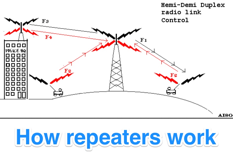 Illustrates the fundamental principles of radio repeater operation, detailing how different duplex configurations overcome signal limitations in varied terrains. It begins by contrasting _simplex_ communication, where all units share a single frequency, with more complex systems designed for extended range and specialized applications. The resource systematically presents each mode, from basic base station setups to advanced multi-frequency configurations. The content specifically covers hemi-duplex systems, often used in commercial dispatch, where the base station transmits on one frequency and mobiles on another, without rebroadcast. It then progresses to semi-duplex repeaters, the most common type in amateur radio, which automatically retransmit received signals on a different frequency. The explanation extends to demi-duplex and hemi-demi-duplex systems, which incorporate multiple control links for enhanced operational flexibility and secure communications, as seen in public safety applications. Finally, the resource clarifies full-duplex repeater systems, exemplified by cellular networks, where simultaneous two-way communication is achieved through distinct transmit and receive frequencies for each direction. The visual aids, including **9 distinct figures**, effectively demonstrate the signal paths and frequency assignments for each operational mode, providing a practical understanding of repeater architecture.
 -
 The resource details the construction and performance of a dual-band 40/30 meter _Moxon_ antenna, evolving from an initial single-band 30-meter design that failed in a storm. It specifies materials such as four 10-meter fishing rods, galvanized iron TV antenna support pipes, 1mm diameter PVC-covered copper wire, and a piece of 75-ohm TV satellite cable for feedline. The document outlines the iterative design process, including initial resonance measurements of 9.9 MHz for 30 meters and subsequent recalculations to shift the center frequency by 300 kHz using _Moxon software_. Initial testing on a roof yielded SWR readings of 1.4:1 at 7.200 MHz and 1.5:1 at 10.280 MHz. After installation atop a 30-meter tower, the final SWR measurements were 1.1 at 7.130 MHz and 1.4 at 10.230 MHz, with a notable 30 dB front-to-back ratio on 40 meters. The 30-meter performance, while good, showed a front-to-back ratio of approximately 15 dB, suggesting a slightly high resonance. The antenna's placement on a 700-meter hill, with a significant ground drop in certain directions, is noted as a potential factor in its excellent DX performance, enabling daily contacts with the USA West Coast on 30 and 40 meters with 100 watts.
 -
 Over 45 years of amateur radio experience inform the homebrew projects detailed on this personal website, with a particular focus on microwave frequencies. The site showcases a 24 GHz transverter and a more recent 47 GHz transverter, demonstrating practical construction techniques for extreme high-frequency operation. These projects often involve custom circuit design and careful component selection to achieve stable performance at millimeter-wave bands. Key projects include a _harmonic converter_ for frequency measurement and a tracking spectrum analyzer, essential tools for microwave experimenters. The site also documents a CW sidetone generator and a TX/RX sequencer, illustrating fundamental building blocks for radio equipment. Details on a digital frequency meter and an S-meter/dBm meter provide insights into test equipment construction. Specific achievements, such as a **24 GHz** tropo QSO with DK3SE in 2021, highlight the operational success of these homebrewed systems. The content reflects a long-standing dedication to self-sufficiency in amateur radio, providing practical examples for those interested in building their own gear.
 -
 MoxGen is a **Windows** application designed to calculate dimensions and generate antenna model files for 50-ohm **Moxon Rectangle** antennas. Users input the desired design frequency in MHz and the wire size (AWG or diameter in inches/mm), and the software outputs the precise element lengths, spacing, and overall dimensions required for construction. It also creates a .maa file compatible with EZNEC, enabling further analysis and optimization of the antenna's performance characteristics. The software provides a visual representation of the Moxon rectangle, displaying key parameters such as gain, front-to-back ratio, and SWR at the design frequency. This allows radio amateurs to quickly assess the potential performance of their proposed antenna before physical construction. The generated EZNEC model facilitates detailed pattern analysis, impedance matching, and interaction with surrounding structures, proving useful for both initial design and fine-tuning.
 -
 A PIC16F876 microprocessor-based digital SWR/WATTmeter project provides automatic operation across the 1.8 to 60 MHz frequency range. This design displays both SWR and P.E.P. power values, incorporating a bar graph on the second LCD line for instantaneous power tracking. The directional coupler utilizes a single-wire coil on a ferrite FT50-43 toroid, balanced with a 60 pF trimmer, and employs 1N5711 Schottky diodes for detection, ensuring linearity and a power range of 5 to 120 W. The software, developed by IW3EGT, compensates for diode voltage drop for precise readings, updating power every two seconds for stable display of modulated carriers, while the bar graph updates ten times per second for near real-time feedback. Calibration involves two phases: adjusting the directional coupler for minimum SWR on a 50-ohm dummy load at 28 MHz, and calibrating the microprocessor system by inputting a calculated power value (Power (Watt) = (Vout + 0.5)^2 / 100) at 14-21 MHz. The project includes PCB layouts for both the directional coupler (two-layer copper board) and the PIC module (single-sided), with specific instructions for component placement and shielding to prevent RF interference. The design allows for modification of power reading capability by varying the number of turns in the coupler coil, catering to different power levels.
 -
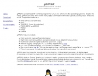 gMFSK, a Gnome Multimode HF Terminal, provides a comprehensive software solution for digital conversational modes on HF bands within Linux and Unix-like operating systems. The application facilitates sending and receiving various digital modes, including MFSK (MFSK16 and MFSK8), RTTY, THROB (1, 2, and 4 throbs/sec), PSK31 (BPSK and QPSK), PSK63, and MT63. It leverages the computer's soundcard for transceiver interfacing, performing all digital signal processing on the main CPU. The software features a multimode waterfall display incorporating waterfall, spectrum, and scope views, enabling _point-and-click tuning_ of decoded signals. Remote logging capabilities are supported via SysV IPC, with integration for logging applications like Xlog. PTT control is managed through serial or parallel port lines, and rig control is implemented using the _Hamlib_ library, allowing for real-time frequency display and transceiver manipulation. Fixtext macros can incorporate variables and command-line output. Distributed under the GNU General Public Licence, version 2, gMFSK requires Gnome libraries and FFTW 2.x libraries for operation, even without a full Gnome desktop environment. The software's design ensures compatibility with any soundcard supported by the operating system.
 -
 Details the construction of a portable _Moxon_ antenna optimized for the 2-meter band, utilizing readily available materials like 6.5 mm aluminum elements and a 15x15 mm TV boom. The design emphasizes ease of assembly and portability, making it suitable for field operations. Performance specifications derived from MMANA modeling indicate a forward gain of **6.3 dBi** and a front-to-back ratio of **15 dB**. Lateral attenuation is reported at 40 dB, with a minimum SWR of 1.1 at 144.300 MHz, confirming efficient operation within the target frequency segment. The antenna is lightweight at 500 grams, quickly assembled in approximately two hours, and disassembles into a compact 40x15x8 cm package. Direct feeding with RG-58 C/U or KX-15 coaxial cable via a BNC connector simplifies deployment.
 -
 Frequency Filer is database program designed for people who use a great many different radio frequencies. It is primarily intended for amateur radio operators, short-wave listening enthusiasts and scanner users. The program makes it easy to keep all of your important frequency information in one place, displayed in a logical format to facilitate easy retrieval. Frequency information can be displayed as a list and can be viewed on a world globe. Other features include easy data backup and custom field names. Included is database import utility that can be used as a general file conversion utility. The globe display can also be used as general geographic aid for countries, cities, states, rivers, and lakes. You may even find your home town. Windows Shareware
 -
 Constructing an HF End-Fed Half-Wave (EFHW) vertical antenna, the resource details the winding of a monoband matching unit, inspired by _AA5TB_, designed to provide a 50 Ohm impedance match without a ground plane or antenna tuner. It specifies the use of a _T200-2_ ferrite core for the transformer, outlining the 13-turn secondary and 2-turn primary winding process with enamelled copper wire. The document also describes the integration of a coax capacitor, whose length is critical for tuning and varies by band, with specific starting lengths provided for 20m, 17m, 15m, 12m, and 10m operation. The practical application section guides the builder through tuning the antenna using an antenna analyzer, emphasizing the iterative process of spacing secondary windings and trimming the coax capacitor to achieve resonance at the desired band frequency. It highlights the antenna's low angle of radiation, beneficial for DX, and claims up to 2 S-points improvement over a _G5RV_ or similar doublet when used as an omnidirectional vertical. A comprehensive shopping list, including specific part numbers from _Rapid Electronics_, is provided, along with advice on selecting fiberglass fishing poles for support and suitable antenna wire.
 -
 Mirko Pelcl's extensive radio collection features numerous historical transceivers and receivers, with a significant focus on military communications gear. The collection includes notable examples such as the Wireless Set No. 19, various Cold War-era military radios, and even a rare WWII spy radio utilizing a Loewe 3NF tube. Visitors can explore detailed sections dedicated to sets manufactured before 1945, including those used for military exchange, and a separate category for post-1945 radios, particularly those from the former Yugoslavia. The site also delves into specific modifications, like a digital head conversion for the RU-20, and showcases a frequency counter built with a microcontroller. This personal archive provides a unique glimpse into the evolution of radio technology, from early vacuum tube designs to more modern solid-state military transceivers like the PRC-515. The content reflects Mirko's dedication to preserving and documenting these pieces of radio history.
 -
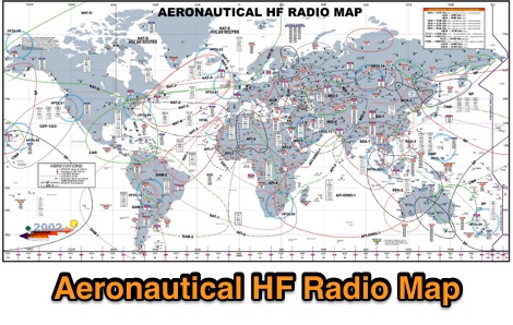 A worldwide map, dated 2002, visually presents aeronautical service frequency allocations across the **HF bands**. This resource details specific frequencies and their designated uses within the aviation sector, providing a geographical context for air traffic control, air-to-air, and air-to-ground communications. It serves as a reference for understanding the structured use of the radio spectrum by aircraft and ground stations globally, particularly for those interested in **radio scanning** or monitoring aviation communications. The map's utility extends to identifying regions and specific frequency ranges where aeronautical activity is concentrated, offering insights into international aviation communication protocols. While dated 2002, it provides a historical snapshot of spectrum management, allowing for comparisons with current allocations and practices. This visual aid assists in pinpointing potential listening targets for scanner operators and those studying spectrum utilization.
 -
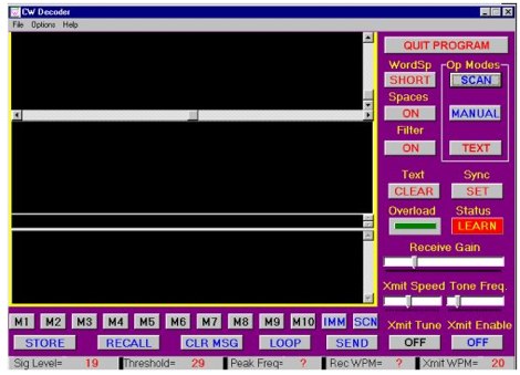 The CW Decoder program facilitates copying Morse code with a computer, displaying decoded CW as text, and generating a sidetone. It incorporates a spectrum display of the audio, allowing operators to select a specific audio frequency for decoding via a sliding cursor. This utility also enables keyboard-based transmitter keying, supporting full CW break-in operation for efficient QSO management. Developed by WD6CNF, the software is a Windows-compatible application designed to assist amateur radio operators in their CW activities. Its features cater to both decoding received signals and transmitting via keyboard input, streamlining the CW operating experience. Functionality includes real-time audio analysis and signal processing, providing a visual representation of the CW signal. The program's integrated keying capability offers a direct interface for transmitting, enhancing its utility as a comprehensive CW station tool.
 -
 Over 75 years of engineering expertise underpins Bird Electronic's offerings in RF power measurement, critical for maintaining peak performance in amateur radio stations and professional communication systems. The company specializes in a range of test equipment, including wattmeters, SWR meters, and antenna analyzers, essential for optimizing antenna systems and ensuring efficient power transfer. Their product line extends to various RF components such as filters, cables, and connectors, all designed to meet stringent technical specifications for reliability and accuracy across diverse frequency bands. Bird Electronic's instruments, like the _Bird 43_ Thruline Wattmeter, are widely recognized for their robust construction and precise measurement capabilities, providing hams with confidence in their station's operational parameters. These tools enable accurate assessment of forward and reflected power, SWR, and modulation characteristics, which are vital for troubleshooting and maximizing radiated power. The company's commitment to innovation ensures that its products remain relevant for modern RF challenges, from HF through microwave applications, supporting both traditional analog and advanced digital modes.
 -
 Details a practical QRP wattmeter construction, leveraging a simplified SWR meter design by JA6HIC. The project focuses on a forward-only power measurement circuit, providing a functional instrument for RF power levels from milliwatts up to 5 watts. It maintains a 50-ohm input and output impedance, suitable for typical QRP transceivers and antenna systems. The resource includes the schematic for the "VSW" (Very Simple Wattmeter) and outlines a six-step alignment procedure. This calibration process involves using a known RF source up to 5W, setting full-scale deflection, and marking power increments. It also addresses minimizing frequency effects on readings with a 100pF trimmer capacitor, noting that measurement error is highest at the lower end of the scale. Construction notes mention using a piece of RG-213 coaxial cable for the inductance and coupler, with the wattmeter assembled in early 2003. The author provides an example measurement showing 0.8W into a dummy load and 1W into a 3-element beam.
 -
 This PDF document, authored by KT4QW in October 2004, details the construction and modeling of a dual-band, horizontally polarized hanging rectangular loop antenna for **10 and 17 meters**. The design, adapted from *The ARRL Handbook*, utilizes _NEC4WIN95_ software for scaling and optimization, targeting a 50 ohm feedpoint impedance. The resource includes a bill of materials, step-by-step construction instructions, and a discussion of the antenna's radiation characteristics. It presents NEC-generated elevation and azimuth patterns, comparing the loop's performance to a half-wave horizontal dipole at the same height and frequency. The 17-meter element is centered at 18.140 MHz for low SWR across the phone band, while the 10-meter element is centered at 28.500 MHz. Construction involves 14-gauge stranded copper wire and Schedule 40 PVC spreaders, with the total wire length calculated by the formula: Length in feet = 1005/MHz. The feedpoint impedance can be adjusted by modifying the rectangular aspect ratio. The document specifies hoisting the antenna to at least a half-wave above ground for testing. It notes that a balun was tested and found to have no measurable effect on SWR or radiation characteristics. A 2-meter scale model is presented to illustrate the physical design, and a "rotator" string is incorporated for directional adjustment up to 90 degrees.
 -
 PA3FWM's software defined radio (SDR) page documents his extensive hardware and software development efforts between 2004 and 2009. Initial experiments utilized a direct conversion receiver with 90-degree phase difference, feeding a PC soundcard at 48 kHz sample rate, covering 24 kHz of spectrum around a 7080.5 kHz local oscillator. This setup, similar to AC50G's QEX 2002 article, allowed for basic I/Q signal processing to distinguish signals above and below the LO frequency. Limitations included fixed crystal frequencies, 16-bit dynamic range, and narrow bandwidth. Subsequent hardware iterations aimed for enhanced performance, incorporating external 24-bit ADCs with 192 kHz sample rates, connected via 10 Mbit/s Ethernet. A **MC145170-based PLL** and programmable octave divider provided a 58 kHz to 30 MHz tuning range. The **Tayloe mixer** was employed, with differential outputs feeding a PCM1804 ADC. An ATmega32 microcontroller handled serial data conversion to Ethernet frames, though without CRC calculation due to processing constraints. Later designs integrated AD7760 2.5 Msamples/second ADCs and a Xilinx Spartan-3 FPGA, enabling direct reception of 0-1 MHz spectrum and eventually 2.5 MHz bandwidth across the shortwave spectrum. Software was refactored to use an initial 8192 non-windowed FFT for efficient high-bandwidth processing. The project culminated in a two-way QSO on 21 MHz using the developed hardware and software, demonstrating transmit capabilities with a D/A converter. The system exhibited a 2.5 MHz wide spectrum display and a zoomed 19 kHz display, capturing signals like ionospheric chirp sounders and RTTY contest activity. Challenges included noise leakage from digital circuitry and cooling for high-power dissipation components.
 -
 This is a resonant, half-wave, vertical antenna. It takes up little space in the back yard, was designed for operation on a single frequency 80 meter PSK net, and is reasonably inexpensive to construct by Chuck Hines, K6QKL
 -
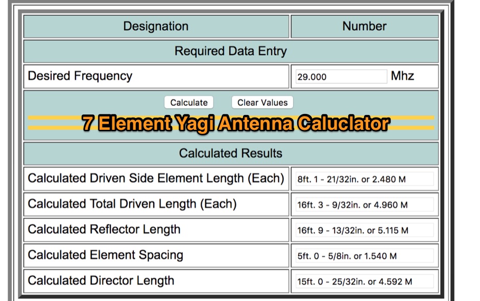 Online javascript antenna calculator designed to give the critical information of a particular beam antenna, in this case a seven element Yagi, for the frequency chosen.
 -
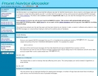 Approximately 400 kHz is the primary frequency for Navtex broadcasts, a crucial maritime safety information system. This legacy software, _Frisnit Navtex Decoder_ version 2.1.5, provides a means to decode these messages directly from an amateur radio receiver's audio output, fed into a PC's microphone input. It operates by processing the audio stream, extracting the FSK (Frequency Shift Keying) data, and presenting the decoded text on a Windows platform. Despite being unsupported and no longer under active development, the application remains functional across a wide range of Microsoft operating systems, from _Windows 95_ through _Windows 11_. Its utility lies in offering a straightforward, no-cost solution for hams and SWLs interested in monitoring Navtex transmissions without specialized hardware. The software's design focuses on simplicity, allowing users to quickly set up and begin decoding maritime weather forecasts, navigation warnings, and other safety-critical information. It leverages the PC's sound card, making it accessible with minimal additional equipment beyond a receiver capable of tuning to the Navtex frequencies.
 -
 Calculates precise dimensions for **Moxon rectangle** HF antennas, enabling hams to design antennas by inputting desired resonant frequency and wire diameter. This web-based tool, version 0.5, is a PHP front-end developed by W4/VP9KF, based on a public domain BASIC program originally authored by L. B. Cebik, W4RNL. It generates critical measurements for the driven element and reflector, ensuring proper spacing and element lengths for optimal performance. User feedback confirms the calculator's accuracy, with one user reporting resonance within 50 Hz of the design frequency for an 18 MHz antenna, eliminating the need for SWR adjustments. This contrasts with other online tools that resulted in significant frequency discrepancies. The tool's precision facilitates building **directional antennas** for specific bands, contributing to effective DXing and contesting operations.
 -
 The purpose of the APRS-Beacon is to provide simple APRS-compatible position beacons for up to three Objects. It is designed to 'stand alone' and does not monitor other traffic on the frequency. It can use a single-port TNC (in 'native' mode), a single- or dual-port TNC in Kiss mode or the AGW Packet Engine in order to transmit on up to four radio ports.(When running with AGWPE, APRS-Beacon will also work with Windows 2000)