Search results
Query: wave
Links: 988 | Categories: 55
Categories
- Antennas > End-Fed > End Fed Half Wave Antenna
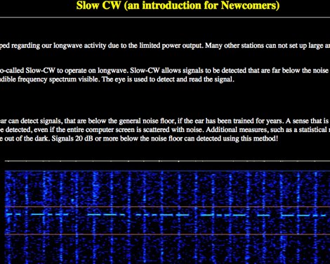
- Operating Modes > Longwave
- Antennas > Longwave
- Manufacturers > Microwave
- Shopping and Services > Microwave
- Operating Modes > Microwave
- Antennas > Microwave
- Shopping and Services > Antennas > Microwave Antenna
- Manufacturers > Antennas > VHF UHF Microwave > Microwave antennas
- Technical Reference > Mircrowave
- Software > Shortwave
- Antennas > Shortwave
- Shortwave Radio
- Manufacturers > Antennas > VHF UHF Microwave
- Technical Reference > Standing Wave Ratio
- DX Resources > Beacons > 10 GHz Beacons
- Antennas > 40M > 40 meter Loop Antennas
- Operating Modes > Aircraft scatter
- Manufacturers > Antennas
- Radio Scanning > Regional > Australia
- Shortwave Radio > BCL Resources
- DX Resources > Beacons
- Shortwave Radio > Beginner's guides
- Shortwave Radio > Broadcasters
- Manufacturers > Broadcasting Equipment
- Shortwave Radio > Clubs
- Manufacturers > Antennas > VHF UHF Microwave > Discone Antennas
- Antennas > End-Fed
- Manufacturers > Antennas > VHF UHF Microwave > Ground Plane Antennas
- Antennas > Horn
-

-
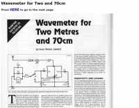 G8ACC article project for a 144 & 430 MHz wavemeter
 -
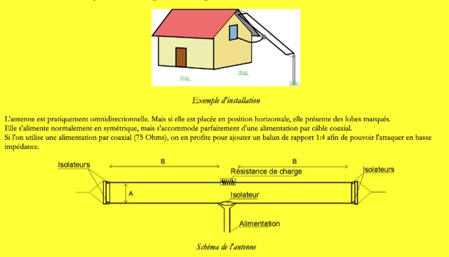 W3HH wide-band wire antenna Article in French. The W3HH antenna, also known as the Terminated Folded Dipole (T2FD), is a compact, broadband antenna for amateur radio. It operates at an angle of 20 to 40 degrees and covers frequencies from 3 to 30 MHz. The antenna features a total length of one-third of the wavelength at its lowest frequency and is fed using a 1:4 BALUN transformer for impedance matching. A termination resistor around 390 Ω optimizes performance, making it suitable for various amateur radio applications while being easy to construct and install.
 -
 Experimental Longwave Transmissions from Tower Hill wayland Massachusetts Operator Name Warren, Ham Call K2ORS, Frequency: 137.7796 KHz
 -
 This circuit is very simple and has a fantastic range of potential uses.
 -
 The article, "Using 75 Ohm CATV Coaxial Cable," details methods for employing readily available 75-ohm CATV hardline in standard 50-ohm amateur radio setups. It addresses the inherent impedance mismatch and practical considerations, such as connector compatibility, for hams seeking cost-effective, low-loss feedline solutions. The resource specifically contrasts common 50-ohm cables like RG-8, RG213, and _LMR-400_ with 75-ohm hardline, highlighting the latter's lower loss characteristics, particularly at VHF and UHF frequencies. It explores two primary approaches to manage the impedance difference: direct connection with an acceptable SWR compromise and precise impedance transformation. The direct connection method acknowledges that a perfect 1:1 SWR is not always critical, especially when using low-loss coax. For impedance transformation, the article explains the use of half-wavelength sections of coax to reflect the antenna's 50-ohm impedance back to the transmitter, noting its single-frequency effectiveness. It also briefly mentions transformer designs using toroid cores and a technique involving two 1/12 wavelength sections of feedline for broader bandwidth. The content further clarifies the concept of _velocity factor_ for calculating electrical versus physical cable lengths, providing a generic formula for precise length determination. It notes that while half-wave matching is practical for 10 meters and above, it can result in excessively long runs for lower bands like 160 meters, potentially adding **250 feet** of cable. The article also mentions achieving a usable bandwidth of 28.000 MHz up to at least **28.8 MHz** on 10 meters with specific transformation techniques.
 -
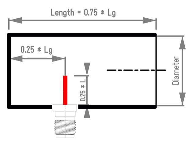 Aka Circular Waveguide Antenna. This online antenna calculator let you plan your cantenna for the desired frequency of operation, giving the Can diameter you have available.
 -
 A synthesized 2.3 GHz Amateur Television (ATV) transmitter design, conceived by Ian G6TVJ, is presented, targeting broadcast-quality video performance on the 13cm band and extending up to 2.6 GHz. The core of the design utilizes a commercial Z-comm Voltage Controlled Oscillator (VCO) that tunes from 2.2-2.7 GHz, providing a +10 dBm output and simplifying RF alignment. This VCO's stability, originally intended for narrowband applications, readily accepts high-frequency video modulation, contributing to the transmitter's robust performance. The exciter stage, incorporating a Mini Circuits VNA 25 MMIC amplifier, boosts the signal to +16dBm, while a Plessey SP4982 prescaler divides the output frequency for the synthesizer. The synthesizer employs a Motorola MC145151 CMOS parallel IC, favored over the common Plessey SP5060 for its superior video modulation characteristics and ease of programming without microprocessors. This choice addresses issues like LF tilt and distorted field syncs often seen with SP5060 designs, particularly when operating through repeaters or over long distances. The MC145151 divides the signal further, enabling precise frequency stepping, with programming handled by EPROMs for channel selection and LED display. The loop filter network, critical for video integrity, was developed through experimentation to prevent the PLL from reacting to video modulation, ensuring a clean transmitted picture. The transmitter incorporates a Down East Microwave commercial power amplifier module, delivering approximately 1.6W output, driven by the exciter through a 3dB attenuator. Construction involves surface-mount SHF components on micro-strip lines etched onto double-sided fiberglass board, housed within a tinplate box. The design boasts no AC coupling in the video path, preserving low-frequency response, a common failing in other ATV transmitters. Performance tests with a 50Hz square wave revealed no LF distortion, and a calibrated "Pulse & Bar" signal showed a near 100% HF response, demonstrating its capability for high-quality ATV transmissions.
 -
 A 102-inch vertical whip, commonly a CB antenna, forms the core of this low-profile 10-meter antenna design, optimized for the 28 MHz band. The construction details specify three 8-foot radials made from scrap wire, connected to a common point. This simple yet effective setup is designed for ease of construction and deployment, making it accessible for operators with limited space or materials. The design emphasizes using readily available components, including PVC pipe for the mast and a SO-239 connector for the feedline, ensuring a straightforward build process for a resonant quarter-wave vertical. Field results indicate that this antenna provides good performance for local and DX contacts on 10 meters, despite its compact footprint. The author, N8WRL, shares practical insights into its construction and tuning, highlighting its suitability for temporary or permanent installations where a full-sized antenna might be impractical. Comparisons to more complex designs suggest that this low-profile vertical offers a respectable signal-to-noise ratio and effective radiated power for its size, proving that simple designs can yield satisfying on-air results.
 -
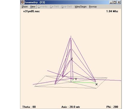 Design for a quarter wave vertical antenna, for the top band in use at V31YN
 -
 This web article details the construction of a 4-meter band coaxial dipole antenna, designed for operation between **70.000 MHz and 70.500 MHz**. The resource provides a bill of materials and step-by-step assembly instructions for a half-wave dipole constructed from _RG-58_ coaxial cable. The design specifies a direct 50 ohm feedpoint impedance, eliminating the need for an external matching network. Construction photographs illustrate the stripping and soldering processes for the coaxial cable elements, ensuring proper electrical connection and physical integrity. The article includes specific dimensions for the radiating elements, derived from calculations for the 70 MHz band. The project outlines the physical dimensions required for resonance at 70 MHz, with the outer braid forming one half and the inner conductor forming the other. The feedline connection is directly to the coaxial dipole's center, maintaining a 50 ohm characteristic impedance. While the article does not present SWR plots or VNA sweeps, it focuses on the mechanical construction and dimensional accuracy for achieving a functional 4-meter dipole. The design is intended for fixed station use, with no specific mention of polarization or height above ground, but implies a standard horizontal orientation for dipole operation. DXZone Focus: Web Article | 4m Coaxial Dipole | Construction Guide | 50 ohm Feed
 -
 Broadband instruments, R and microwave components and filters, field analyzers, spectrum analyzers
 -
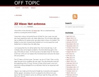 Setting up a ZZ Wave antenna, a dual band loop antenna covering 80 and 40 meters.
 -
 Sw tool to design point-to-point multi-hop microwave links and networks, 400MHz to 58 GHz. Site/Hop Configuration; Customized Antenna & Radio Equipment Libraries; Link Budget; Path Profile Analysis ,clearance, reflections; import path profiles from SRTM maps, free download.
 -
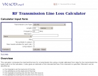 1.5 dB of matched line loss can be calculated for a given transmission line using this online tool, which employs a model calibrated from empirical data. The calculator allows radio amateurs to input specific transmission line types, such as _RG-8_ or _RG-58_, and then determine the expected signal attenuation. This is crucial for optimizing antenna system efficiency and understanding power delivery to the radiating element, especially for HF and VHF operations where feedline losses can significantly impact performance. Beyond matched loss, the calculator also provides an estimate for mismatched loss if the Standing Wave Ratio (SWR) is specified. This feature helps operators quantify the additional power loss due to impedance discontinuities between the transceiver, feedline, and antenna, which is a common concern in amateur radio installations. Accurate loss calculations are vital for effective station design and for predicting actual radiated power. The tool's utility extends to various operating scenarios, from fixed station setups to portable deployments, aiding in the selection of appropriate feedline lengths and types to minimize signal degradation. Understanding these losses is a fundamental aspect of maximizing the effectiveness of any amateur radio antenna system.
 -
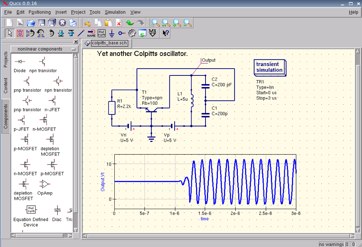 RF/Microwave Simulator for Puppy Linux by WN2A
 -
 Storm Products Company provides high-value, interconnect products, subsystems, and services to electronics, communications, and instrumentation markets worldwide. Products include Electronic and Microwave cable assemblies, components, and test products.
 -
 Multi-frequency radio interferometers
 -
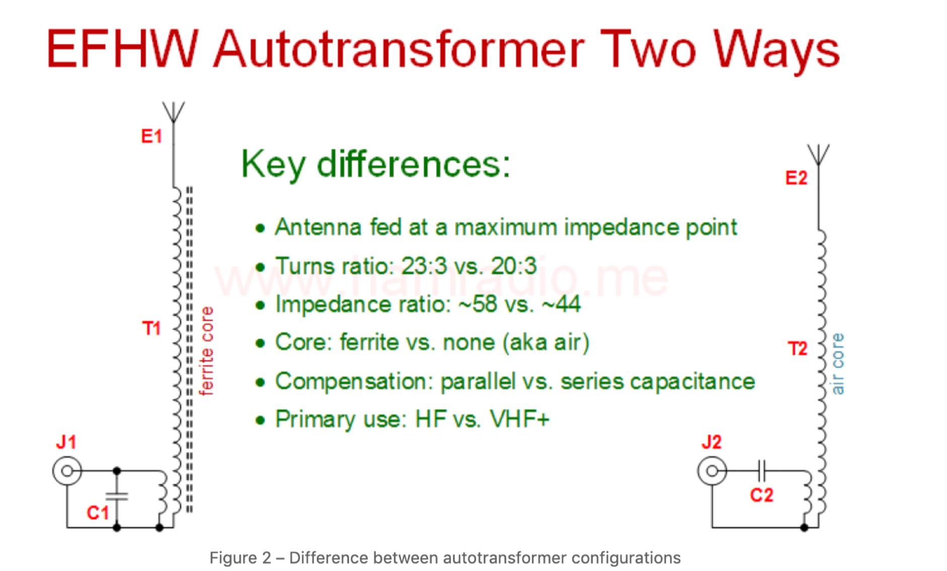 Two different ways to create autotransformer for end fed half wave wire antennas, by using ferrite or air core.
 -
 Amplifiers, filters, attenuators, mixers, PLL, switches and frequency dividers, signal generators, power detectors, transimpedance amplifiers, variable gain amplifiers and more
 -
-
 European relay station broadcasting every weekend on short-wave to all of Europe, Northern Africa and the Middle East on 13840 kHz.
 -
 Dealer of electronic test equipment dealers since 1977 equipment manufactured by Tektronix, Hewlett Packard, General Radio, Dranetz, Bird, Fluke, ENI, ESI, Wavetek, Narda, Keithley, Weinschel, Microlab/FXR, Systron Donner, Kepco, Lambda
 -
-
 News, frequency guides and programme information, on shortwave and other international media.
 -
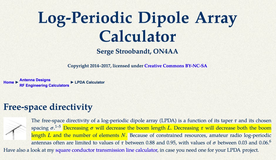 This LPDA calculator is based on the design procedure as described by L. B. Cebik, W4RNL (SK) in the 21st edition of The ARRL Antenna Handbook.
 -

-
 Maxdao: offer you 7/16, N coaxial connectors, jumper cables, feeder clamps and grouding kits, surge arresters & brackets, wall entries and microwave components used in base tower, power dividers, couplers
 -
-
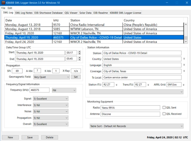 A shortwave radio listeners log book runs on Windows and MacOS Catalina and above. The KB6IBB SWL Logger is a program designed for the shortwave radio listener. It offers shortwave specific logging of stations, with most tasks handled automatically. The program also incorporates the use of EiBi shortwave database for logging and looking up various known shortwave stations world wide.
 -
 OK0EU is short-wave QRP beacon set up by the OK QRP Club and supported by the Institute of Atmospheric Physics of the Academy of Sciences of the Czech Republic (UFA).
 -
 A collection of ad Hoc empirical comments on VHF radio waves propagation by Pete Heins N6ZE
 -
 Amateur projects to investigate radiowave propagation - G3PLX's chirp project, ionosonde database, and more
 -
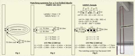 Matching with a half wave or wuarter wave coaxial cable is pretty well known, but an existing 1961 system to do that with two one-twelfth-wavelength transmission lines.
 -
 An overview of the basics of the horn antenna used in RF microwave applications.
 -
 Demonstrates the complete design and development process for a **Low Noise Microwave Amplifier** (LNA), beginning with conceptual design and progressing through prototyping. The tutorial series covers the initial stages of a single-ended first gain stage, focusing on critical parameters such as noise figure, gain, and stability. It systematically details the theoretical underpinnings and practical considerations for achieving optimal performance in microwave frequency applications. This resource provides a structured approach to LNA construction, enabling radio amateurs and RF engineers to understand the iterative steps involved in realizing high-performance receive-side amplification. It offers insights into component selection, impedance matching networks, and the measurement techniques required to validate design specifications, particularly for **microwave** band operation where noise performance is paramount.
 -
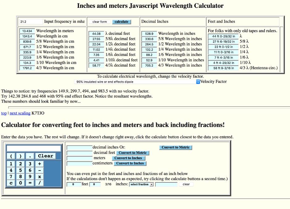 Inches and meters Javascript Wavelength Calculator allow to input a frequency in MHz and calculate wavelenght in several units considering also fractions of wavelenght and the velocity factor. Includes an usefull inch to meter converter
 -
 Summary, tutorial about the basics of what is a waveguide and the basic waveguide theory.
 -
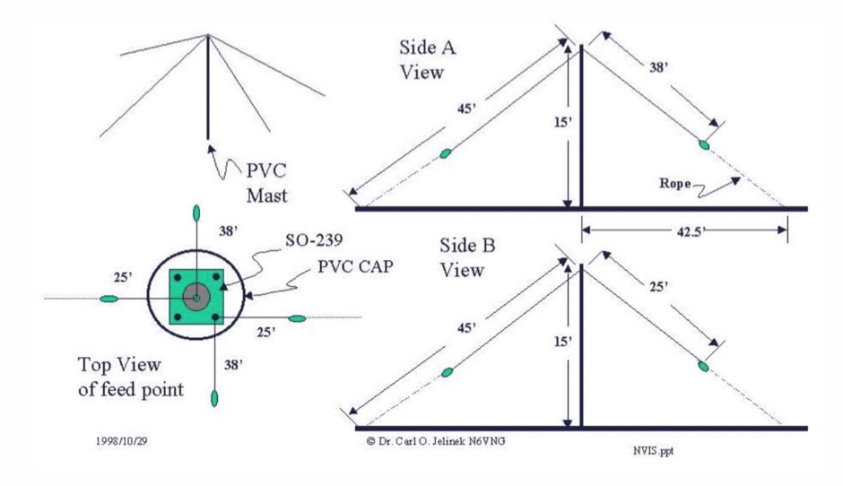 Introduction to NVIS antenna and NVIS propagation. A simple NVIS antenna can be constructed as shown in this article
 -
 International Public Access Radio via IRRS Shortwave and Internet Radio NEXUS via MP3 streaming audio
 -
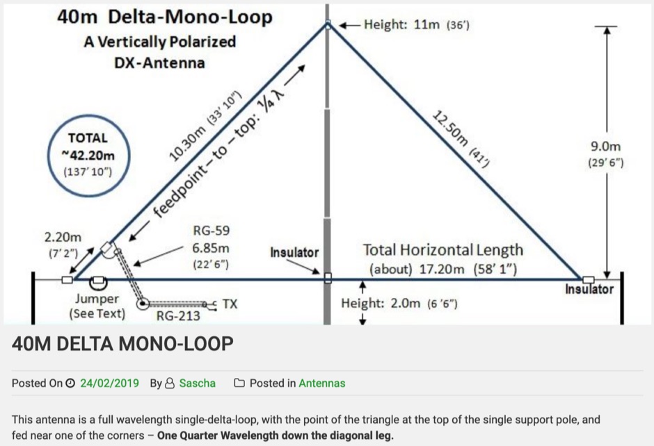 A monoband delta loop antenna for the 7 MHz. This vertically polarized DX Antenna is a full wavelength sngle side antenna and has a total length of 42.3 meters (137,1 inch) Can be easily setup with a flag pole or fishing pole as center top mast. For optimal performance lower side should be at 2 meter above the ground. This antenna offers a low radiation angle and 1 DB Gain.
 -
 The Shortwave Radio Audio Archive is a collection of shortwave radio recordings in both the form of a podcast and blog with embedded audio. The collection grows every day and includes both historic and modern day shortwave radio audio recordings
 -
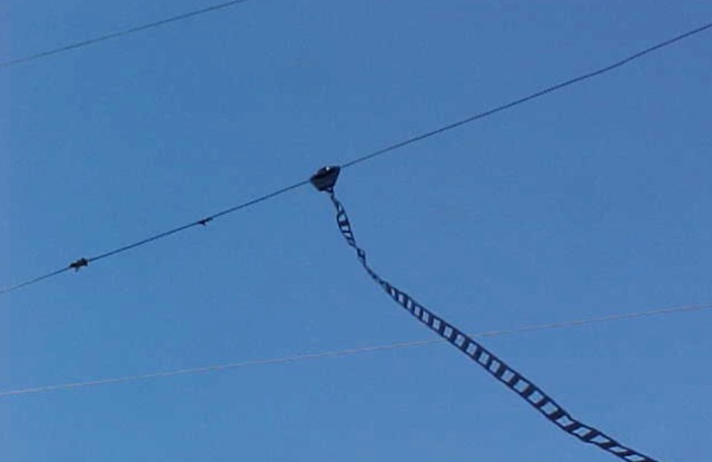 Complete collection of the four main parts of this excellet research on modelling and designing half wave dipole antennas for 40 meters band, covering all aspects beginning from full wave length antennas, to shortened, loaded and reshaped dipoles
 -
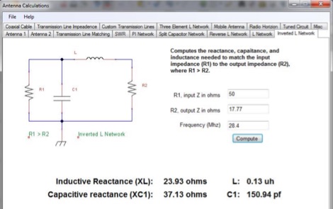 The program consists of tabbed pages for various antenna and transmission line calculation. You can compute the values for an inverted L network that will allow you to match the 50 ohm output of the radio, or you can compute the necessary length in the units of choice for a 5/8 wave vertical for 10 meter band.
 -
-
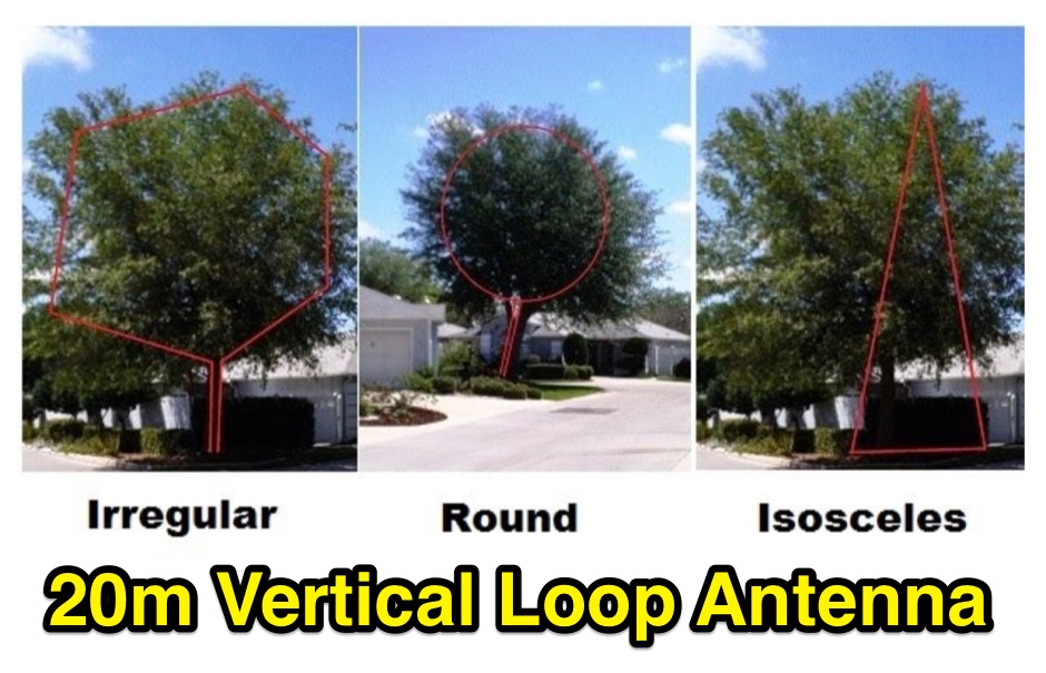 Consider installing a stealth vertical loop antenna if you live in a place with no antenna restrictions. Full wave loop wire antennas allow you to be on the air without installing evidente external aerials.
 -
 Naptech buys and sells quality test equipment from hp, tektronix, including spectrum analyzers & peripherals, oscilloscope, frequency counters timers, signal generators, multimeters & voltmeters, RF & power meters, microwave amplifiers
 -
 Signal generatos, oscillators, direct and indirect synthesizers, exciters custom oscillators
 -
 About experiments and measurements on loading coils using net standing wave current
 -