Search results
Query: transmission
Links: 280 | Categories: 15
Categories
- DX Resources > Beacons > 10 GHz Beacons
- Software > ACARS
- Software > Audio Recorders
- Software > Digital Amateur Television
- Software > DX Cluster
- Operating Modes > ESSB
- Antennas > Feed Lines
- Operating Modes > NBEMS
- Radio Scanning
- Software > RF Design
- Operating Modes > Robust Packet
- Technical Reference > Standing Wave Ratio
- Operating Modes > System Fusion
- Antennas > Theory
- Software > Voice Keyer
-
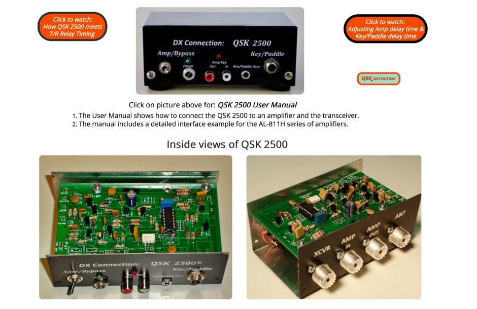 QSK 2500 enhances HF amplifiers by enabling full break-in (_QSK_) operation, allowing for seamless communication during CW transmissions. This device supports **all** HF transceivers that are QSK-compatible, ensuring versatility across various setups. The QSK 2500 facilitates quick switching between transmit and receive modes, which is crucial for effective DXing and contesting. With its straightforward installation, operators can achieve **improved** responsiveness in their communications without the need for extensive modifications to their existing amplifiers. This project is particularly beneficial for those engaged in high-speed CW operations, where timing is critical.
 -
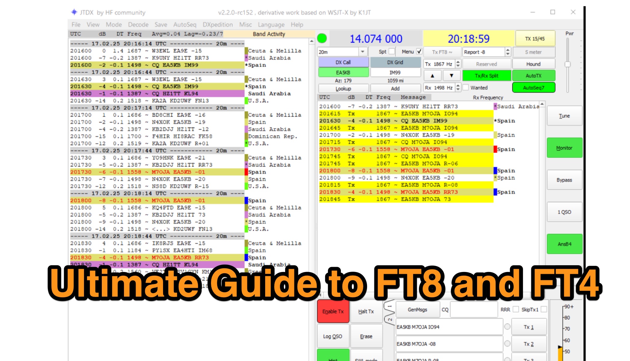 Learn all about FT8 and FT4 digital modes in ham radio. Discover how to configure software to use these powerful modes for making contacts even in poor conditions. Find out how to hunt for awards and view instant statistics of your transmissions. Explore the benefits of using digital modes such as FT8 and FT4 for enhancing your ham radio experience.
 -
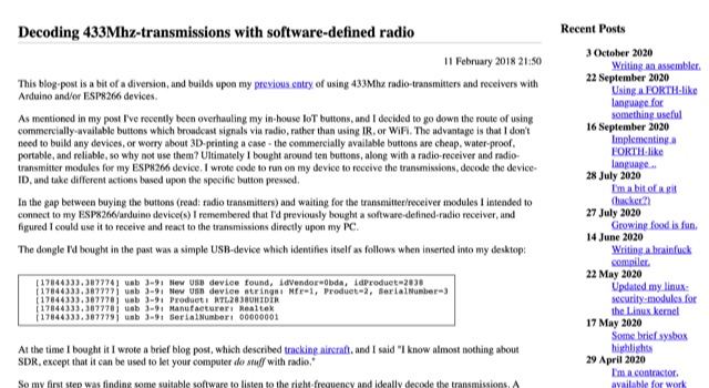 Decoding 433MHz-transmissions with software-defined radio.
 -
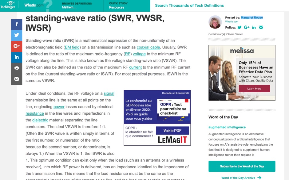 Article about Standing-wave ratio (SWR) defined as a mathematical expression of the non-uniformity of an electromagnetic field on a transmission line. SWR is the ratio of the maximum radio-frequency (RF) voltage to the minimum RF voltage along the line.
 -
 You can bend the wires in a half-wave dipole so that it takes up less space, with minimal loss of efficiency.It is advisable to get the ends of the antenna as high as possible, especially if children and animals are kept in the area around the antenna, as there are very high tensions on the ends of the antenna during transmission! In Norwegian
 -
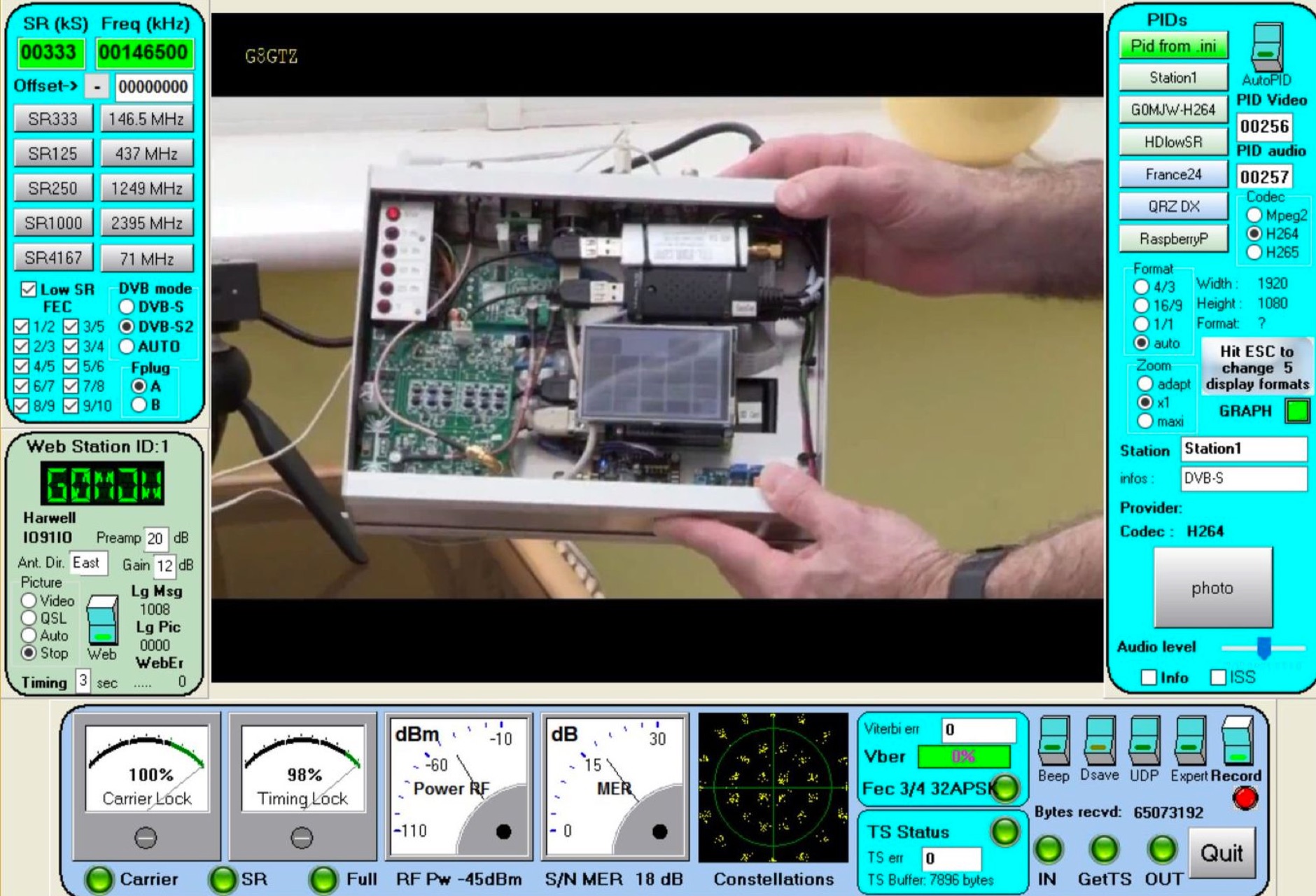 The MiniTioune receiver project, developed by Jean-Pierre F6DZP, consists of the home constructed MiniTiouner hardware which interfaces via a standard USB 2.0 port to a Windows PC running the MiniTioune software. It can be used to receive satellite broadcasts transmissions making it ideal for use on Q-oscar 100 Es hail-2 without any external frequency converters.
 -
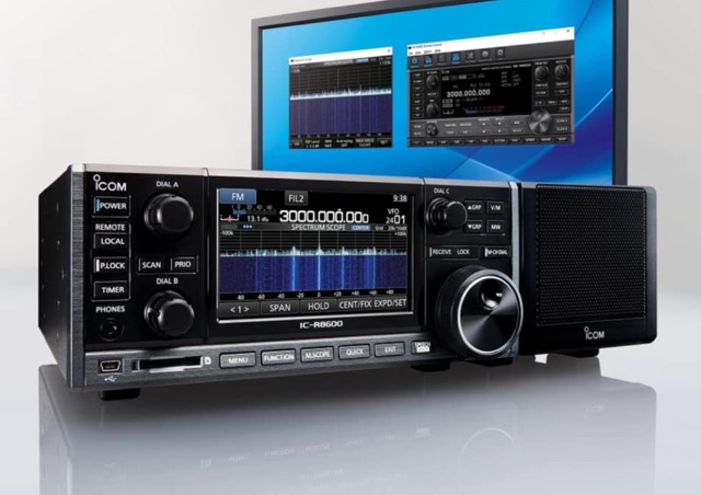 Tuning into the airwaves for new and interesting transmissions has fascinated enthusiasts since the very earliest days of radio. As a result of advances in computer and radio technology, the equipment packed radio rooms of the past are now replaced by scanning receivers sometimes just the size of a mobile phone. What can radio receivers/scanners pick up? What types of radio receivers/scanners are there? What can and cannot be monitored legally? Best practice when using a radio receiver/scanner
 -
 The video showcases the setup of a 300 MHz oscillator, a 100W radiofrequency amplifier, and a dipole antenna for transmitting radio waves, leading to the fluorescence of a nearby light bulb. It demonstrates the presence of standing waves on the dipole antenna and how intensity varies along its length. Additionally, the usage of a copper pipe as a receiving antenna is explored, showing changes in intensity depending on alignment and proximity to the transmitter. Finally, a B field antenna sensitive to magnetic fields is introduced, revealing brightness variations in different orientations. The video offers insightful observations on radio wave transmission and reception phenomena.
 -
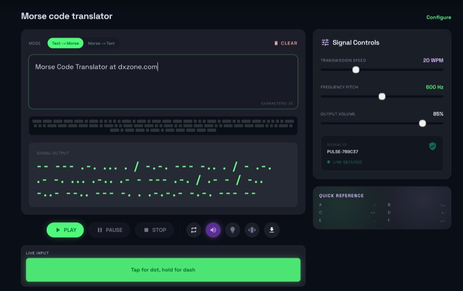 The morsecodeworld.org web application provides an online Morse code decoder and encoder, facilitating real-time conversion between text and International Morse code. It supports adjustable transmission speed (Words Per Minute), sidetone frequency pitch (Hz), and output volume, allowing users to customize their learning and practice environment. The tool includes a quick reference chart for the Morse alphabet and focuses exclusively on International Morse, aligning with contemporary amateur radio licensing and on-air practices, distinguishing it from historical American Morse code. This web-based utility enables users to type text for encoding into Morse audio or paste Morse code for decoding into plain text, offering immediate feedback on timing and character spacing. It supports both visual and auditory learning by providing adjustable parameters for speed and tone. The platform is designed for self-assessment, encouraging users to practice copying and sending, and to identify and correct common errors in character recognition and timing.
 -
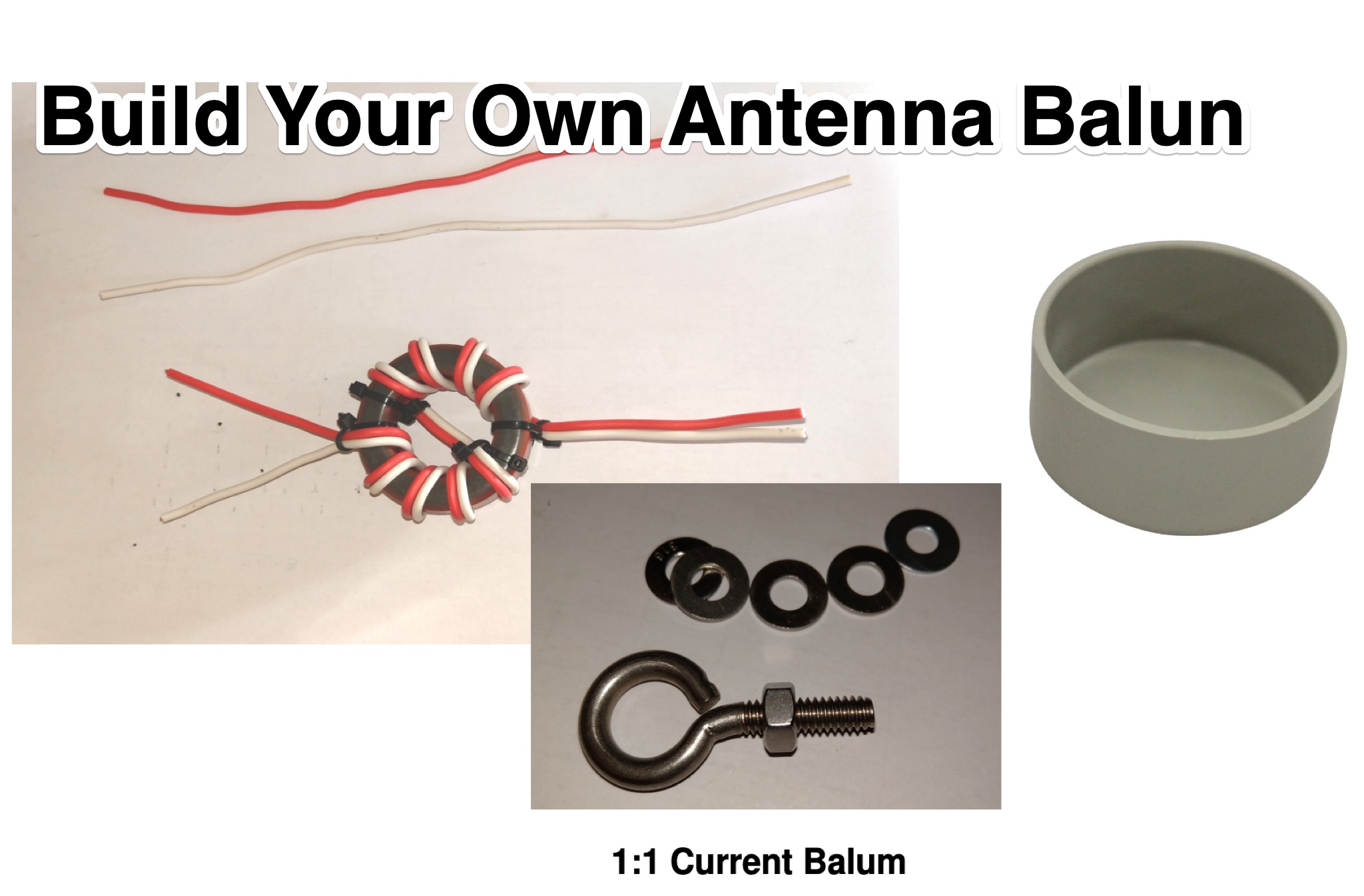 This PDF guide provides step-by-step instructions on how to build a Bunnings Balun for your ham radio antenna. A balun is essential for matching the impedance between your antenna and radio, improving signal transmission. The guide is perfect for hams looking to enhance their radio setup on a budget. Follow the detailed instructions to create your own balun using easily accessible materials from Bunnings or any hardware store.
 -
 The AN-55A ATV Handbook PDF is a document providing information and guidance on Amateur Television (ATV) for hams interested in setting up and operating ATV systems. The handbook covers topics such as equipment, setup, operating procedures, and technical details related to ATV transmissions. It is a useful resource for hams looking to explore the world of ATV and engage in video communications through amateur radio. The content aims to educate and inform hams about the intricacies of ATV technology and operation.
 -
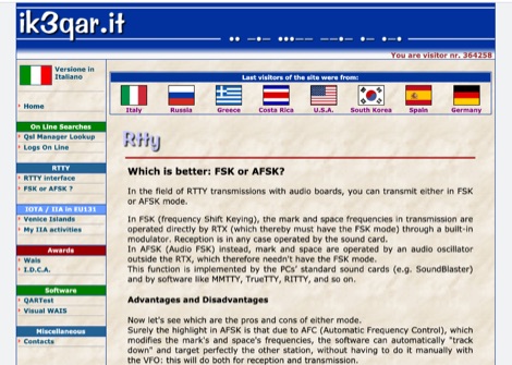 In the field of RTTY transmissions with audio boards, you can transmit either in FSK or AFSK mode. Which is better: FSK or AFSK? Advantages and Disadvantages of both methods
 -
 Learn about the practical design and construction of Yagi antennas for ham radio operators. This post explores the benefits of Yagi antennas in receiving and transmitting RF signals, concentrating signal energy in one direction for long-distance communication. Discover the theory behind Yagi antennae, the importance of element size and spacing, and the resources available for sizing and construction. Whether you're interested in OTA television or amateur radio communication, understanding Yagi antenna design can enhance your signal reception and transmission capabilities.
 -
 Learn how to design and analyze a folded trifilar antenna for the 80-meter band. Based on a description from RAF antennas between 1940 and 1970, this article provides step-by-step guidance on modeling the antenna, calculating resonance frequency, adjusting dimensions, and verifying performance. Perfect for hams looking to improve their antenna setup for better transmission and reception on the 80M band.
 -
 Otto enhances WSJT-X, the popular weak-signal digital modes program for amateur radio. It automates tasks like managing QSOs, prioritizing DX stations, replying to specific calls, and optimizing band usage. Otto works with a modified WSJT-X version (v2.7.0) to add advanced features such as directed CQs, automatic logging, and multi-stream replies. Its intuitive modes streamline operations, while safety measures ensure controlled transmissions. Ideal for DX enthusiasts, Otto improves efficiency and focus, making weak-signal operations more engaging and productive.
 -
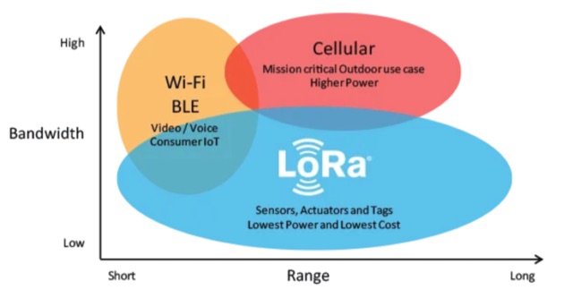 About LoRa, wireless communication technology designed to transmit data over long distances. LoRa provides a means for wireless data transmission over long distances with low power consumption. Practical applications of LoRa in amateur radio
 -
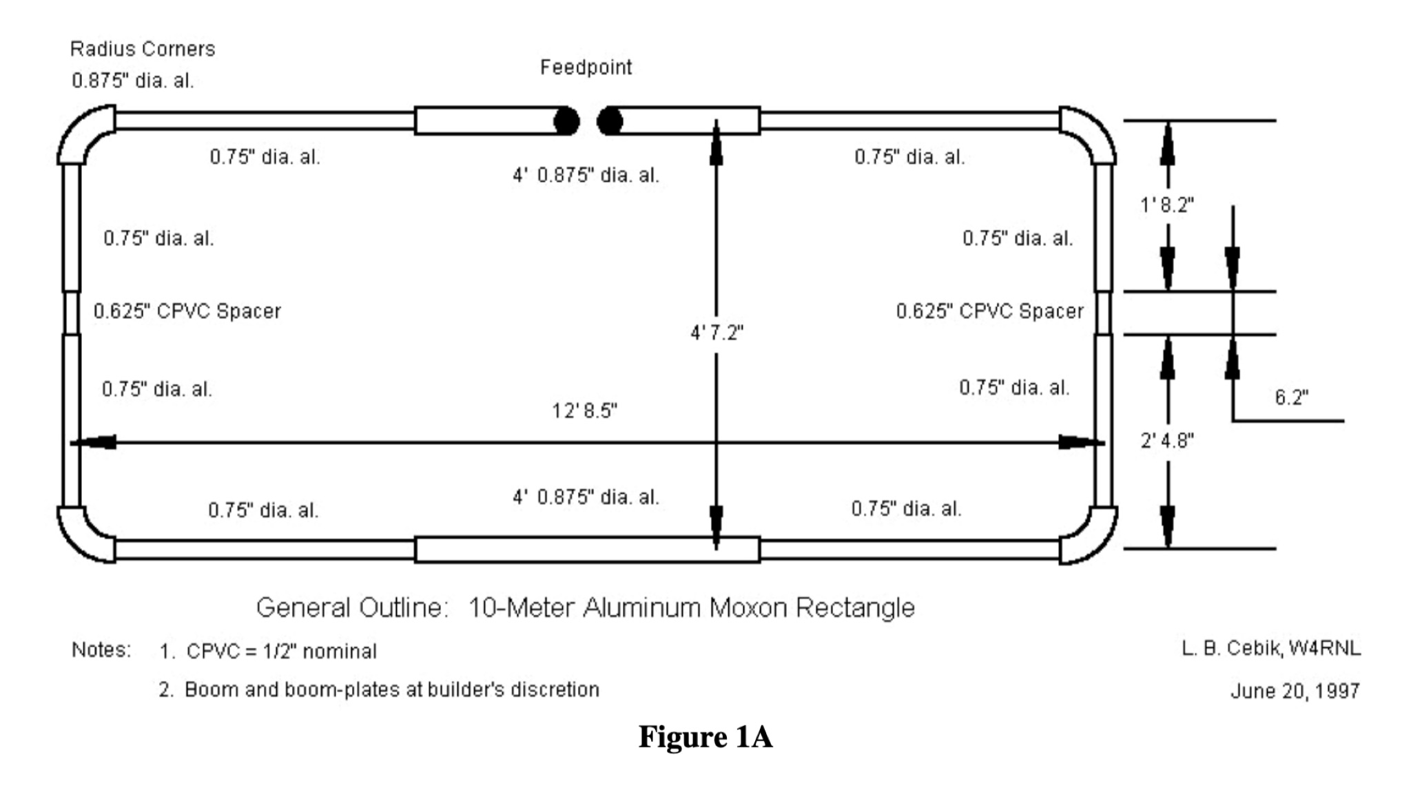 This PDF document provides a comprehensive guide on building and using the Moxon Rectangle antenna design for hams. It covers the construction, setup, and tuning of this directional antenna, offering practical advice and tips for amateur radio operators looking to improve their signal reception and transmission capabilities. The guide includes diagrams, measurements, and step-by-step instructions to help hams successfully implement the Moxon Rectangle design for their radio communication needs.
 -
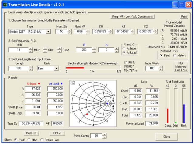 This utility program shows the impedance and reflection coefficient parameters (SWR, reflection coefficient magnitude Rho, or Return Loss RL in dB) at both ends of a transmission line and the details of power loss in the line. It includes built-in specifications for approximately 100 different line types. You can modify the specs to see how small changes affect the results or to specify custom lines. All program inputs may be changed directly or you can use spin buttons to make the changes.
 -
 This article describes the phases for the construction of a Yagi antenna. The calculations of the parameters are made using 4NEC2 software. This type of antenna is used for transmissions and receptions of electromagnetic waves. The project shown here refers to the frequency of 433.92 MHz.
 -
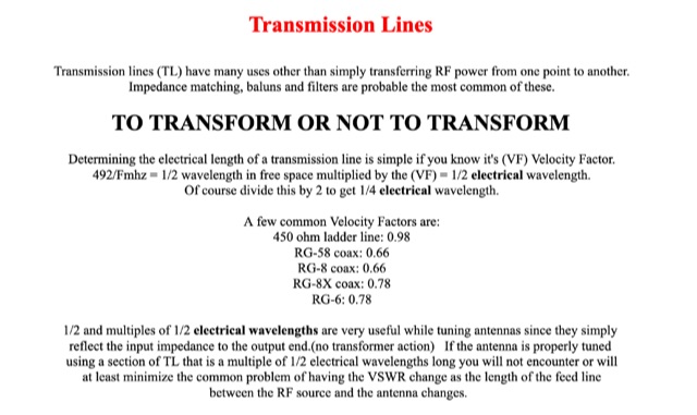 Transmission lines have many uses other than simply transferring RF power from one point to another. Impedance matching, baluns and filters are probable the most common of these.
 -
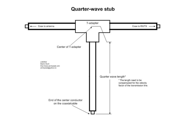 The Quarter-wave stub can be used for many purposes. If it is left with an open end it can be used as a notch filter to attenuate certain frequencies. A quarter wave length of a transmission line can also be used as an impedance transformer, to know more about the Quarter-wave impedance transformer
 -
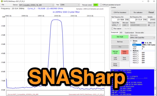 SNASharp is a free software application designed to work with scalar network analyzers compatible with NWT software from DL4JAL. It is used to measure and analyze the scattering parameters (S-parameters) of microwave devices. Provide several measurements and analysis tools including Smith chart, Polar plot, S-parameter tables, Transmission line calculator
 -
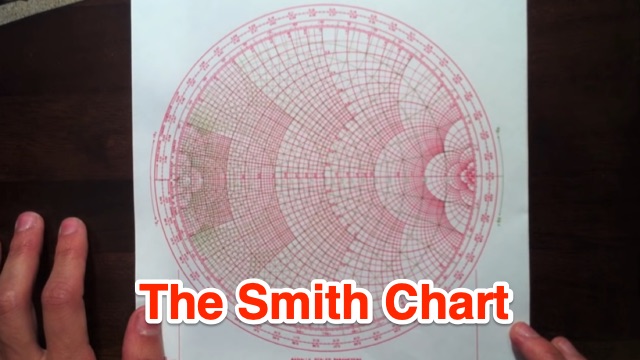 This tutorial introduces and explains Smith Charts, and then gives an introduction to impedance matching. Smith Chart is a tool to visualize the impedance of a transmission line and antenna system as a function of frequency.
 -
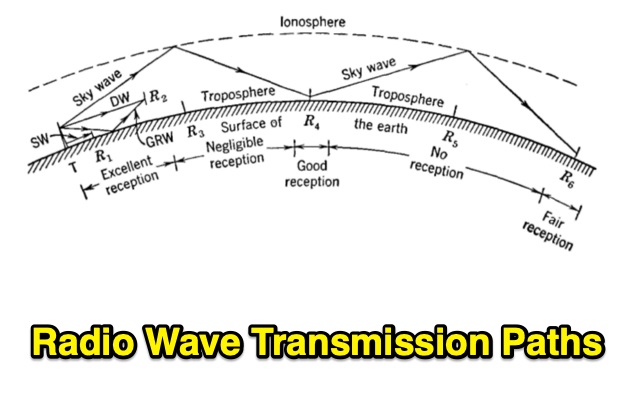 Radio transmission is affected by the presence of the earth. Also, the upper atmosphere of the earth is a rarefied, ionized, conducting region that influences transmission considerably. Undertanding Wave Diffraction, Wave Refraction and Absorption
 -
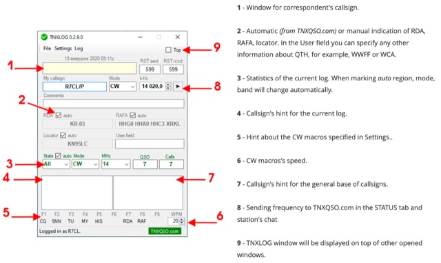 TNXLOG is a specialized logging application designed to complement the TNXQSO.com online service, focusing on real-time data exchange rather than serving as a standalone general-purpose logbook. The software facilitates the transmission of current **QSOs** to the TNXQSO.com server and simultaneously retrieves relevant geographical data such as RDA, Locator, and RAFA from the same server. It maintains real-time QSO statistics, providing operators with immediate feedback on their activity. Additionally, the application supports working with **CW macros** via a COM port, streamlining Morse code operations during contacts. This utility is specifically tailored for users of the TNXQSO.com service, enhancing their operational experience by automating data synchronization and providing instant access to location-specific information. Its design prioritizes integration with the online platform, making it a companion tool for those engaged in specific award programs or regional operating activities that benefit from real-time data exchange and statistics. The software's functionality is distinct from traditional logbook programs, emphasizing its role in a connected operating environment.
 -
 This DIY guide details constructing a 5-element Yagi antenna for VHF frequencies. Yagi antennas offer directional signal transmission/reception compared to omnidirectional ones. The guide covers material selection (aluminum, screws, etc.), design using software or formulas, and step-by-step assembly including cutting elements, drilling holes, and attaching the coaxial cable. While calculations are provided for a 146 MHz design, adjustments are necessary for different frequencies. Safety precautions and potential result variations are emphasized.
 -
 This page provides detailed instructions on refining an end-fed vertical dipole antenna for ham radio operators looking to improve their signal reception and transmission. The content offers practical tips and techniques for optimizing the performance of this specific type of antenna. The page is useful for hams who are interested in experimenting with different antenna designs and configurations to enhance their overall radio communication experience.
 -
 A data converter for the Tandy WM918 weather station. The Weather APRS data converter project aims to create an interface to interpret data from the popular Tandy WM918 weather station and format it for transmission over packet radio. The South East Radio Group in South Australia has established a network of these weather stations to provide amateurs with regularly updated weather data. However, the WM918's data output is not structured for APRS weather reporting. This project describes a solution using a PIC microcontroller to convert the WM918 data into APRS-compatible strings that can be sent as beacons or connected packets. The interface offers features like position/positionless data, connected/beacon modes, and metric/imperial units. The goal is to create an interconnected weather reporting system for amateur radio operators
 -
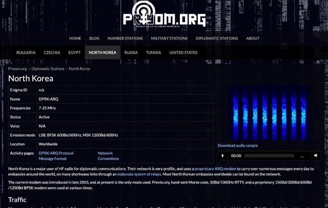 The resource details active HF radio networks maintained by foreign ministries for diplomatic communications, specifically listing operational schedules and frequencies. It currently covers networks for Bulgaria, Czechia, Egypt, North Korea, Russia, Tunisia, and the United States. The content provides specific operational parameters for these government-run shortwave stations. Information includes details on _legacy modes_ of operation and specific transmission times. The site also includes schedules for various _number stations_ which often utilize similar HF spectrum allocations. The data presented aids in identifying and monitoring these unique, non-amateur radio signals across the shortwave bands. Specific sections are dedicated to the networks of North Korea and the United States, offering granular data for each.
 -
 The Smith Chart, named after its inventor Phillip H. Smith, is a graphic tool used to solve transmission line problems in the field of ham radio operations. By using the Smith Chart, ham radio operators can determine the feed point impedance of an antenna, design impedance-matching networks, and optimize power transfer between a source and its load. The chart consists of resistance and reactance circles, providing a visual representation of complex mathematical relationships related to transmission line operations. Understanding and utilizing the Smith Chart is essential for hams looking to enhance the performance of their RF circuitry.
 -
 Recommendation M.1677-1 (10/2009), General transmission rules, Morse code, signals, spacing and length of the signals.
 -
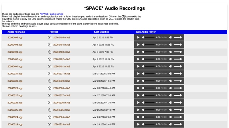 The *SPACE* Amateur Radio over Internet Protocol (RoIP) system offers public audio transmissions from NASA Mission Control and astronauts, primarily for educational purposes. This service streams NASA public media sources, including *Artemis II* and the ISS public audio channel 2 feed, which predominantly features English communications. Astronaut activities on the ISS typically occur between 0700 UTC and 19:00 UTC, with transmissions most common during early mornings USA time, alongside special events such as launches or spacewalks. Users can connect to the live stream via EchoLink to the *SPACE* conference, via IRLP to the 0100 experimental reflector, or via Allstar to node 516221. EchoLink connections utilize the GSM CODEC, while IRLP and other connections default to uncompressed or u-law CODEC. The service notes that long periods of silence are common, and NASA audio sources can be periodically unavailable or noisy. Daily recordings of these transmissions are published at space.rfnet.link/recordings/, available as .ogg audio files for direct playback or .m3u8 playlist files for network streaming in applications like VLC. Each playlist file provides a list of timestamped audio transmissions, allowing users to review specific segments of interest.
 -
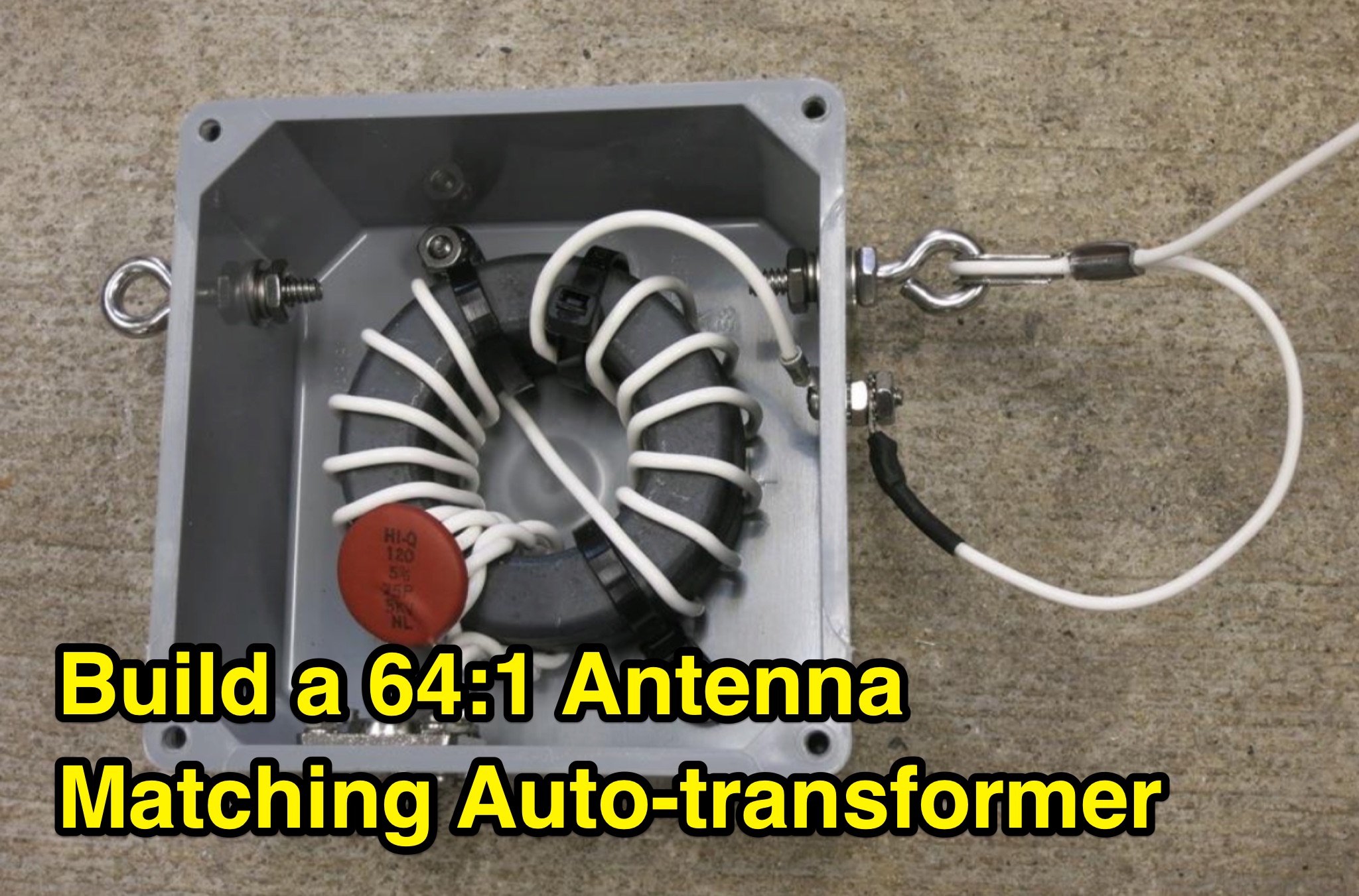 This PDF document provides information on a 64 to 1 antenna matching auto-transformer for ham radio operators. It likely includes details on how to build or use this specific type of antenna matching device, which can be helpful for hams looking to optimize their antenna setup. The document may contain technical specifications, diagrams, and instructions on how to properly implement the auto-transformer. Overall, it serves as a useful resource for hams interested in improving their antenna performance and signal transmission.
 -
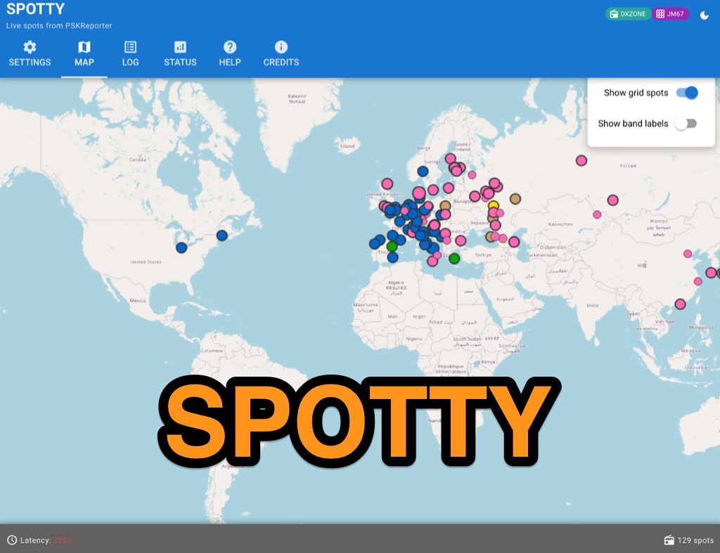 Spotty leverages Philip Gladstone’s pskreporter.info data, delivered via an MQTT broker by Tom Fanning (M0LTE), to offer a responsive web application for visualizing propagation. The Map View presents a default visualization (grid AA00 / callsign MY8CALL) and distinguishes signal types: small spots for signals heard by a location, large spots for transmissions from a location, and teardrop markers for transmissions from the monitored callsign. Clicking a spot reveals detailed signal data in an overlay. The application includes a Log View for raw spot data and a Settings tab for customization. Users can filter tracking by specific Callsign or Grid, with preferences saved to the browser. A notable feature is the Time to Live (TTL) setting, adjustable from the default 60 seconds, which controls spot visibility duration to manage map clutter during high-traffic periods. The tool provides a clear, logic-driven interface for real-time signal monitoring.
 -
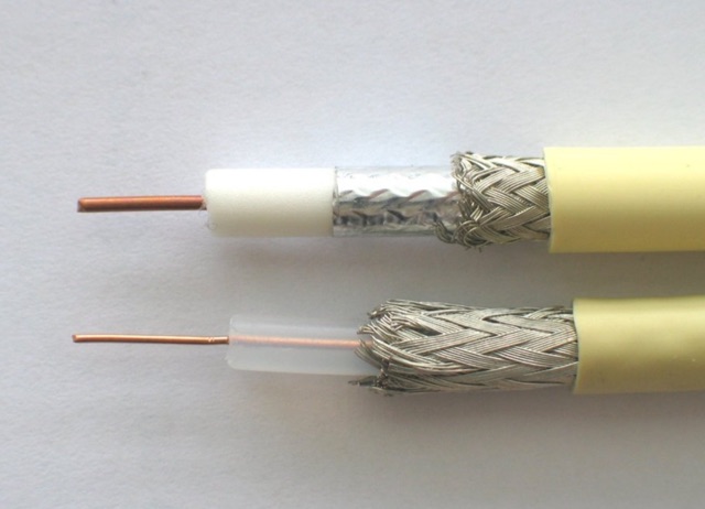 The feed line (also called the transmission line) is the RF power conduit between your radio and your antenna. The quality of your feed line is critical to your station. ARRL Article that explains differences among various commonly used feed line systems
 -
 This Arduino project explores long-range RF communication using EBYTE E32 1W LoRa modules (either E32-915T30D or E32-900T30D) paired with ESP32 microcontrollers featuring OLED displays. The setup leverages the modules' Semtech SX1276 chip with amplifier to achieve up to 1W transmission power—significantly more than the chip alone provides. Unlike other LoRa implementations, these modules include a microcontroller that simplifies interface through UART rather than SPI. The documented implementation includes proper wiring between components and Arduino code that configures the module, displays received messages on the OLED screen, and transmits messages every two seconds while keeping power consumption manageable.
 -
 The most basic form of repeater receives communication on one frequency and re-transmits it on a different frequency, a process known as duplex communication. This capability significantly extends the range of handheld and mobile radios, as repeaters are typically situated at elevated locations with high-gain antennas and greater transmit power. Repeaters commonly operate with FM modulation on the VHF (30 MHz – 300 MHz) and UHF (300 MHz – 3 GHz) amateur bands, which are ideal for portable and mobile devices. Access to repeaters is often controlled by a CTCSS or PL tone, an inaudible signal that prevents the repeater from retransmitting background noise. This mechanism ensures efficient use of the frequency and prevents illegal continuous transmission. Canadian regulations, for instance, require an Advanced amateur radio license and an available frequency within the band to set up a repeater, each assigned a unique call sign and transmit frequency. Configuring a radio for repeater use involves knowing the repeater's transmit frequency, its receive frequency offset (e.g., -600 KHz for VHF or +5 MHz for UHF), and the necessary CTCSS tone. The article references resources like Repeater Book for locating repeaters and provides practical examples for initiating and concluding a basic repeater session, emphasizing clear identification and concise communication.
 -
 The 8m ISM band, a unique frequency range between 10m and 6m, holds potential for amateur radio enthusiasts, yet it remains largely unallocated. This spectrum offers fertile ground for research and self-training. The author's experience with low-power transmissions and WSPR testing highlights the band's capabilities and the need for a narrow, speech-free amateur allocation to encourage experimentation. Discover the world of 8m ISM radio exploration and its future possibilities.
 -
 This project describes the construction of a W3HH (T2FD) antenna for HF bands (3-30 MHz). While less efficient than a tuned dipole, it offers broad frequency coverage with a maximum SWR of 3.4 and reduces QRM (noise) significantly. On the 80-meter band, it shows slightly weaker signals than a dipole but with improved signal-to-noise ratio. The design includes non-inductive resistors, a 13:1 balun, and a "frog ladder" transmission line. Though not a high-performance antenna, it is compact and versatile, making it ideal for wide-band HF communication. Article in French
 -
 This article focus on the radiation angle of vertical antennas and the fundamentals of electromagnetic wave propagation. The calculation of antenna length at 145 MHz is followed by an explanation of electromagnetic wave speed and the link between wavelength, frequency, and velocity. Author discusses the 5/8th wave vertical antenna, namely its performance and the influence of radiation angle on signal transmission. Figures and analogies demonstrate how different antenna types produce distinct radiation patterns. This highlights the importance of selecting the right antenna for a certain purpose, such as local traffic or dxing. The article discusses a variety of factors that affect antenna performance, including SWR, propagation conditions, and equipment dependability
 -
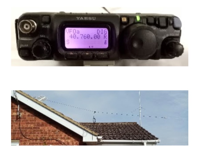
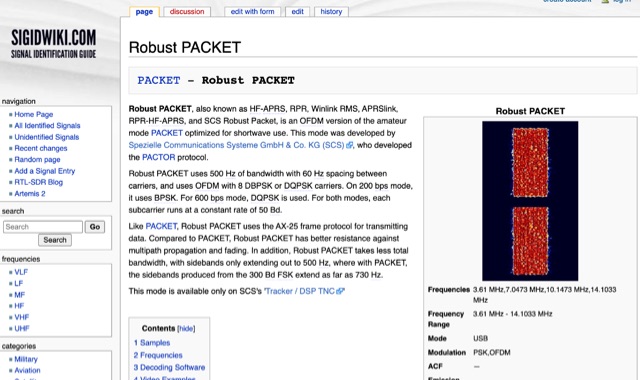 Robust PACKET, developed by Spezielle Communications Systeme GmbH & Co. KG (SCS), is an OFDM variant of the amateur PACKET mode specifically engineered for HF operation. This mode utilizes a 500 Hz bandwidth with 60 Hz carrier spacing, employing OFDM with 8 DBPSK or DQPSK carriers. It supports 200 bps using BPSK and 600 bps with DQPSK, with each subcarrier operating at a constant rate of 50 Bd. Robust PACKET leverages the AX-25 frame protocol for data transmission, similar to standard PACKET. Compared to traditional PACKET, Robust PACKET demonstrates enhanced resilience against multipath propagation and fading effects, critical for reliable HF communications. It also exhibits a more efficient spectral footprint, with sidebands extending only to 500 Hz, whereas 300 Bd FSK PACKET can produce sidebands up to 730 Hz. Operational frequencies for Robust PACKET include 3.61 MHz, 7.0473 MHz, 10.1473 MHz, and 14.1033 MHz, with specific regional frequencies also documented. Decoding software options for Robust PACKET include Wavecom W-Code and Wavecom W-Spectra. The mode is primarily supported by SCS's 'Tracker / DSP TNC' hardware.
 -
 This article provides an overview of setup Direwolf and QtTermTCP for HF packet radio operations. It covers important tasks such as setting up a Direwolf TNC, connecting with stations, and engaging in packet-based chat (K2K). It also looks at how to use nodes as relays and access basic BBS services. The paper also includes HF packet network etiquette recommendations and a description of how to handle common packet transmission issues, making it a useful resource for amateur radio enthusiasts.
 -
 This presentation offers a beginner's guide to digital communication modes in Ham Radio, specifically PSK31 and RTTY. It covers the basics like what data modes are and the equipment needed (radio, computer, interface). It explains the technical details like PSK vs. RTTY, AFSK vs. FSK, and data transmission processes. The presentation also provides instructions on software setup, live testing procedures, and where to find data transmissions on different bands. Finally, it covers communication styles and etiquette for data QSOs.
 -
 Protect your radio tower and solar charged battery power supply by sending the correct Morse code transmissions. Tap out alphanumeric characters in Morse code to prevent your radio station from being destroyed by the Morse code meteor attack! Meteors may be destroyed in any order. All levels start with a fully charged battery. Each DIT uses 1% battery power. Each DAH uses 3% battery power. Your battery charges at a nominal rate of 1% every 5 seconds, and total charge increases by 1% for every correct Morse code transmission. In addition, you have two solar panels that each contribute 1% to the battery charge rate. If your solar panels are destroyed, there are no replacements for that game. When your battery runs low, an SOS prosign bonus appears. Destroy this entity to recharge your battery.
 -
 This PDF file provides detailed information on HF propagation for ham radio operators. It covers the principles of how radio signals travel over long distances, including factors that affect signal strength and propagation. The content is useful for hams looking to improve their understanding of radio communication and optimize their transmissions. Whether you're a beginner or an experienced operator, this resource offers valuable insights into HF propagation that can enhance your communication skills and efficiency on the airwaves.
 -
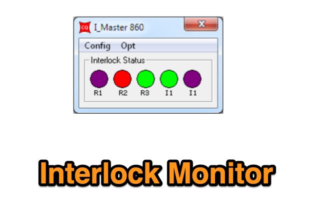 The Interlock Monitor (IM) program allows you to control and monitor the Interlock device from any computer in your network. The Interlock is an equipment designed to be used by contesters where they need to check, supervise and limit, how many radios are in transmission at any given time
 -
 This page offers a tool for hams to design vertical antennas for portable use on different HF/VHF/UHF bands. Vertical antennas provide omni-directional transmission and reception, making them ideal for DX contacts. By adjusting the antenna's dimensions and viewing radiation patterns and VSWR charts, hams can optimize performance in various terrains. The tool also accounts for the impact of sloping ground on elevation radiation patterns. Perfect for hams looking to enhance their portable radio setups and improve long-distance communication.
 -
 This project details an automatic roger beep circuit for VHF/UHF contests. Built around a Microchip PIC microcontroller, the design detects PTT (Push-To-Talk) activation and generates a brief tone upon release, mimicking a "roger beep" to signal the end of transmission. The circuit utilizes readily available components and includes downloadable resources for PCB layout and firmware.
 -
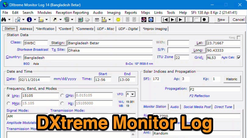 Demonstrates the capabilities of DXtreme Monitor Log 14, a specialized software application designed for radio spectrum monitoring and logging. The resource details its core functionality, which includes logging stations across various bands and supporting multiple transmission modes such as AM, CW, FM, LSB, USB, and RTTY. It highlights features like the ability to select country formats for new databases and the **Schedule Checker** tool, which assists users in identifying broadcast stations for monitoring. The software facilitates tracking **Maidenhead grid squares**, particularly useful for VHF and UHF monitoring activities. It also supports QSL management and offers tools for efficient contact logging, catering to both amateur radio operators and shortwave listeners. Specific information includes its version number, Monitor Log 14, and its utility for DXers and other radio enthusiasts in managing their monitoring experiences and logging contacts effectively.
 -
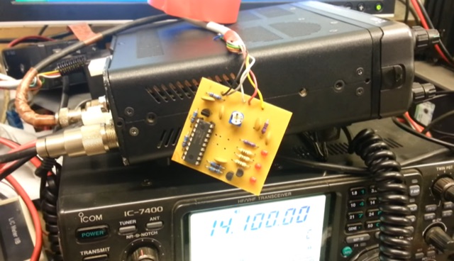
 Integrating a _Software Defined Radio_ (SDR) into an existing ham radio setup involves connecting it with a standard transceiver (TRX), power amplifier (PA), and antennas. The core component is a splitter box that facilitates the connection between the TRX and the SDR, allowing for simultaneous operation without modifying existing equipment. In receive mode, the splitter ties the antenna inputs of both the TRX and a direct conversion receiver (DC RX) together. During transmission, the DC RX input is grounded via a fast telecom relay controlled by the transceiver's -SEND signal, incorporating a 10ms delay for safety. The splitter box includes a 3.7 dB input attenuator for impedance matching and acts as a protective fuse for the DC RX input. Ground loops are mitigated using common mode balun transformers, while the DC RX input is insulated with a broadband transformer. An audio switch box complements the setup, enabling users to listen to either the main transceiver, the SDR output, or both simultaneously. This configuration ensures noise immunity and safety, with the splitter housed in a screened box made from PCB material. On-air tests, such as the CQ WW 160m CW DX Contest, demonstrate the system's effectiveness, showcasing the SDR's ability to handle crowded band conditions with superior selectivity and dynamic range. The SDR's narrow bandwidth filters and waterfall display provide significant advantages, allowing operators to detect weak signals amidst strong interference. The integration of SDR with conventional radios offers enhanced operational flexibility and performance in challenging environments.