Search results
Query: common
Links: 405 | Categories: 5
-
-
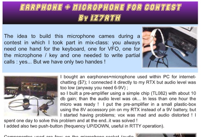 Adapting a common PC earphone with microphone to connect to a transceiver via a homemade pre-amplifier, using a simple chip with aprox 10 db gain. Includes a schematic diagram
 -
 The Nechako Radio Club was formed in the summer of '93 to provide a common meeting point for the local area amateur radio operators.
 -
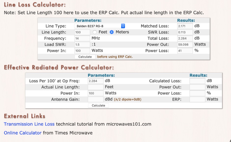 RF Feedline (Coax and Ladder-Line) Loss and ERP Calculators made with Javascript. This complex feddline loss calculator has already several line types paramenters for most common coaxial cables from Belden, Time LMR, Wireman and other common products. Result will give Matches loss, SWR loss, dB and Watts power loss.
 -
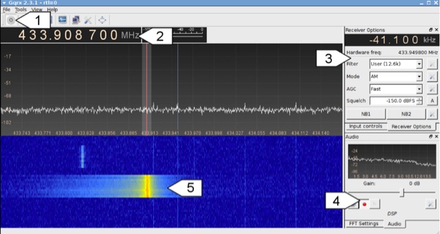 Analyzing 433 MHz radio signals from common wireless devices, such as temperature sensors and remote controls, involves understanding **On-Off Keying (OOK)** modulation. This resource details the process of capturing these signals using a Software Defined Radio (SDR) like Gqrx and then visually inspecting the captured audio data in a sound editor such as Audacity. It differentiates between **Pulse Width Modulation (PWM)** and Pulse Position Modulation (PPM) encoding schemes, illustrating how to identify and decode binary data by eye based on pulse and gap durations. The article provides a step-by-step walkthrough for decoding a wireless thermometer's data, correlating bit patterns with known temperature, humidity, and channel values. It also demonstrates decoding an RF remote control's button presses, highlighting the constant and varying parts of the transmitted packets. The content further introduces automated decoding using tools like RTL_433, explaining its capabilities in parsing various device protocols and showing how to interpret its output, including modulation type and decoded data. Specific examples include analyzing Prologue sensor protocol specifications from RTL_433's source code and noting common operating frequencies like 433.92 MHz in Europe and 915 MHz in the US.
 -
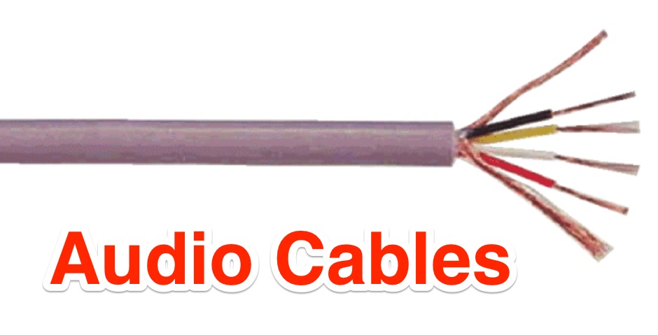 Article with answers to common questions as what cable types to user, cable length, how to join ends.
 -
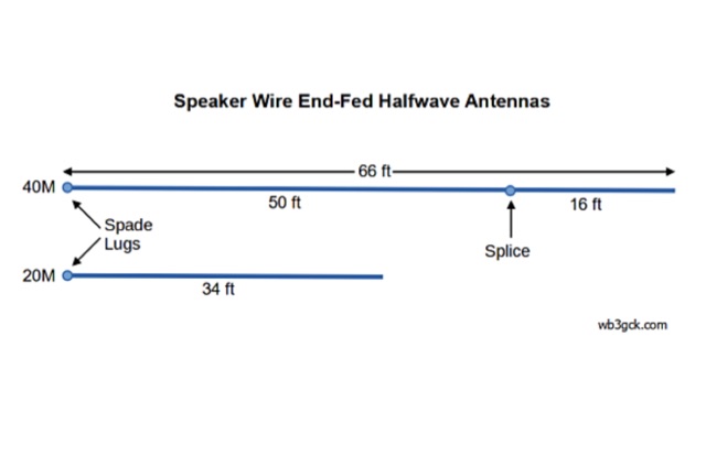 Author experiments end fed half wave antennas using common two conductore speaker wire, this article features a couple of end-fed halfwave wires for the 40M and 20M bands.
 -
 Constructing a dual-band antenna for 40 and 20 meters often involves compromises in size or complexity. This resource presents a compact _open sleeve dipole_ design that addresses these challenges by using 450-ohm ladder line and folded elements to achieve a total length of approximately **17.17 meters**, significantly shorter than a full-size 40-meter dipole. The design leverages electromagnetic coupling, where a primary radiator handles the 40-meter band, and a second conductor resonates on 20 meters without direct electrical connection. This configuration eliminates the need for traditional traps, loading coils, or switching components, simplifying construction and reducing potential loss points. The antenna is fed with RG-58C/U coaxial cable, and a common-mode choke is recommended at the feed point to suppress sheath currents, ensuring a cleaner radiation pattern and minimizing RF in the shack. The design is well-suited for portable operations, field deployments, temporary installations, and restricted urban environments where space is a premium, offering solid performance on both HF bands.
 -
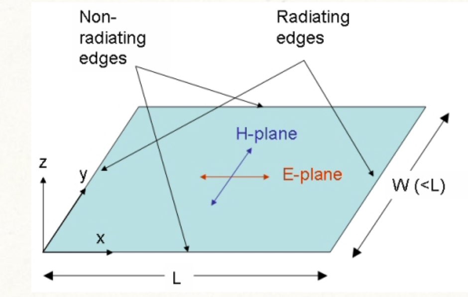 Article about the microstrip patch antennas, and in particular the rectangular, single-polarization microstrip antennas, commonly abbreviated MSA.
 -
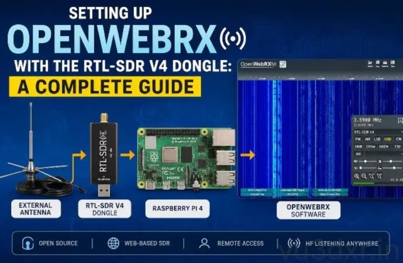 The _RTL-SDR V4_ dongle offers a tuning range from approximately 500 kHz to 1.7 GHz, encompassing HF, VHF, UHF, and microwave amateur allocations, with direct sampling improvements for HF reception. This guide outlines two primary installation methods for _OpenWebRX_ on a Raspberry Pi: utilizing an official Raspberry Pi image or employing a Docker installation. It also provides specific recommendations for Raspberry Pi models such as the 3/3B+, 4, and Zero 2 W, alongside practical advice for antenna selection and placement to optimize reception. _OpenWebRX_ is an open-source, browser-based SDR software package that facilitates web-accessible radio reception. The setup results in a receiver featuring a live waterfall display and demodulation capabilities for AM, FM, SSB, and CW modes. This configuration can be deployed for public access or restricted to a private network, depending on the operator's preference. Further sections address common troubleshooting scenarios and offer tips for mitigating noise, ensuring a stable and effective SDR listening station. The _RTL-SDR V4_ also integrates improved front-end filtering and a software-switchable bias tee, enhancing its utility for various amateur radio applications.
 -
 A 60-foot available space, for example, might necessitate a shortened multiband dipole array to cover 80, 40, and 15 meters effectively. This resource details the construction of such an antenna, combining full-size and coil-loaded dipoles on a single feedline. It addresses the common challenge of fitting multiple HF bands into restricted physical footprints, providing practical guidance for hams with smaller backyards or portable operations. The core of the offering is an interactive calculator that determines required loading coil inductance and dipole lengths for various amateur bands from 160m to 10m. Users input their available space, and the tool provides dimensions, coil turns, and an efficiency rating (Good or Fair) based on the antenna's electrical length relative to a quarter-wavelength. It also suggests suitable _PVC_ pipe diameters for coil forms. The article further illustrates a center feed-point assembly using an 18-inch section of 2-inch _PVC_ pipe, detailing eye-bolt spacing and coaxial connector installation. It emphasizes the importance of adequate spacing between parallel dipoles and offers customization options for the feed-point, including the addition of a _Balun_ for improved feedline isolation.
 -
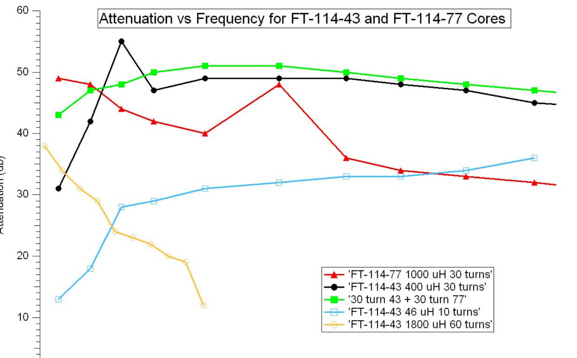 Common mode currents are those currents that flow in the same direction on a wire bundle, as opposed to the currents that flow
 -
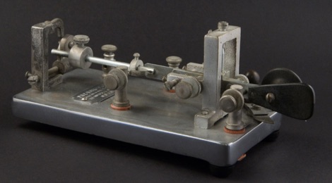 The Vibroplex Collector’s Page details the history and identification of Vibroplex semi-automatic telegraph keys, commonly known as "bugs." It traces the evolution from Horace G. Martin's 1902 Autoplex, which required a battery, to the fully mechanical Vibroplex patented in 1904. The resource explains how these keys generate automatic dots and manual dashes, helping telegraphers mitigate Repetitive Motion Disorder (RMD) and increase sending speed, thus improving their earnings. The site also covers the initial design by Alfred Vail in 1844, Jesse Bunnell's 1881 "Triumph Key," and William O. Coffe's 1904 "Mecograph." This page assists owners in identifying their Vibroplex models and determining their manufacturing dates, providing insights into the company's long history and notable figures like J. E. Albright. It notes that approximately 300,000 Vibroplexes have been produced since 1904, with the Original model still in production after more than 90 years. The resource also touches upon various Vibroplex models, including unusual, scarce, and common types, alongside legal and illegal clones from other manufacturers.
 -
 Article on common Classification of Spy Numbers stations.
 -
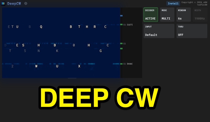 Operating in challenging RF environments, DeepCW provides real-time Morse code decoding capabilities through a neural network model. The software excels at robustly interpreting weak signals, mitigating the effects of QSB, and performing effectively in noisy conditions, a common issue for CW operators. It also supports multi-channel decoding, allowing for the simultaneous interpretation of multiple CW signals present in the audio stream. The application integrates audio pass-through functionality, enhanced with deep-learning-based noise reduction to clean up the incoming audio before decoding. Benchmarking data indicates a 0.00% error rate from 0 to -4 dB SNR, with errors remaining below 1.5% at -8 dB SNR and under 8% at -10 dB SNR across the full range of CW speeds. The project provides comparative analyses against established decoders such as _CW Skimmer_, _fldigi_, and _ggmorse_, utilizing publicly available CW QSO videos from YouTube to demonstrate its performance. DeepCW is designed for cross-platform deployment, supporting Windows, macOS, Android, and iOS operating systems. The core _DeepCW Engine_, which houses the decoding model and a reference implementation, is available separately, offering Python and Node.js examples for decoding from WAV audio files.
 -
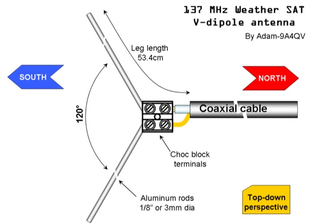 The DIY 137 MHz WX SAT V-dipole antenna project details the construction of a specialized antenna for receiving weather satellite transmissions. It provides specific dimensions for the dipole elements, designed for optimal reception around the 137 MHz band, which is commonly used by NOAA and Meteor weather satellites. The resource outlines the materials required, such as aluminum tubing for elements and PVC for the support structure, along with the necessary coaxial cable and connectors. The article presents a clear, step-by-step assembly process, including how to form the V-shape and connect the feedline. It emphasizes practical considerations for mounting and weatherproofing the antenna for outdoor deployment. The design focuses on simplicity and effectiveness for amateur radio operators interested in satellite imagery. Key aspects include the precise angle of the V-dipole and the lengths of the radiating elements, which are critical for achieving the desired circular polarization response for satellite signals. The resource includes photographic documentation of the construction phases and the final mounted antenna.
 -
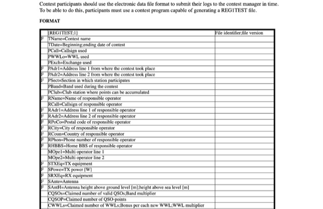 EDI is a common electronic data file format required to submit contact logs. Very popular among contest logs formats.
 -
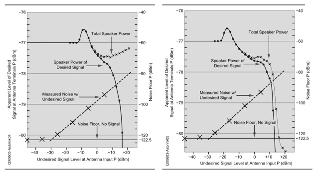 An explanation of the different procedures and definitions that are commonly used for blocking dynamic range (BDR) measurements. Dynamic range in general is the ratio between the weakest signal a system can handle and the strongest signal the same system can handle simultaneously without an operator switching attenuators or turning volume potentiometers
 -
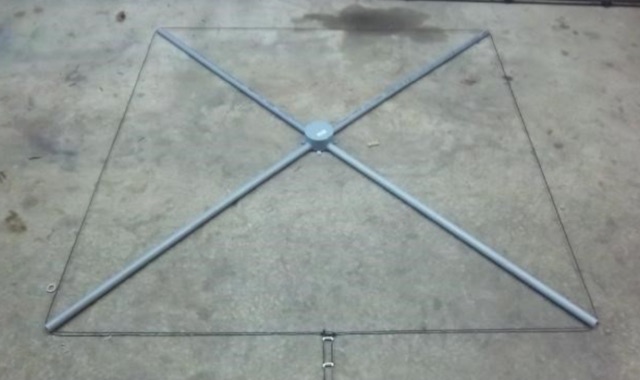 Building A Full-Wave Quad Loop Antenna for 6 Meters. This is an easy antenna to build and the materials cost about $15-20. It exhibits 1.8dB gain over a 1/2-wave dipole. Using an open-wire parallel feedline (commonly called ladder line) with an antenna tuner, it tunes up on the 10m band as a 5/8-wave loop as well
 -
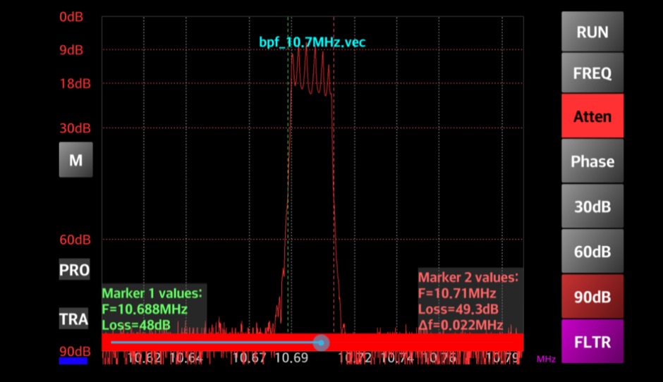 Enables Android users to operate various _miniVNA_ antenna analyzers via Bluetooth, USB, or Wi-Fi, providing a portable solution for RF measurements. The application supports full control over data acquisition, offering features like custom frequency range selection from 1 KHz to the VNA's full range, and automatic screen adaptation for diverse Android device resolutions. It facilitates intuitive, wizard-based calibration for both reflection and transmission modes, saving calibration data for different VNA types (Standard, Pro, Pro with Extender) to avoid repeated procedures. The software displays critical parameters such as SWR, |Z|, Return Loss, Phase, Rs, and |Xs| on 2-axis graphs or Smith charts, with multi-touch gestures for zoom and frequency shift. It includes a frequency generator mode with independent channels and attenuator control for the miniVNA Pro, along with a sweeper function. The cable data mode automatically calculates phase and loss, measures cable length from less than 1 meter to hundreds of meters, and includes a table of common coax cable velocity factors. An experimental X-tal mode measures resonance frequency, Rs, and Q. Data export options include CSV, ZPLOT, and S1P formats, with CSV import capability. The application also features an SM6ENG Audio mode for SWR tuning without visual reference and provides a miniVNA battery voltage indicator. It supports a wide frequency range, with the miniVNA Extender extending coverage up to **1500 MHz**. The application is compatible with Android version 2.2 and later, tested on devices like the _Galaxy TAB 7.7 P6800_.
 -
 256 memories enable the _AT-AUTO_ to recall settings across multiple bands, making it efficient for operators who frequently change frequencies. The tuner is compatible with various antennas and amplifiers, such as the Mercury LUX, and integrates seamlessly with radios like the FLEX 6400 using an RS232-USB connection. This integration allows the tuner to follow frequency changes without additional input, enhancing operational efficiency. Despite being out of production, the _AT-AUTO_ remains supported by Kessler Engineering, which offers firmware updates and repair services. The tuner features a cross-needle SWR meter, providing quick visual feedback during tuning. It also includes a QRO keyline circuit to protect amplifiers during tuning. Users appreciate the tuner's ability to track radios via CAT control, avoiding automatic tuning during QSOs, a common issue with other models. The _AT-AUTO_ is praised for its durability and performance, with many users noting its reliability over years of use. Its ability to handle legal limit power and its balanced line output make it a versatile choice for serious operators. Although it lacks some features like multiple coax outputs found in other models, its robust build and continued support make it a valuable tool for HF enthusiasts.
 -
 Clarifies the intricate process of calibrating the _Elecraft K2_ dial, addressing common user challenges and lively discussions on the Elecraft reflector. Wilhelm, W3FPR, dissects the K2's PLL synthesizer design, chosen for its low phase noise, kit-friendly duplication, and cost-effective components. The resource emphasizes the critical role of the 4000.000 kHz reference oscillator's accuracy during CAL PLL, CAL FIL, and CAL FCTR functions, noting its dependence on temperature and crystal stability for optimal performance. Explaining the K2's frequency display, the document reveals it relies on microprocessor-driven look-up tables generated by CAL PLL for VFO values and CAL FIL for BFO values. In SSB and RTTY, these combine, while CW and CWr modes also factor in the sidetone pitch. The author details inherent limitations, such as the 10 Hz increment resolution of the dial and varying PLL step sizes—from 3 Hz on 160 meters to 10 Hz on 10 meters. BFO increments range from 20 to 35 Hz, collectively limiting practical dial accuracy to within **20 Hz** with diligent effort, or **30 Hz** for a slightly less demanding task. The guide outlines a four-step calibration procedure: setting the reference oscillator, running CAL PLL, running CAL FIL, and setting all BFOs. It highlights the _N6KR Method_ as a particularly easy and accurate approach, requiring only the K2 and a known frequency source like WWV for zero-beating, eliminating the need for external test equipment.
 -
 The Western Washington Amateur Television Society (WWATS) is a group of amateur radio operators in the Puget Sound area with a common interest in amateur television
 -
 Examines various low-band receiving antennas, including the Beverage, Pennant, Flag, and Quad, specifically for deployment in noisy city environments. The resource provides a semi-scientific analysis of common receiving antenna types, focusing on their performance characteristics and practical considerations for urban settings. It details construction parameters for each antenna, such as the use of 9:1 baluns and 300-500 Ohm terminating resistors, and discusses the necessity of preamplifiers for certain configurations. Specific deployment advice includes avoiding radial fields to minimize noise pickup and methods for temporary wire antenna installations. The document provides antenna dimensions, noting a full-size Quad requires 540 feet of wire. Performance observations highlight a Quad variant used by N0XA (AB0X) that achieved 160M CQ WW records and facilitated over 120 JA contacts without a preamp.
 -
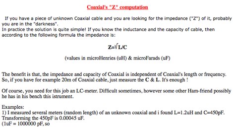 Determining the characteristic impedance (Z) of an unknown coaxial cable, a common challenge for many radio amateurs, can be resolved with a straightforward method. The impedance of a coaxial cable is derived from its inductance and capacitance, and importantly, these values are independent of the cable's length or the operating frequency. This means that measuring a random length of cable, such as 20 meters, provides sufficient data for calculation. The core of this technique involves an LC-meter to obtain the inductance (L) in microHenries (uH) and capacitance (C) in microFarads (uF). The impedance is then calculated using the formula Z = L/C. For instance, a measurement yielding L=1.2uH and C=450pF (0.00045 uF) results in an impedance of 51.6 Ohms, closely matching **RG-58** specifications. Similarly, a TV coaxial cable with L=1.8uH and C=320pF (0.00032 uF) calculates to 75 Ohms. While the accuracy of this method, depending on the LC-meter's tolerance, is approximately 10%, it proves sufficiently precise for practical determination of unknown coaxial cable impedance, as noted by Makis, SV1BSX, who credits Cliff, K7RR, for the formula's dissemination.
 -
 PRO-LINK specializes in the manufacturing and distribution of high-quality cabling solutions, including a wide array of fiber optic cables and various coaxial cable types. Their product line encompasses 50-ohm and 75-ohm coaxial cables, essential for diverse RF applications, alongside specialized RF cables and 10Base-T networking cables. The company also provides a selection of connectors and custom cable harnesses, catering to specific installation requirements. Since 1988, PRO-LINK has offered a 5-year warranty on its products, underscoring a commitment to durability and performance. The product catalog details specifications for different cable constructions, such as _RG-58_, _RG-213_, and _LMR-400_ equivalents, which are commonly used in amateur radio installations for antenna feedlines and inter-component connections. Their offerings support both commercial and amateur radio operators seeking reliable signal transmission. The company's focus on robust cable and connector solutions addresses the critical need for low-loss transmission lines in radio communication systems, ensuring signal integrity across various frequency bands.
 -
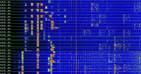 This article discusses how volume reduction can help in the reception of weak signals by reducing the noise level. It is commonly known that reducing the volume also reduces the background noise, and especially in the reception of weak digital signals it can be beneficial
 -
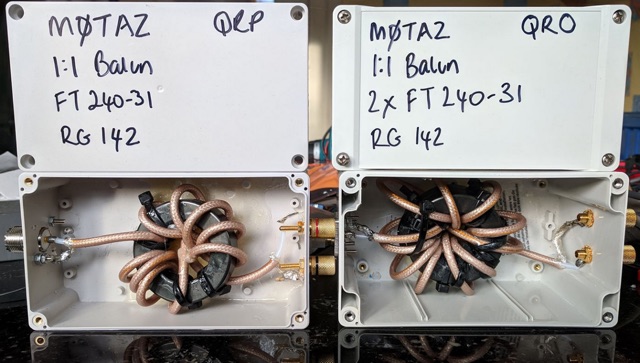 If you want to build your own common mode choke, this article explains how to measure the efficiecy of your choke before using it. In the examples has been used Amidon FT240-31 toroids.
 -
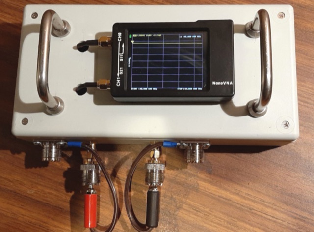 How many times have you heard the advice to coil a few turns of coax at the antenna end to form a choke. How to find out if your common mode current choke really works
 -
 Most Common Service Questions for the Icom IC-R7000 and IC-R7100
 -
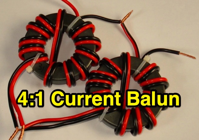 This blog post details the construction and usage of a 4:1 current balun, using two FT240-31 ferrite cores and 12 bifilar turns. It clarifies common misconceptions about using 4:1 baluns with G5RV antennas and ladder-line to coaxial cable connections. M0PZT emphasizes the importance of proper measurements and the limitations of internal baluns in manual antenna tuners. Detailed instructions and considerations for winding and deploying the balun are provided, along with advice on choosing suitable cores and wire for various power levels and frequency ranges.
 -
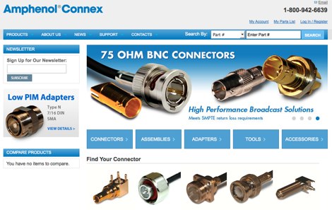 Details Amphenol Connex's product range, focusing on RF connectors, adapters, and cable assemblies. The company produces common radio frequency interfaces such as _BNC_, _SMA_, and _TNC_ connectors, alongside numerous other specialized designs. These components are critical for establishing reliable signal paths in amateur radio stations, ensuring proper impedance matching and minimal signal loss across various frequency bands. The manufacturing process emphasizes precision engineering to meet the demanding specifications of RF applications, from HF to microwave frequencies. Product lines support diverse coaxial cable types, facilitating custom cable assembly for specific station configurations. The extensive catalog provides solutions for both fixed station installations and portable operations, addressing the needs of contesters, DXers, and general amateur radio operators.
 -
 The Sinbad Desert Amateur Radio Club is a general-purpose club that mainly serves the Carbon and Emery Counties but has members from all over Utah and surrounding states. The Club was formed by local Hams in Eastern Utah in 1982 by individuals with a common interest
 -
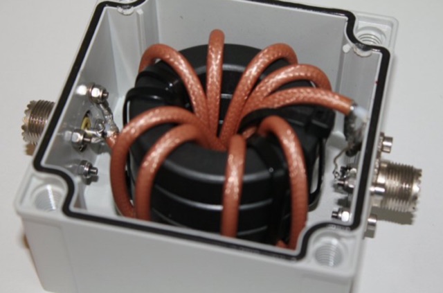 Home brewing a high performance, high power common mode choke for HF bands
 -
 Steve Nichols, G0KYA, presents a practical examination of ground systems for vertical antennas, drawing heavily on the empirical research of Rudy Severns, N6LF. He explains that a robust radial field is crucial for ground-dependent verticals, effectively replacing the antenna's "missing half" and mitigating severe RF absorption in lossy soil. Nichols clarifies that surface radials do not strictly require a quarter-wavelength; instead, deploying a minimum of 16 to 32 shorter wires often yields superior results compared to fewer, longer ones. The presentation also addresses the common SWR paradox: a poor ground might show a perfect 1:1 match, but adding radials, while potentially raising the SWR to around 1.4:1, significantly improves true radiation efficiency. Nichols defines counterpoises as elevated wire networks that substitute for earth connections, offering solutions for limited-space installations, such as the **Folded Counterpoise (FCP)** for 160 meters. This resource provides actionable engineering data for optimizing vertical antenna performance.
 -
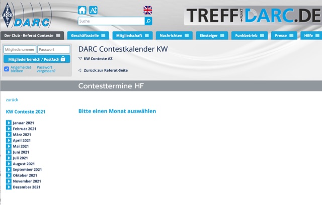 When planning your operating schedule, a reliable contest calendar is an essential tool for any serious contester. This DARC-maintained resource compiles current contest announcements for both HF and VHF/UHF operations, making it straightforward to identify upcoming opportunities for competitive radio sport. My own experience has shown that having a centralized, well-organized calendar saves significant time, especially when targeting specific events like the Clubmeisterschaft Classic (CMC) or the KW-Pokal. The DARC calendar highlights these German and European scoring contests in yellow, providing immediate visual cues for participants. HF contests are clearly marked in blue, while VHF/UHF events appear in red, simplifying band-specific planning. Beyond the major international contests, the calendar emphasizes regional events, which can be particularly useful for those aiming to improve their standing in local club competitions or explore less common contest formats. Special activity periods, such as those spanning multiple days, are also noted with a green background, ensuring operators are aware of extended operating windows.
 -
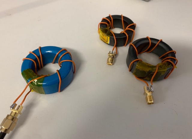 Finding the the best ferrite material for a common-mode choke. How to create efficient ferrite cores and how to measure them
 -
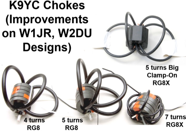 This is a small collection of K9YC info and my experiences. Problems by feed lines of 1/2 lambda length. CMCs in transmitting and receiving systems. Antenna unbalance, Maximal allowed power, Choke winding tips.
 -
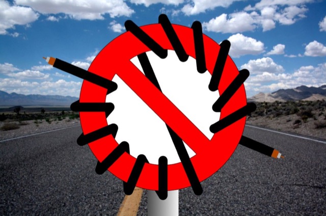 I happened to stumble across some antenna projects showing common mode chokes 1:1 baluns made of some turns of coax wound on T200-2 iron powder toroids.
 -
 Utilizing snap-on ferrite cores and practical insights, the author enhances their shack's cleanliness against electromagnetic interference. With meticulous experimentation and installation, they improve noise levels across HF bands, reflecting on the effectiveness of their filter in minimizing common-mode disturbances. Updates underscore ongoing refinement and cautionary advice for optimal filtering and radio reception amid changing RF environments.
 -
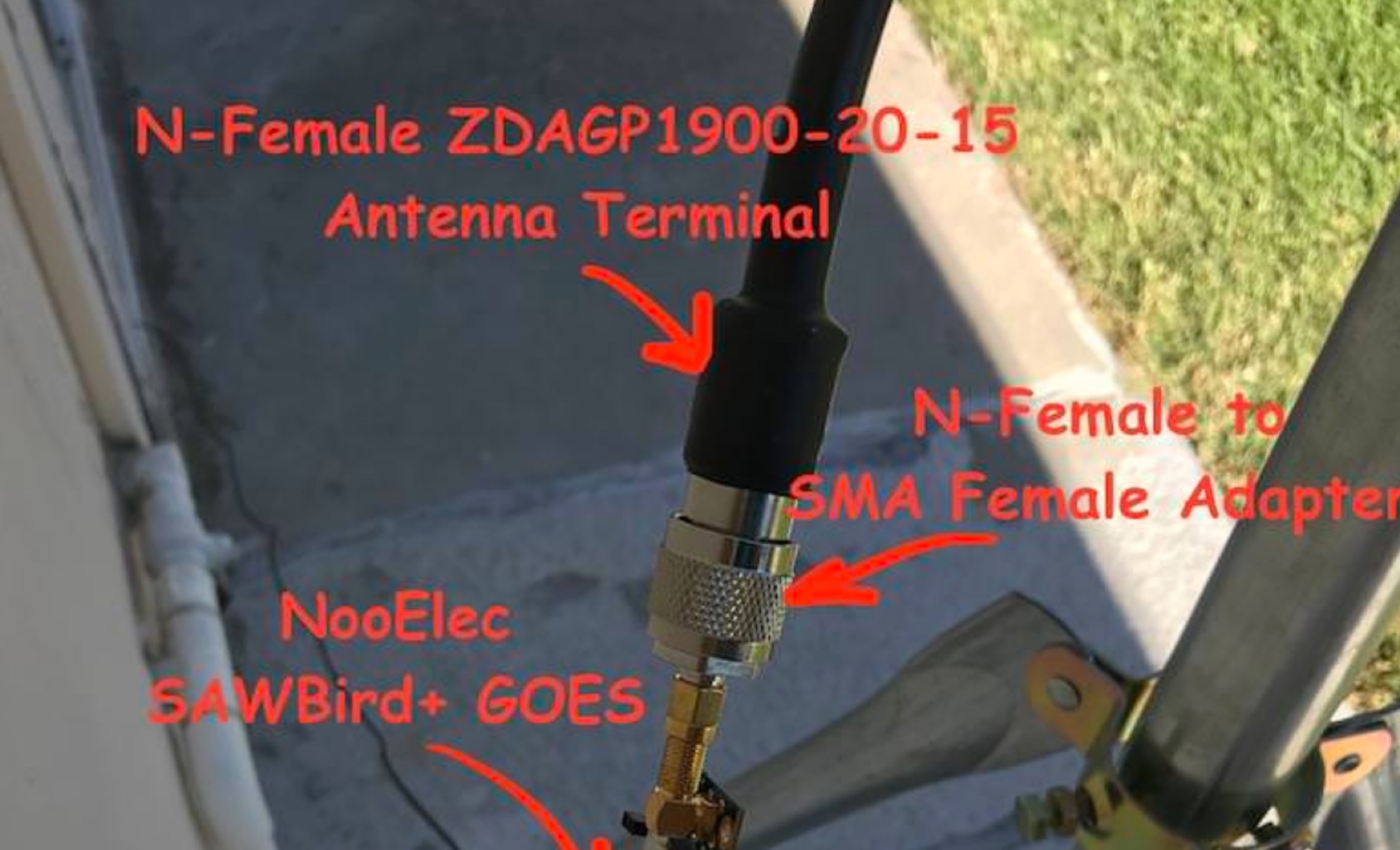 Receiving **GOES-16** and **GOES-17** weather satellite imagery requires a specific hardware and software configuration, detailed in this practical guide. The author outlines the necessary components, including a Raspberry Pi, an RTL-SDR dongle, a suitable LNA with SAW filter for 1.69 GHz, and a parabolic grid antenna. This setup enables direct reception of high-resolution weather data, a fascinating aspect of amateur radio satellite operations. The installation process begins with preparing the Raspberry Pi, followed by updating the system and installing essential dependencies like `git`, `build-essential`, and `cmake`. A critical step involves compiling and installing `librtlsdr` from source, ensuring proper driver setup and blacklisting conflicting DVB drivers. The guide then walks through testing the RTL-SDR dongle to confirm device recognition and troubleshoot common issues like USB power or driver installation problems. Finally, the instructions cover cloning and building `goestools`, a software suite essential for processing the satellite signals. This compilation, while time-consuming on a Raspberry Pi, is crucial for decoding the raw data into usable imagery. The guide concludes with the initial steps for creating the `goesrecv.conf` configuration file, preparing the system for active satellite reception.
 -
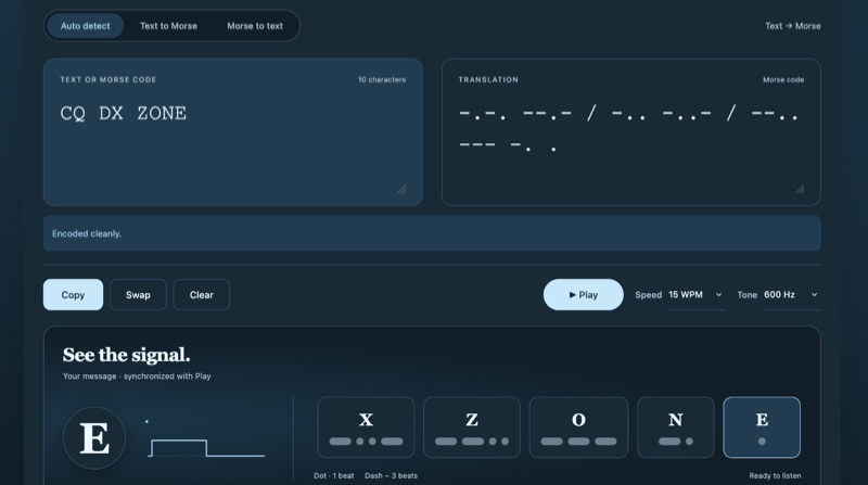 Txtopia provides a browser-based Morse code translator that converts plain text to International Morse Code and decodes Morse back into text, supporting various Unicode dot and dash representations. The tool automatically detects translation direction, normalizes common input variations like middle dots (·), bullets (•), em dashes, and underscores, and explicitly flags unsupported characters or ambiguous sequences with visible placeholders rather than silently dropping them. It accepts spaces, tabs, newlines, and pipes as letter separators, and slashes or blank lines for word boundaries, recording collapsed separators for user review. Users can adjust playback speed from 5 to 40 WPM and tone frequency from 300 to 1000 Hz for CW practice, with playback adhering to international Morse timing. The application operates entirely client-side, ensuring user input remains in the browser without server transmission. It includes a comprehensive reference for the supported Morse alphabet, numbers, and punctuation, aiding in learning and verification. The tool is suitable for checking game clues, verifying tattoo designs, and transcribing messages for ham radio CW practice.
 -
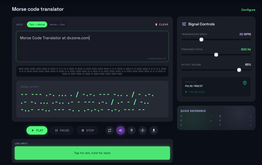 The morsecodeworld.org web application provides an online Morse code decoder and encoder, facilitating real-time conversion between text and International Morse code. It supports adjustable transmission speed (Words Per Minute), sidetone frequency pitch (Hz), and output volume, allowing users to customize their learning and practice environment. The tool includes a quick reference chart for the Morse alphabet and focuses exclusively on International Morse, aligning with contemporary amateur radio licensing and on-air practices, distinguishing it from historical American Morse code. This web-based utility enables users to type text for encoding into Morse audio or paste Morse code for decoding into plain text, offering immediate feedback on timing and character spacing. It supports both visual and auditory learning by providing adjustable parameters for speed and tone. The platform is designed for self-assessment, encouraging users to practice copying and sending, and to identify and correct common errors in character recognition and timing.
 -
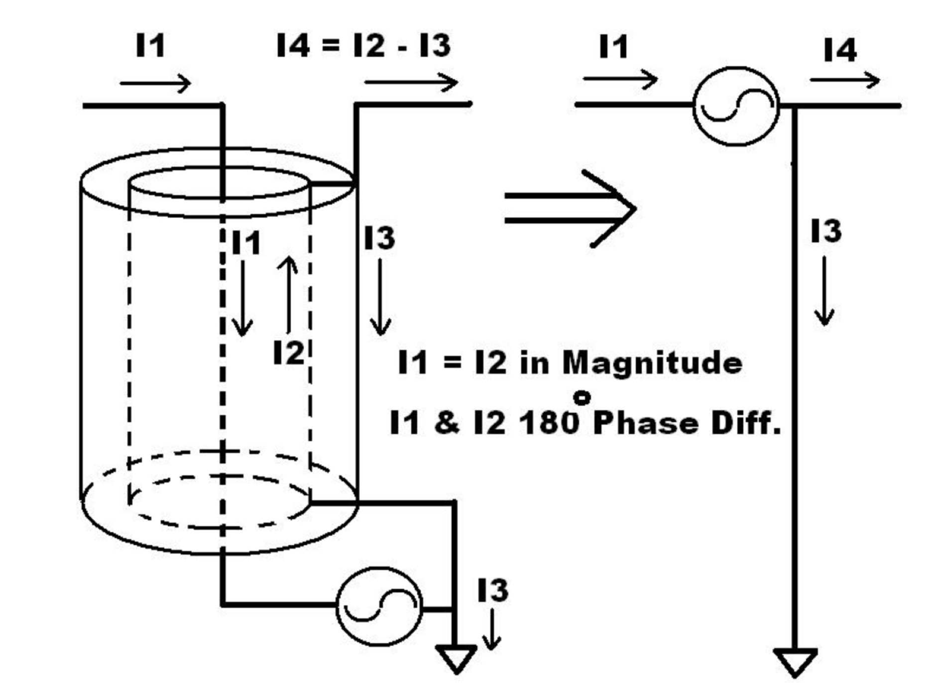 These baluns are used to attenuate the common mode current that flows on the outside of the coaxial feed line.
 -
 Operating an amateur radio station effectively requires reliable coaxial cable to minimize signal loss between the transceiver and antenna. SIVA Cavi, an Italian manufacturer, produces a range of coaxial cables, including specific 50 Ohm low-loss types suitable for amateur radio applications. Their product line features cables like **RG 58 SHF1**, **RG 213 SHF1**, and **RF 400 SHF1**, which are commonly deployed in HF and VHF/UHF setups. The company also offers specialized cables such as the **HF 214 UF Ultraflex**, a high-performance broadband low-loss 50 Ohm cable designed for flexibility and reduced attenuation across various amateur bands. These cables are engineered with solid or foam dielectric materials, impacting their electrical characteristics and suitability for different power levels and frequency ranges. For instance, foam dielectric cables often exhibit lower loss at higher frequencies, a critical factor for VHF/UHF operations. Beyond amateur radio, SIVA Cavi manufactures cables for digital video broadcast, offshore marine use, and fire detecting systems, demonstrating a broad engineering capability in coaxial cable technology.
 -
 A 10-meter half-wave vertical antenna, designed by Thomas 4L/G8BAG, offers a practical solution for hams with limited space and materials. This "flower pot" design utilizes common hardware store items such as 60mm plastic drain pipes and 75 Ohm coax cable, demonstrating that effective HF operation doesn't require specialized components. The author details the coax preparation, including stripping the outer sleeve and braid at specific measurements like **2510 mm** and 2450 mm, and integrating it into the pipe structure. The construction emphasizes simplicity and low cost, providing an accessible path to getting on the air on the 10m band, especially when a horizontal beam is not feasible. The article notes an SWR of _1.5:1_ with 75 Ohm coax, managed by an MFJ 258 for impedance matching. This temporary solution proved robust, withstanding various weather conditions and achieving contacts across continents, including W, VK, BG, G, JA, and VR2, using 100W SSB from Georgia.
 -
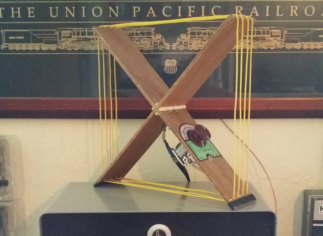 A dual band X-frame wire antenna made using 4 turns for response down to 3 MHz or so, and 2 turns (switched) for response up to around 18 MHz. The loop configurations are tuned using common eBay 365 pF tuning caps.
 -
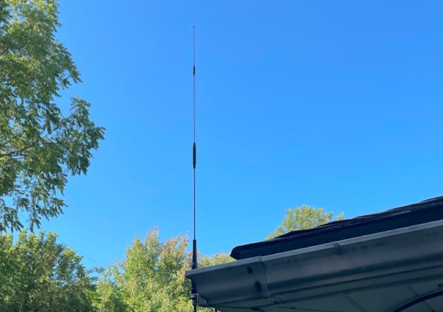 A concept to use common, low-cost parts to mount a VHF/UHF dual-band antenna to help people who have HOA restrictions, are renters, or desire low-visibility characteristics get on the air.
 -
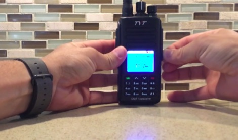 Common issue on the TYT MD-390 when the speaker start sounding like it is broken, but it depends by the external mic cover.
 -
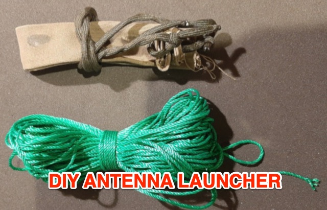 This article explores budget-friendly methods for launching wire antennas into trees, comparing common options like slingshots and professional arborist tools. The author introduces a simple and cost-effective DIY approach using latex balloons, sand, and readily available materials for efficient antenna deployment in the field