Search results
Query: eme antenna
Links: 743 | Categories: 9
Categories
- Antennas > 6M > 6 meter Yagi Antennas
- Antennas > Antenna Books
- Software > EME
- Radio Equipment > HF YAGI Antennas > Hy-Gain TH3JR
- Technical Reference > Lightning Protection
- Operating Modes > WiFi > Long Range WiFi
- Antennas > Maria Maluca
- Antennas > Feed Lines > Open Wire
- Technical Reference > Standing Wave Ratio
-
 This article summarizes probably the most extensive numerical modelling calculations on the helical antenna ever performed.
 -
-
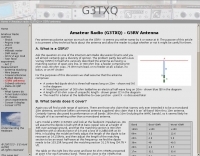 Review by G3TXQ and comparison to its modificated versions. SWR Measurements on inverted V setup and comparison from EZNEC model and a real one.
 -
 About beverage antennas, Enhanced F/B Beverages, Bandwidth of Directivity, arrays. This article describes two phasing systems for Beverage antennas that improve directivity and cancel rearward signals. These systems use lossy elements and require minimal components to achieve broadband performance.
 -
-
 Presents the design and performance of a 4-element wire Yagi antenna for the 40-meter band, building upon VE3VN's earlier 3-element switchable wire Yagi. The resource details the antenna's evolution, highlighting the transition from a 3-element to a 4-element configuration and the resulting improvements in gain and front-to-back ratio. It provides specific insights into the antenna's construction and expected operational characteristics. VE3VN shares insights from field results, noting the antenna's performance on 40 meters. The discussion includes the antenna's pattern and matching characteristics, crucial for any DXer or contester looking to optimize their signal on this popular HF band. The author's experience with the previous 3-element design informs the enhancements made to this 4-element iteration. The article includes a visual representation of the antenna's current view, offering a practical perspective on its physical layout. It serves as a valuable reference for hams considering a directional wire antenna for 7 MHz operations, demonstrating a practical approach to achieving enhanced directivity and gain.
 -
 Demonstrates the design and construction of a compact, portable multi-band mini-delta loop antenna, specifically optimized for /P (portable) operations from remote locations like Scottish islands. The resource covers the theoretical underpinnings of half-wave loops, contrasting closed and open configurations, and then details the application of a folded dipole principle to achieve a 50-ohm match for direct coax feed. It presents empirical formulas for calculating element lengths, considering the velocity factor of common wire types, and provides a detailed example for a 20m (14.175 MHz) version. The article includes a comprehensive table of dimensions and allowances for a five-band (20m, 17m, 15m, 12m, 10m) mini-delta beam, along with construction hints for the central support and balun. It specifies a 1:1 trifilar balun wound on a ferrite rod and describes the antenna adjustment process using an _MFJ-259B Antenna Analyser_. Initial test results indicate an SWR of 1:1 at resonance and a bandwidth of approximately 240 kHz on 20m, even at a low height of five feet above ground. The distinctive utility lies in its focus on a practical, easily deployable beam antenna for portable DXing, offering a viable alternative to more complex or larger arrays.
 -

-
 An home made SWR meter for 2.4 GHz. A DIY SWR meter that allow precise measurements and calibration of any WiFi antenna. This is test equipment everyone who build wifi antennas should have in their shack. Article is in french and include some videos.
 -
 GW4ALG's _136 kHz Pages_ document the evolution of vertical antennas for the 2200m band, starting with a prototype mounted on a house wall. This initial design, despite achieving the first **395 km** GM-GW QSO, suffered from significant insulation breakdown, high RF losses due to proximity to the house, and difficult tuning adjustments. The author details the challenges of maintaining resonance and matching with a variometer in the loft, noting that adding three earth spikes offered no measurable improvement over a simple water tap connection. The subsequent experimental 12m vertical, relocated away from the house, significantly reduced dielectric losses and proved far more effective. This antenna enabled GW4ALG to set a world DX record on 136 kHz with a **1916 km** QSO to OH1TN, and an intra-UK record of **703 km** to GM3YXM/P. The resource further explores the use of helium-filled balloons to extend the vertical radiator, achieving heights up to 27m, typically 20m, for enhanced low-band performance. Practical advice on balloon types, inflation, and critical insulation between the wire and balloon is provided, emphasizing safety and avoiding arcing.
 -
 Demonstrates the construction and measurement of a single-turn HF receiving loop antenna, built from common materials like electrical conduit and lamp cord. The resource details the physical dimensions, including a 4-meter circumference, and calculates the theoretical inductance at approximately _6.4 uH_. It outlines a method for determining resonant frequencies across the 4-17 MHz range using a _C Jig_ and a _VR-500 receiver_, coupling the loop with a ferrite ring. The article also discusses the impact of receiver coupling on the loop's Q factor, noting a degradation in sharpness due to the transformer's reflected impedance. Analyzes the observed resonant frequency patterns, highlighting an unexpected rise in the loop's effective inductance at higher frequencies, particularly above 13 MHz. While some increase is attributed to distributed capacitance, the rate of rise suggests further investigation. The experimental setup provides practical insights into the challenges of maintaining high Q in simple receiving loops and offers a comparative reference for other homebrew antenna projects, such as those by _VK2TPM_.
 -
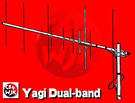
 On this page is the design for Dual Band 2M / 70cm antenna with 3.2mm elements. The antenna has a 50 ohm designed driver. This Yagi has a unique element called a Open Sleeve
 -
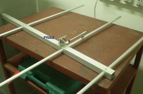 A 3 element yagi antenna project for the 144 MHz band by PY5ALZ in portuguese
 -
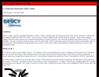
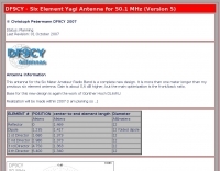 Christoph petermann's df9cy six element yagi antenna for six meter band
 -
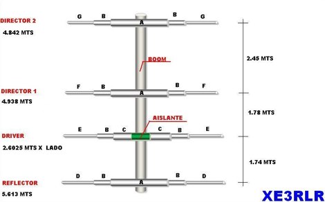
 Design plan of an array of a two element yagis for 80m and a 3 element 40m antenna sharing a single 12 meters long boom by EA5DY
 -
 The document provides a detailed guide on modifying an inverted-L antenna to include the 160 meters band. This enhancement allows amateur radio operators to utilize the lower frequency effectively, which is crucial for long-distance communication, especially during the night. The inverted-L design is popular due to its compact size and ease of installation, making it suitable for various environments. By adding top band capabilities, operators can engage in DXing and contesting on 160m, expanding their operational range and opportunities. The guide includes practical tips and considerations for construction, ensuring that the antenna maintains its performance across the extended frequency range. It discusses the necessary adjustments and materials required for the modification, along with potential challenges and solutions. Whether you are a seasoned operator or a beginner, this project can enhance your station's capabilities, allowing for more versatile operations and improved signal quality on the 160m band.
 -
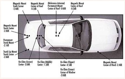
 A 500-watt mobile antenna project details the conversion of an old 10m hamstick into a highly efficient, multiband "bugstick" for HF operation. The core modification involves replacing the original coil with 25 turns of 6 turns-per-inch, 1.5-inch diameter coil stock, fabricated from #14 wire. This design, intended for a 3-magnet mount on a vehicle cab, achieves resonance on multiple bands by shorting out specific turns on the coil, similar to a **bugcatcher** antenna. Measurements taken with an MFJ-259 analyzer on a GMC pickup show 0 turns shorted for 20 meters (14.2 MHz), 10 turns for 17 meters, 16 turns for 15 meters, 19 turns for 12 meters, and 23 turns for 10 meters. The construction emphasizes using UV-resistant tie-wraps and #14 solid wire with crimp lugs for robust RF connections, bypassing the fiberglass rod for current flow. A bonus section details a 40-meter version, utilizing 48 turns of 8 TPI, 2-inch diameter coil stock.
 -
 Construction details and tests about a 2 elements cubical quad antenna for HF Bands (20,17,15,12 and 10m band).
 -
-
 A project for a home made 5 element yagi-uda antenna for 2 meters, covering 144-148 MHz band by N1BMX
 -
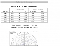
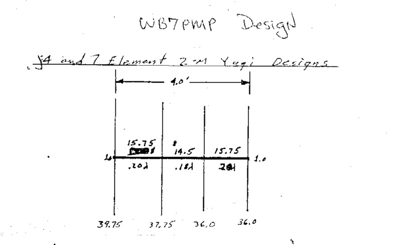 Original drawing and design of a 4 and 7 elements yagi antenna for 50 Mhz
 -
 SimSmith is a highly interactive, real time Smith chart graphing program. Circuits are constructed using drag-n-drop. Load files can be imported from the EZNEC and CocoaNEC antenna simulation software and from the AIM4170 and miniVNApro antenna analyzers. Circuits and load files can be of any size. Key Features: SimSmith is one of the few Smith chart packages which models transmission line losses. SimSmith also allows the description of circuit elements using algebraic equations. SimSmith has only one screen and allows the screen to be resized to increase workspace or readability.
 -
-
 Collection of different techniques to homebrew PVC yagi antennas, including elements assembling, baluns and chokes, radiator box tips and tricks by dk7zb
 -

-
 This document details the design and construction of a Vinecom 6N4 dual-band Yagi antenna for the 50MHz (6-meter) and 70MHz (4-meter) amateur radio bands. The antenna features 9 total elements (4 elements for 50MHz, 5 elements for 70MHz) on a 4.236-meter aluminum boom. Computer simulations using MMANA software predict 7.21 dBd gain on both bands with front-to-back ratios of 16.01dB (6m) and 15.37dB (4m). The design uses 12.7mm diameter elements mounted on a 32mm square boom, weighing 5.7kg total. Practical measurements with an MFJ-269 analyzer confirmed good SWR performance across both bands after element length adjustments.
 -
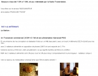
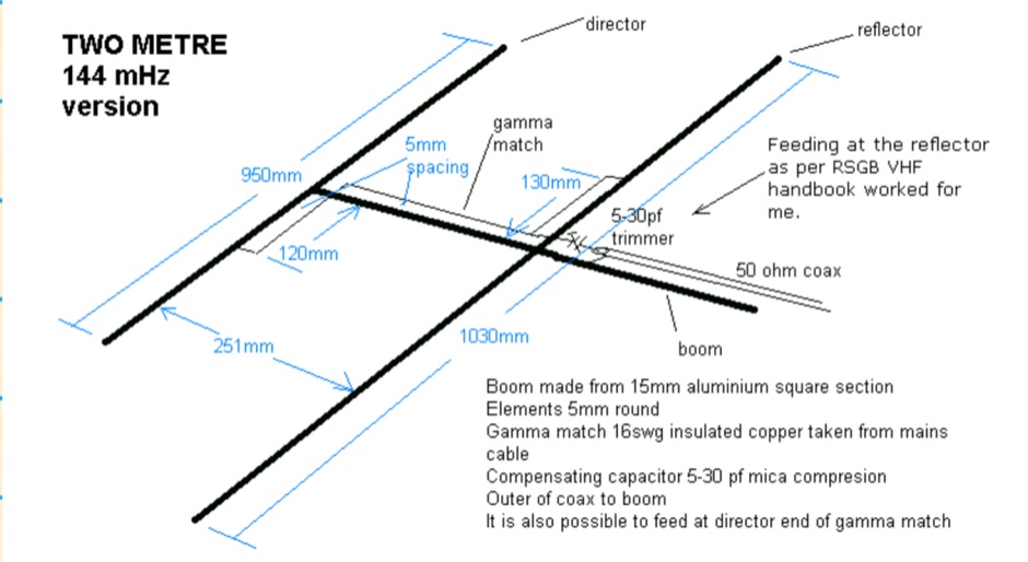 The HB9CV is a well known two element antenna of a directional beam type with a forward gain of 4 to 5 dBd. This one is for two metres but it can be scaled, from the dimensions in the diagram, for other bands I have also made them for four and six metres
 -
 YF1AR multiband vertical antenna, based on orginal concept by VE7BS. Consist of 6 vertical elements and 6 base radials with a single 50 Ohm feed line.
 -

-
 A re-usable control & computing platform for antenna measurement, PSK31 digital modems, audio filtering, signal source & VFO, memory keyer by AMQRP
 -
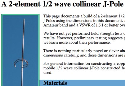 This article document a 2 element half wave collinear J-Pole antenna by KC9EOT and KB8OJH
 -
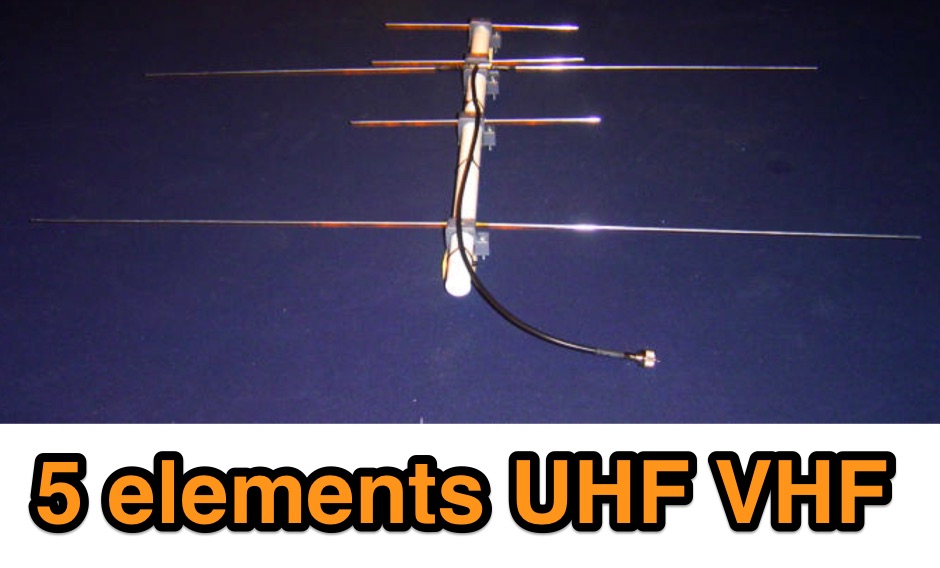
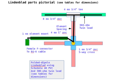 This document contains the detailed instructions to build a homemade lindenblad antenna using a twin-lead as dipole elements. This document contains 9 pages and includes a detailed construction sequence and some drawings to build this antenna for UHF and VHF ham radio bands
 -
-
-
-
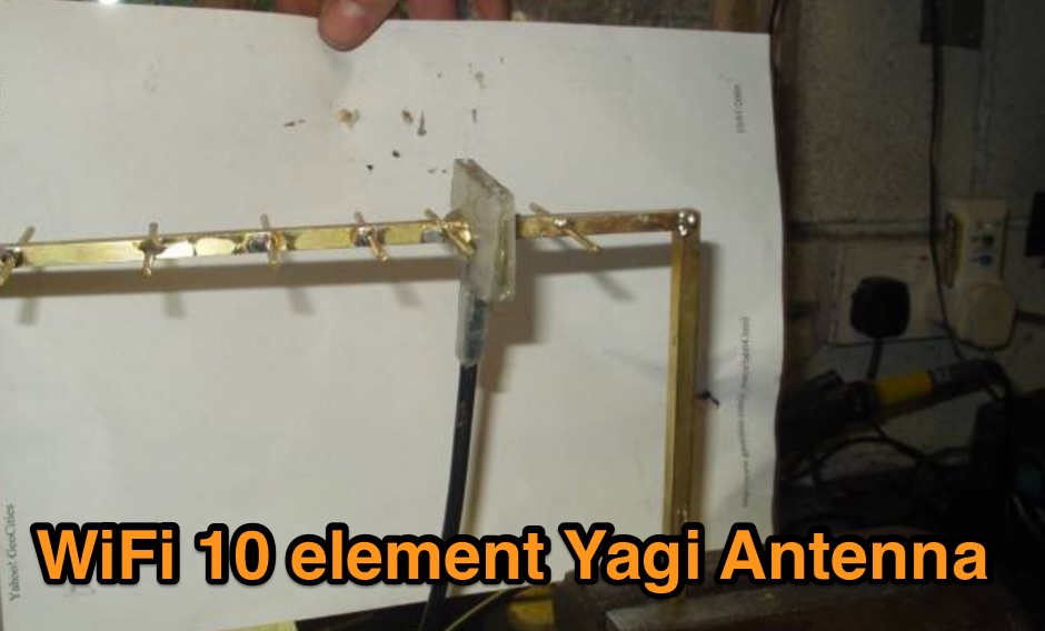 A DIY project of a WiFi 10 elements Yagi antenna
 -
 Accurately determining an antenna's feedpoint impedance is crucial for optimal performance, especially when experimenting with new designs or making adjustments. While SWR meters provide basic information, a full complex impedance measurement reveals the resistive and reactive components, which are essential for proper matching. Modern antenna analyzers, like the _Palstar ZM30_ or MFJ259B, simplify this task, but measurements taken through a transmission line require careful interpretation due to impedance transformation. This resource details a calibration method to precisely account for the effects of the feedline. It explains how a transmission line can significantly alter the measured impedance, illustrating this phenomenon with a Smith Chart example where an 80m antenna's [22 + j6] Ohms feedpoint impedance transforms to [82 + j45] Ohms after a 10m line. The guide demonstrates using a transmission line calculator applet, such as the one by W9CF, to reverse this transformation. It outlines the process of calibrating a specific length of RG174 coax, showing how an initial 26ft estimate was refined to **25.85ft** to accurately predict a known 22 Ohm load, significantly improving accuracy over uncalibrated results.
 -
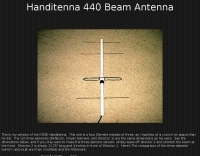 A 4 elements handitenna for 70 cm band. This is my version of the K5OE Handitenna. This one is a four Element instead of three, as I had less of a crunch on space than he did. The 1st three elements (Reflector, Driven Element, and Director 1) are the same dimensions as his were.
 -
 A 70cm and 2m 6 elements yagi antenna plan based on the IEEE Transactions on Antennas and Propagation
 -
 DF9CY implementation of W1HIS suggestion of inserting a common mode choke into a 40m antennas feed-line.
 -
 A 5 band two element quad antenna working from 20 to 10 meters using hardware-store parts or modifying an existing commercial triband quad by KC6T
 -
 An inverted triangle Delta Loop Antenna for the 40 meter band made with aluminium pipes, each element is 14,2 meters including a home made aluminium mount.
 -
-
 Selecting appropriate cabling for amateur radio installations, whether for antenna feedlines, control lines, or station wiring, is critical for optimal performance and safety. This resource provides access to a manufacturer specializing in a broad range of electronic and electrical cables, including options suitable for various ham radio applications. Their product line encompasses standard and custom cable solutions, designed to meet specific operational requirements for both indoor shack setups and outdoor antenna systems. The company emphasizes _proven quality_ and compliance, with products certified by the Canadian Standards Association (CSA), Underwriters Laboratories (UL), and Intertek (ETL). Their quality management system is registered to _ISO 9001:2015_, ensuring consistent product standards. They offer competitive pricing and utilize AI-logistic tools for reliable on-time delivery, serving customers globally with technical support. Access to detailed technical specifications and an online quote tool is available for registered site members, facilitating precise cable selection for projects requiring specific impedance, shielding, or environmental ratings.
 -
 The NCDXF/IARU International Beacon Project operates a worldwide network of 18 high-frequency radio beacons, continuously transmitting on 14.100, 18.110, 21.150, 24.930, and 28.200 MHz. These beacons, initially launched in 1979 with a single station and expanded to the current 18-beacon system in 1995, provide reliable signals for both amateur and commercial users to assess current **ionospheric propagation** conditions. The system's design, construction, and operation are managed by volunteers, covering hardware and shipping costs. The resource details the evolution of the beacon network, including the transition from Kenwood TS-50s transmitters to Icom IC-7200 radios with a new controller design implemented in 2015. It explains how listening for these 100-watt signals, transmitted to vertical antennas, allows operators to determine band openings and optimal propagation paths globally. The content also references three QST articles providing historical context and technical specifics of the beacon project. Practical information includes methods for identifying transmitting beacons via a schedule or specialized software like FAROS and Skimmer, which integrates with the **Reverse Beacon Network** for automated monitoring.
 -
 A Loop Fed Array Yagi antenna for 50 MHz featuring 11 dBi gain and 23 f/b ratio. In this excellent page the author even includes a detailed drawing in DWG format, with element lenght and spacing measures, in a separa file a full list of material list needed to build this yagi antenna including source and price, the EZnec file for this antenna plan, and a lot of pictures of this LFA Yagi for 50 Mhz. A ten page PDF file containing all infos, is also available to download.
 -
 TurboLog is a station management and logging program designed for amateur radio operators, providing robust database and logging functionalities. It features fully integrated support for controlling typical radio station equipment, including transceivers, packet radio TNCs, Morse and voice keyers, and digital mode terminals. The software also incorporates antenna switching capabilities and acoustic alerting, streamlining station operations for DXing and contesting. The program's utility extends to award tracking for entities like DXCC and IOTA, alongside comprehensive callbook and ham database integration. It supports log import and export, QSL label generation, and includes TNC drivers for packet radio. The trial version allows users to evaluate its extensive features before commitment, making it a versatile tool for managing complex amateur radio station configurations and operational data.
 -
 Demonstrates the construction of a 144 MHz turnstile antenna, detailing its design for omnidirectional, horizontally polarized VHF operation. The resource outlines the physical dimensions and materials required, including specific lengths for the radiating elements and the use of _RG-58_ coaxial cable for phasing. It covers the assembly process, emphasizing the critical spacing and connection points to achieve the desired radiation pattern and impedance matching for the _2-meter band_. The article presents measured _SWR_ performance across the 144-146 MHz segment, showing a low SWR of 1.2:1 at 144.5 MHz, which is suitable for general VHF use. It compares the turnstile's performance to a 9-element Yagi, noting the turnstile's advantage in providing consistent signal strength from all directions without requiring a rotator. Practical application for local FM simplex and repeater operations is implied, offering a simple yet effective antenna solution for fixed or portable stations.
 -
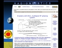 Unlocking the full multiband potential of the 225 Ohm elementary radiator in a folded monopole, dipole-like or turnstile layout, by Francesco Errante
 -
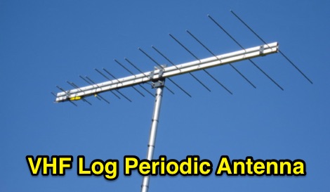 17-Element Very High Frequency/Ultra High Frequency Log Period Dipole Array