Search results
Query: all band antenna
Links: 491 | Categories: 9
-
 Documents the OC1I and OC6I IOTA DXpeditions to Peru, specifically highlighting operations from SA-098 (Isla La Leona) and SA-076 (Isla Lobos de Afuera). The OC1I team logged over **8000 QSOs** from SA-076, while OC6I made 1400 QSOs from SA-098, despite challenging propagation conditions. The resource details the equipment used, including an _IC-7000_, an IC-706mkIIG, and a TS-440SAT, along with various antennas such as a 160m dipole, FD4, G5RV, and a multi-band vertical for 17m, 20m, 30m, and 40m. The DXpedition dates are specified: OC6I operated from SA-098 between December 28 and December 30, while OC1I was active from SA-076 from January 2 to January 7. Both operations are confirmed as valid for IOTA credit. The page also includes a video link for the OC6I operation and a photo gallery from the DXpedition. Feedback is welcomed, and the webmaster is identified as Bodo Fritsche, DL3OCH.
 -
 Explains the annual Jamboree on the Air (JOTA) event, a global amateur radio gathering for Scouts and Guides. This activity connects young people worldwide through ham radio, fostering international friendship and introducing them to radio communication technology. Participants use various amateur radio bands and modes, including HF, VHF, and digital modes like FT8 and JS8Call, to make contacts with other JOTA stations and learn about the hobby. The ARRL provides resources for Scout leaders and amateur radio operators interested in hosting a JOTA station, including guidelines for setting up temporary stations, safety protocols, and educational materials. The event typically occurs on the third full weekend of October, aligning with the World Organization of the Scout Movement's (WOSM) global schedule. JOTA emphasizes hands-on experience with radio equipment, antenna theory, and basic operating procedures. It serves as a significant public service opportunity for hams to engage with youth and promote the educational aspects of amateur radio.
 -
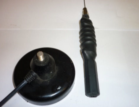 This article is about a home made project of a whip antenna for 2 meters band. Includes lenght of whip for all frequencies from 140 MHz to 151 MHz both in mm and inches
 -
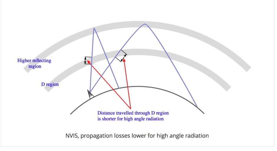 Near Vertical Incidence Skywave propagation is a form of radio wave propagation used on the MF and HF bands to provide radio communications and broadcasting coverage over short distances, especially where the terrain contains obstacles.
 -
 A great and efficient monoband VHF portable antenna. The article consist of two version of a 12.5 Ohm 3 elements yagi beam antenna plans for the two meter band, a full sized and a shortened version expecially designed for the SSB and CW on 144 MHz.
 -
 Presents field test results for an **elevated SuperAntenna MP-1** portable antenna, configured on a tripod for HF operations. The resource details the antenna's setup and performance during a portable activation, focusing on its use across the 40-meter, 20-meter, and 17-meter amateur bands. It includes observations on signal reports and operational considerations for this specific portable antenna configuration. The content provides practical insights into deploying the MP-1 antenna in a non-ground-mounted setup, which is often a point of interest for portable and QRP operators. It documents the author's experience with the antenna's tuning and effectiveness for making contacts under real-world conditions, offering a user-perspective review of its capabilities. The article also features photographic evidence of the antenna's deployment, illustrating the tripod mounting and the overall portable station setup.
 -
 Installing a mobile rig in a vehicle requires careful planning and execution to ensure optimal performance and safety. The process begins with selecting the right equipment, such as the ICOM IC706MKII for low bands and the ALINCO DR-610 for VHF/UHF operations. Proper mounting is crucial; both radios are strategically placed under the back seat of the Silverado, allowing for a clean installation while maintaining passenger comfort. The Hustler antenna, equipped with various resonators, ensures coverage across multiple bands, while the LDG automatic antenna tuner fine-tunes the match for efficient operation. A remote head for the tuner enhances accessibility, making adjustments easier while driving. Each step of the installation is documented to provide insights and tips for fellow operators looking to enhance their mobile setup. The experience shared here reflects practical knowledge gained through hands-on work, aiming to inspire others in the ham community to undertake similar projects.
 -
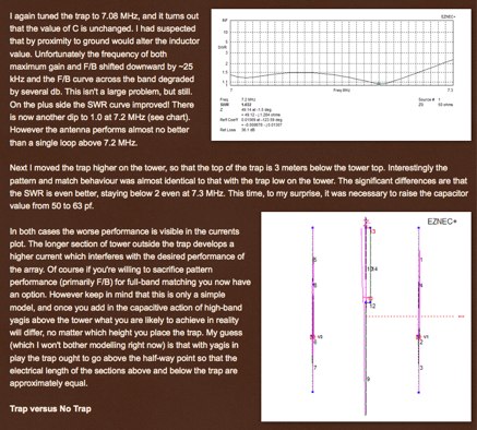 It is possible to detune the tower so that, at least on one band, the tower can be made to effectively disappear. That is, become non-resonant on the band of interest. This allows the vertically-polarized low-bands antenna to meet its potential.
 -
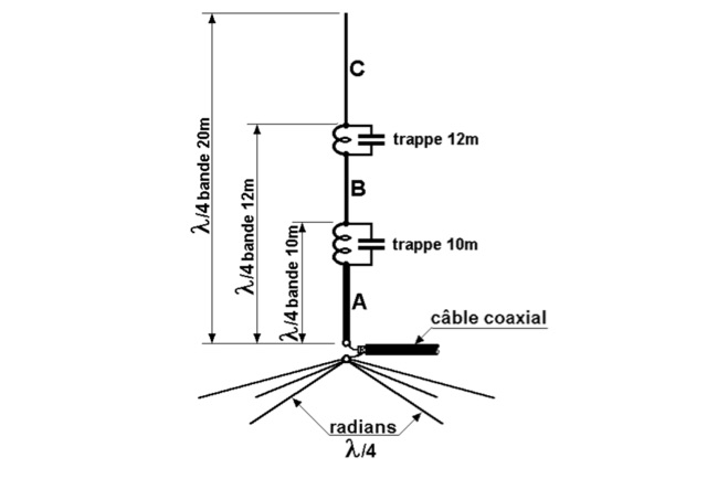 This antenna is an omnidirectional and multiband and it is well suited for DX enthusiasts with limited space. Each of the parallel circuits (trap) behaves like an isolator on its resonant frequency.
 -
 A light and sturdy Quad for 10 and 15 meters. Basic Quad antenna design considerations. Building and assembling a dual band HF QUAD antenna, designing and joining cross-arms and boom, assembling spreader and element wire installation notes. QST article.
 -
 A portable wire antenna for the HF bands, made with a common speaker wire. In its natural form, the speaker wire acts as parallel feed line coming up to the bottom of the PVC feed point. From there, it's split into two wires, one heading out each side of the PVC tee.
 -
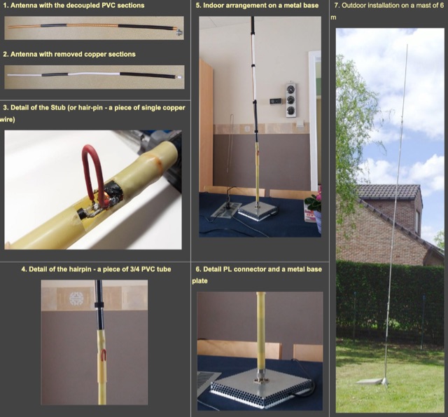 A travel, or a fixed vertical coax antenna originally designed by PA0FBK. This antenna is very easy to make from a piece of 50 ohm or 75 ohm coaxial cable, and can be either smooth, roll-up version, or rigid cable
 -
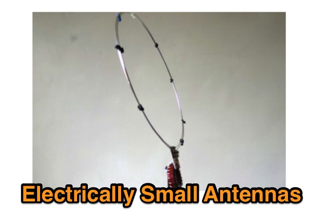 An antenna system is electrically small if it's enclosing sphere is <λ/2π. So a 10m band antenna of under 1.6m long qualifies.
 -
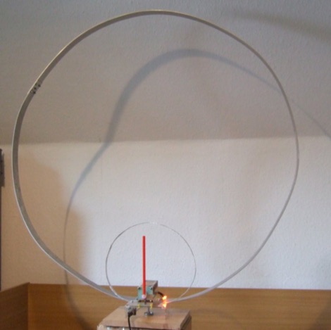
 In this article the author shows the receiving loop antenna for 160 meters band installed at his QTH. Diagram and movie available. Article in in Turkish but can be translated in english
 -
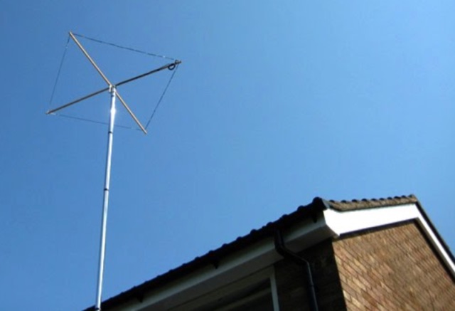 The Homebase-10 is a wire halo antenna for 10m built with DIY store parts, effective despite its small size. Includes a dual-band version for 10m and 6m with gain around 0 to -2dBd, near omnidirectional pattern, and horizontal polarization. Overview based on a 2008 Practical Wireless article.
 -
 The **LDG Z100 Autotuner** review by GW6ITJ details the unit's practical application and performance in a ham shack environment. Initially acquired to replace an MFJ-902, the Z100 is noted for its ease of use, though the author observes it doesn't quite match the impedance range of the older MFJ unit. This hands-on assessment provides a real-world perspective on its capabilities for 100-watt operation across the HF bands. GW6ITJ specifically mentions the Z100's suitability for 3.5 MHz and higher frequencies, indicating its utility for common HF operations. The review focuses on user experience rather than technical specifications, directing readers to the LDG website for detailed data and manuals. This approach highlights the tuner's operational characteristics from a user's perspective. The author's experience with the Z100 suggests it's a reliable choice for general amateur radio use, particularly for those seeking a straightforward autotuner. The comparison to the MFJ-902 offers a valuable benchmark for hams considering a similar upgrade or new acquisition, emphasizing practical differences in impedance matching.
 -
 A multi band antenna for HF band capable to operate from 10 to 80 meters band depending on wire lenght loaded with a small inductance neat the feed end.
 -
 Installation and assembly instructions for the multiband HF vertical Antenna by GAP
 -
 Details Amphenol's extensive product line, encompassing electrical, electronic, and fiber optic connectors, alongside coaxial and flat-ribbon cable solutions. The company designs, manufactures, and markets these interconnect systems globally, serving various communication network requirements. Their offerings support end-to-end connectivity, crucial for modern broadband infrastructure. Emphasizes the company's role as a major provider of components vital for reliable signal transmission in diverse applications. Products like _LMR(R) coaxial cables_ and various _RF connectors_ are essential for amateur radio installations, ensuring low loss and robust connections for antennas and transceivers. The focus on high-performance interconnects directly benefits hams constructing or upgrading their stations. Amphenol's broad portfolio includes specialized connectors and cable assemblies, meeting rigorous technical specifications for both commercial and amateur radio use.
 -
 This simple antenna was installed on the attic. Antenna was matched with help an Automatic ATU in 40, 30, 20, 17, 15, 12 and 10 meter amateur Bands. The Antenna worked satisfactory on the above mentioned bands.
 -
 Amateur Television (ATV) operations involve transmitting and receiving live or recorded video and audio signals over amateur radio frequencies. Unlike narrow-band modes, ATV utilizes a wider bandwidth to convey video information, often requiring specialized transceivers, antennas, and signal processing equipment. This mode allows hams to share visual content, demonstrate projects, or conduct video conferences, typically on VHF, UHF, and microwave bands due to the bandwidth requirements. The SwissATV resource focuses on the technical aspects and community engagement surrounding ATV within Switzerland. It covers topics relevant to setting up ATV stations, understanding signal propagation at higher frequencies, and participating in local ATV activities. The site serves as a central point for Swiss ATV operators to exchange knowledge and coordinate transmissions, fostering the growth of this specialized amateur radio mode.
 -
 Presents _Beam Quest_, the official Japanese distributor for _SteppIR_ antennas, detailing their product lineup and services. The site showcases various _SteppIR_ Yagi models, including the _Dream Beam_ series (DB42, DB36, DB18E, DB11) with configurations from two to four elements, alongside the _Big IR_ and _Small IR_ vertical antennas. It also lists accessories such as TX/RX and PC interfaces, essential for integrating these advanced antenna systems into a ham shack. Operators often seek out _SteppIR_ antennas for their dynamically adjustable element lengths, which allow for optimization across multiple bands, a significant advantage for DXing and contesting. This adaptability contrasts sharply with fixed-element Yagis, providing a distinct edge in varying band conditions. The resource provides contact information, including email and phone numbers, for inquiries and support regarding _SteppIR_ products within Japan, serving as a direct point of contact for sales and technical assistance.
 -
 Sixty-meter repeaters typically use a 1 MHz frequency separation between input and output, while 2-meter repeaters commonly employ a **600 kHz** split and 70-centimeter repeaters use a **5 MHz** offset. This article details the fundamental technical principles of amateur voice repeaters, explaining how they extend VHF/UHF communication range by receiving on one frequency and simultaneously retransmitting on another. It covers essential components such as receivers, transmitters, filters, and antennas, often situated on elevated locations for optimal coverage. The resource delves into the critical challenge of _desensing_—where the repeater's strong transmit signal overpowers its own receiver—and the engineering solutions employed, including antenna separation and the use of high-Q cavity filters. It also explores various control and timing systems, from basic squelch activation to more sophisticated microcontroller-based boards that manage functions like voice identification, time-out timers, and fault protection. Different access methods are discussed, including open access, toneburst, CTCSS subtone, and DTMF, each offering distinct advantages for managing repeater usage and mitigating interference. Furthermore, the article examines repeater linking, both conventional RF methods and modern internet-based solutions, highlighting how linking expands coverage and promotes activity across multiple repeaters or bands. It introduces less common repeater types such as 'parrot' repeaters, which use a single frequency and digital voice recording, and linear translators, capable of relaying multiple signals and modes simultaneously across different bands, often found in amateur satellites.
 -
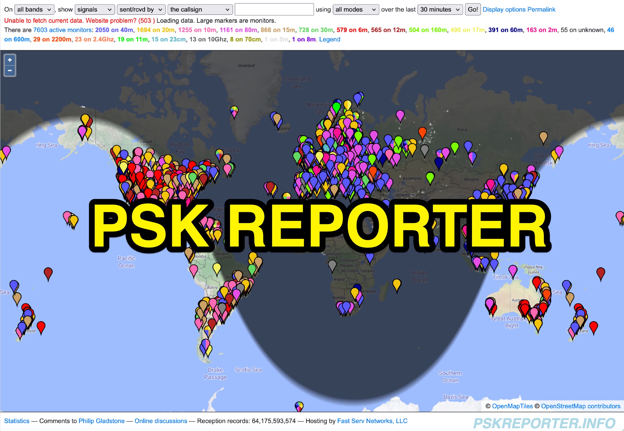 PSK Reporter provides a real-time visualization of amateur radio digital mode reception reports, aggregating data from a global network of monitoring stations. This platform is particularly useful for operators utilizing modes such as FT8, FT4, and PSK, allowing them to observe signal propagation paths and assess their station's reach. The interactive maps display reception reports, enabling hams to analyze band conditions and optimize antenna performance for various frequencies and times of day, aiding in understanding ionospheric conditions. Operators can filter reports by callsign, band, mode, and time, gaining insights into specific propagation events or evaluating the effectiveness of their transmit setup. The data collected helps in predicting optimal operating windows for DX contacts across various digital modes. Philip Gladstone is the contact person for comments and discussions regarding the system.
 -
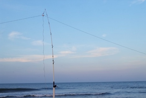
 A home made portable vertical antenna, that with a single 1/4 wave counterpoise wire is possible to achieve less than 1.5:1 SWR on 40, 30, and 20 meter bands. It is basically a center load, shortened ground plain vertical antenna.
 -
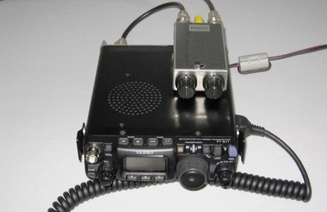
 Working from a small apartment-balcony on all bands with a small antenna
 -
 Sort of similar to the one of the 6m omni. Instead of using twin-lead, this design makes use of a more or less regular double bazooka antenna (coaxial dipole). Your attention shall be drawn to the available standart literature, such as Rothammel. In order to "compute" the dimension, Karl Rothammel mentioned that the total length of the dipole shall be 95% of the free-space wavelength. The short-circuit bridges (closing the folded dipole) are to be placed at a distance-fraction being equal to the velocity factor of the coax cable used, which will be 66% using RG-58 or RG174.
 -
 Developing operational amateur radio equipment for the 134 GHz band presents significant technical challenges, particularly in frequency generation and stability. This resource details the construction of a 134 GHz system, outlining its architecture with separate transmit (Tx) and receive (Rx) modules, each employing a local oscillator (LO) and RF head units. The system utilizes a dual Flann 50 GHz lens-type horn antenna configuration for optimal signal coupling. The transmit path incorporates an LMX2541 synthesizer chip operating at approximately 2.8 GHz, referenced by a 10 MHz double-oven Morion OCXO for exceptional stability. This signal is multiplied through a series of stages (X4, then X2) to generate a 22.4 GHz signal, which subsequently drives a dual series diode multiplier to produce the final X6 signal for 134 GHz operation. The receive side features an anti-parallel diode mixer coupled to a 144 MHz transceiver via a preamplifier, ensuring effective downconversion. Operational mode is CW, achieved by keying a multiplier stage. The project includes images of the Tx and Rx head units and describes a successful 3.5 km test with G8ACE, demonstrating stable signal tones due to PLLs locked to OCXOs at both ends, confirming the system's robust performance.
 -
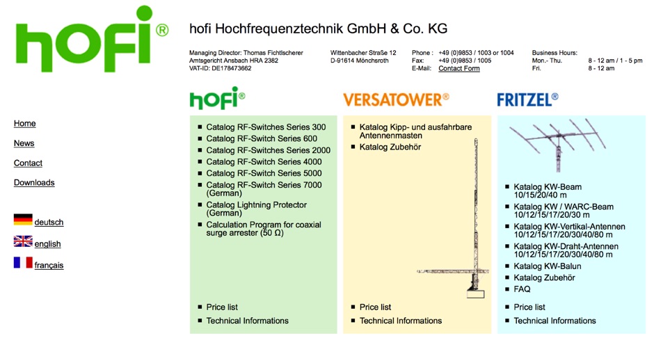 Showcasing innovative RF solutions, Hofi Hochfrequenztechnik manufactures high-quality _antennas_ and RF switches. Their products, including the **versatower** and **fritzel** brands, cater to both casual operators and serious DXers. With a commitment to performance, Hofi's offerings enable operators to achieve optimal signal gain and reliability in various conditions. The company's expertise in antenna design ensures that users can effectively communicate across _HF_ bands, enhancing their overall operating experience. Whether setting up a new station or upgrading existing equipment, Hofi provides essential tools for successful ham radio operations.
 -
 Designing and constructing a two-element receiving loop antenna array for HF operation involves specific considerations for achieving high directivity and noise reduction. This resource details a homebrew system comprising two 30-inch diamond-shaped loops, spaced 20 feet apart, which are fed through mast-mounted preamplifiers and passive signal combiners. The operational principle relies on adjusting phase delays between elements via precise _Belden 8241_ coaxial cable lengths, optimized for specific bands from 160m to 20m. Performance data, derived from _EZ-NEC_ modeling, illustrates consistent 90° azimuth-plane beamwidth and low take-off angles across the target bands, with _Receiving Directivity Factor_ (RDF) values comparable to a 300-foot Beverage antenna. The article presents detailed elevation and azimuth plots for 20m, 30m, 40m, 80m, and 160m, demonstrating the array's ability to provide strong response at low DX angles while also supporting _NVIS_ signals. Key components like the _DX Engineering RPA-1_ preamplifier and _DXE RSC-2_ signal combiner are discussed, alongside the importance of impedance matching to preserve antenna patterns. The construction emphasizes self-contained elements that do not require ground radials, offering a compact solution suitable for suburban environments and stealth installations, with a focus on optimizing receive performance independently from transmit antennas.
 -
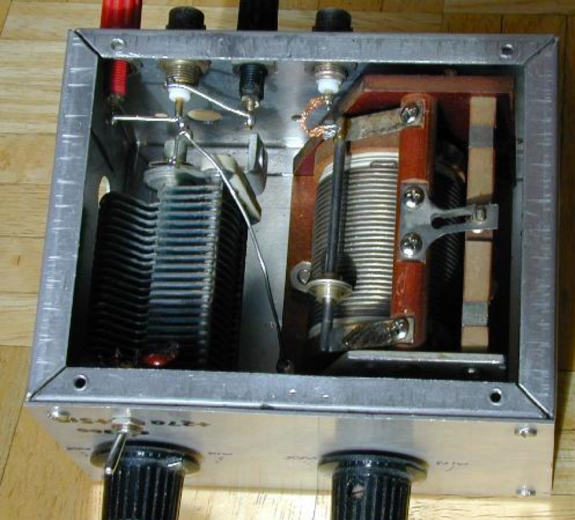
 A home made magnetic loop for HF Bands. This small and compact loop is designed to support small power transmissions on HF bands, from 7 MHz to 21 MHz
 -
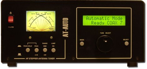 _AT Auto_ is an automatic antenna tuner designed for amateur radio enthusiasts seeking efficient and reliable tuning solutions. This device automates the tuning process, allowing operators to focus on communication rather than manual adjustments. The tuner is compatible with a range of transceivers, enhancing its versatility in different shack setups. Its design incorporates advanced circuitry to ensure optimal performance across various bands. The _AT Auto_ tuner is particularly useful for those operating in HF bands, providing seamless transitions between frequencies. Its integration capabilities with other shack automation products make it a valuable component for modern amateur radio stations. The tuner supports multiple modes, including _SSB_ and _CW_, catering to diverse operating preferences. Its robust construction and user-friendly interface contribute to its appeal among both seasoned operators and those new to the hobby. Kessler Engineering's focus on innovation and quality is evident in the _AT Auto_'s design. The tuner is part of a broader product line that includes shack automation solutions, reflecting the company's commitment to enhancing amateur radio operations. Despite the website redesign, the tuner remains a key offering in their product portfolio.
 -
 Constructing an End-Fed Half-Wave (EFHW) antenna offers a practical solution for HF operators seeking a multiband wire antenna without the need for extensive radial systems. This design typically employs a high-impedance transformer at the feed point, matching the antenna's inherent high impedance to a 50-ohm coaxial feedline. The article specifically details a 2012 approach, focusing on a transformer with a 49:1 turns ratio, which is a common configuration for EFHW antennas. The resource outlines the construction of a wire element cut for a half-wavelength on the lowest desired band, with specific coil arrangements enabling operation on harmonically related bands such as 40m, 20m, and 10m. It discusses the physical dimensions and winding details for the matching transformer, often utilizing a ferrite toroid core to achieve the necessary impedance transformation. The content provides insights into the operational principles and practical considerations for deploying such an antenna, including methods for tuning and optimizing performance across multiple amateur radio bands. While acknowledging that the presented information from 2012 may be superseded by newer insights, it serves as a foundational reference for understanding EFHW antenna theory and construction.
 -
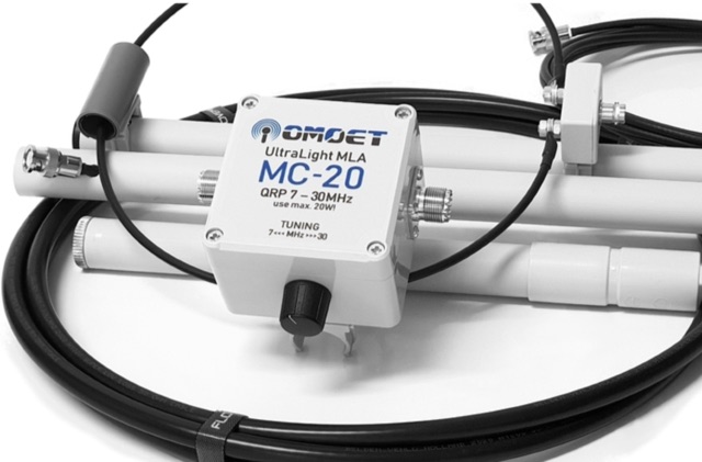 Maker of small and compact multiband QRP UltraLight Magnetic Loop Antennas and UnUn transformer for end-fed multiband antennas
 -
 A multi-band off centre fed dipole, designed to operate on all bands from 40m (7MHz) to 6m (50MHz). Author claims it will operate on 40, 30, 20, 17, 15, 12 and 10m without an ATU (SWR <3:1) plus 6m with an ATU.
 -
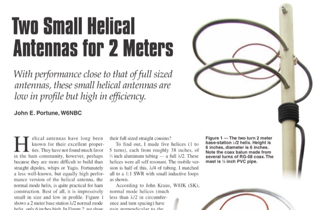 This article is about two excellent small helical antennas for the two meters band. With performance close to that of full sized antennas, these small helical antennas are low in profile but high in efficiency.
 -
 The ZS1J/B beacon operates on 28.2025 MHz with 5 Watts output to a half-wave, end-fed vertical antenna, initially installed in 1977 as ZS5VHF near Durban. The 10-meter transmitter is a modified 23-channel CB radio, and the identification keyer uses a diode matrix unit with TTL ICs from the same era. After relocation to Plettenberg Bay in 1993, the beacon has been in continuous service, with additional QRP transmitters later installed for other bands. In 1994, a single-transistor, 80-meter, 0.5-watt QRP transmitter with a half-wave dipole was added on 3586 kHz, followed by a 160-meter, 0.5-watt unit on 1817 kHz. A 30-meter, 0.5-watt transmitter was installed in 1996, operating on 10.124 MHz. In 2002, a 40-meter QRRP beacon on 7029 kHz, with an output of 100 microwatts, achieved DX reports up to 1100 km from ZS6UT in Pretoria. Best DX reports for the 80m and 160m beacons came from 9J2BO.
 -
 One of the featured products, the V350 CAMP, is a multiband vertical antenna covering 6 to 80 meters, priced at R$ 799,90, demonstrating the range of ready-to-use solutions available. The inventory includes various antenna types such as **HF**, **VHF**, and **UHF** designs, along with dual-band options like the J-Pole Dual V/UHF for R$ 235,00. For those building their own arrays, the store stocks essential components like element holders, clamps, junction boxes, and aluminum plates, alongside specialized items such as the KIT Isolador Central Dipolo - 01DX for R$ 99,90. The shop also provides a comprehensive selection of installation hardware, including diverse antenna mounts, PTT supports, and various coaxial cables like RG58 and RG213, with prices up to R$ 849,90 for RG213. Connectors such as UHF male PL259 and various adapters are readily available, ensuring compatibility for different setups. Additionally, specialized items like side handles for popular transceivers such as the FT857/891 and IC7300 are offered, catering to specific equipment needs. Beyond antennas, the store supplies practical accessories like transport bags, 12V power cables for transceivers, and even branded merchandise like the Antena Kit mug. Rodrigo Gonçalves, PP5BT, manages the operation from Blumenau, SC, Brazil, providing direct contact via WhatsApp at +55 47 9.9985.0155.
 -
 This is a antenna tuner with wide range tuning for antennas with a Z of + 50 Ohms on all the HF bands.
 -
 Low-frequency (LF) radio time signals, operating primarily in the 40–80 kHz range, are broadcast by national physics laboratories for precise clock synchronization. Transmitters like **JJY** (40 kHz, 50 kW; 60 kHz, 50 kW), RTZ (50 kHz, 10 kW ERP), MSF (60 kHz, 15 kW ERP), WWVB (60 kHz, 50 kW ERP), RBU (66.66 kHz, 10 kW), and DCF77 (77.5 kHz, 50 kW) cover vast geographic areas, often several hundred to thousands of kilometers. LF signals offer distinct propagation advantages over higher-band transmissions such as GPS. Their long wavelengths (3–6 km) enable effective diffraction around obstacles like mountains and buildings. The ionosphere and ground act as a waveguide, eliminating the need for line-of-sight and allowing a single powerful station to cover extensive regions. Ground wave propagation minimizes ionospheric variability effects on transmission delay, and signals penetrate most building walls effectively. Robust and low-cost receivers, often priced at 20–30 USD/EUR, are widely used in radio clocks. These receivers typically comprise a tuned ferrite core antenna, a receiver IC (e.g., Atmel T4227, U4223B, MAS1016) for amplification and AM detection, and a microcontroller for decoding the time signal and phase-locking a local clock. Specific components for DCF77, MSF, and WWVB are readily available from vendors like HKW Elektronik and Ultralink.
 -
 AN-SOF is a professional comprehensive software tool for the modeling and simulation of antenna systems. AS-SOF allows to describe antenna geometry, Choose construction materials, Describe the environment and ground conditions, Describe the antenna height above ground, Analize radiation pattern and front-to-back ratio, Plot directivity and gain, Analize input impedance and VSWR,Predict antenna bandwidth
 -
 How to build a limited space 10 and 20 meter band Square Halo DX antenna. A horizontally polarized antenna for 10 and 20 meter band, which is suitable for a limited space.
 -
 A 20-meter window frame stealth antenna, based on a design by _PD7MAA_, utilizes a single 620cm wire loop for discreet installation. The feeding mechanism employs a _4C65_ toroidal core, where the antenna loop functions as a single-turn secondary, and the feedline wraps twice. Tuning is achieved via a 30cm twisted wire stub, allowing for SWR adjustment within the 20m band. This design is specified for QRP operation, with a maximum power limit of **25 Watts** to prevent core saturation or arcing. Wire selection recommendations include thin, insulated copper wire (0.75mm to 1mm) for blending with architectural elements. The guide focuses on practical construction steps for a low-profile 14MHz antenna.
 -
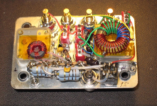
 This is a project aboout compact and portable a QRP antenna tuner for use in the HF ham radio bands from 3-30 MHz, even if it's a compact and efficient project this small antenna tuner will not match any possible load.
 -
 Thsi article describes a microcontroller driven semi-automatic antenna tuner capable of handling power levels up to 150 watts. The device is a low pass filter tuner manually tuned by setting the optimized L/C combination by hand and then storing the values into the EEPROM of the mictrocontroller to recall them later (seperately for each band from 80 to 10 meters including WARC bands)
 -
 The Buddistick antenna, as demonstrated by KP4MD, effectively handles up to **250 watts** and provides coverage from 40 through 10 meters, with an optional coil extending operation to 80 and 60 meters. KP4MD's video presentation meticulously describes the antenna setup, emphasizing the critical role of the _shunting coil_ for achieving resonance on lower bands like 40 and 80 meters. This practical approach highlights how a compact antenna can deliver solid performance from a constrained location. SWR curve diagrams are included, clearly illustrating the impact of the shunting coil on the antenna's resonating frequency. These visual aids provide concrete evidence of the adjustments needed for optimal operation across different bands, particularly when space is at a premium. KP4MD's insights are particularly valuable for hams operating from apartments or other limited spaces, showcasing real-world results from a balcony installation.
 -
 This is a detailed, technical piece, intended mostly for makers and more creative activators, who enjoy building and using their own tools on the summits. A multiband portable antenna tuner supporting 10W, small and light, suitable for SOTA operations
 -
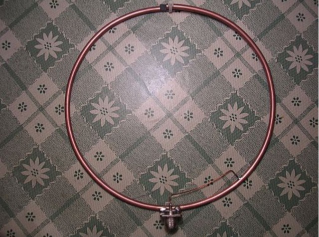 A small, easy to build, copper tube magnetic loop antenna for the 2 meters band. In Italian
 -
 This article presents an innovative homebrew antenna design utilizing surplus ladder line as a receiving antenna for HF and MF bands. The Ladder Line Antenna (LLA) transforms standard 450-ohm ladder line into a directional, bidirectional, or omnidirectional antenna system through different termination methods. The design, which requires minimal space and height, achieves 6-10dB front-to-back ratio on 40-160m bands using a 33-foot length. This DIY wire antenna project offers an efficient, low-profile solution for amateur radio operators, featuring broadband operation without ground radials and easy installation below fence height.
 -
 This page describes a comparison study on seven different beam antennas for 40 meters band. Yagi antennas, moxon antennas, mini horse all antennas are described with schema diagram , azimuth plot and SWR F/B Gain diagram