Search results
Query: Frequency
Links: 713 | Categories: 31
Categories
- Ham Radio > Band Plans > Frequency coordination
- Manufacturers > Test Equipment > Frequency Counter
- Technical Reference > Frequency Counter
- Software > Low Frequency
- Technical Reference > Radio Frequency Interference
- Manufacturers > Antenna Analyzers
- Technical Reference > Calculators
- Software > Databases
- Technical Reference > DTMF
- Technical Reference > Duplexers
- Radio Equipment > HF Transceivers > Elecraft K3
- Manufacturers > Antennas > VHF UHF Microwave > Ground Plane Antennas
- Operating Modes > HF Operations
- Propagation > MUF Indicators
- Radio Scanning > Nature
- Technical Reference > Radio Frequency Interference > Noise Reduction
- Radio Scanning > Police Scanning
- Radio Scanning
- Radio Scanning > Radio Scanning Reference
- Operating Aids > Radio Spectrum
- Radio Scanning > RailRoad
- Ham Radio > Resources
- Technical Reference > RF Design
- Manufacturers > Antennas > VHF UHF Microwave > Satellite antennas
- Manufacturers > Test Equipment > Spectrum Analyzers
- Operating Modes > SSTV
- Propagation > Sunspots
- Shortwave Radio > SWL Resources
- Shortwave Radio > Broadcasters > Time Signal Radios
- Manufacturers > Software Defined Radio > Upconverters
-
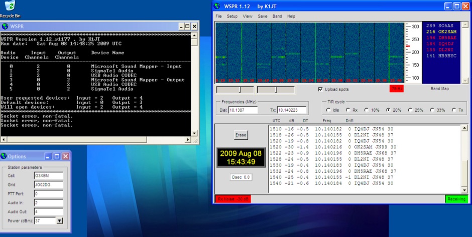 Introduction to WSPR beacons. Article describe WSPR2 and WSPR15 beaconing mode and include a frequency reference table for both WSPR modes
 -
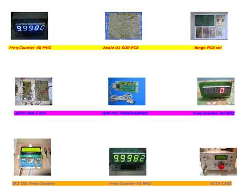 BITX ver 3 kits, frequency counters, SDR PCB, spare parts and relate ham radio accessories by VU3SUA
 -
 An overview of coax cable often called coaxial feeder or RF cable, used to feed antennas and deliver radio frequency power from one point to another
 -
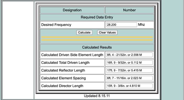 This calculator is designed to give the critical information of a particular beam antenna, in this case a three element Yagi, for the frequency chosen.
 -
 The TransWorld Antennas TW4040 The Adventurer Monobander™ is a portable HF antenna designed for rapid deployment in field operations, including **SOTA** and **POTA** activations. This manual details the antenna's assembly, tuning procedures, and operational guidelines for optimal performance on the 40-meter band. It outlines the specific components, such as the telescoping whip and base unit, required for proper setup. Instructions cover mast erection, radial wire deployment, and impedance matching to achieve a low **VSWR** across the designated frequency segment. The document also provides guidance on antenna orientation and environmental considerations for portable use. It specifies the antenna's power handling capabilities and physical dimensions when fully deployed and collapsed for transport.
 -
 Operating a ham station often involves encountering radio frequency interference (RFI), RF feedback, or RF burns, which are frequently misattributed to poor equipment grounding. This resource meticulously dissects these assumptions, asserting that RF grounds on the operating desk often merely mask more significant system flaws. It identifies five primary causes for RF problems, including antenna system design flaws, proximity of the antenna to the operating position, DC power supply ground loops, equipment design defects, and poorly installed connectors or defective cables. The content emphasizes that issues like "hot cabinets" or changes in SWR when connecting a ground indicate substantial RF flowing over wiring or cabinets, a phenomenon known as common-mode current. The article provides detailed explanations of common-mode current generation, particularly from single-wire fed antennas like longwires, random wires, and OCF dipoles, which inherently present high levels of RF in the shack. It also illustrates how vertical antennas, lacking a perfect ground system, can excite feed lines with significant common-mode current. Through simulations, the author demonstrates how a dipole without a proper _balun_ can cause RF problems at the operating desk, showing current patterns and voltage distributions on feed line shields. The discussion extends to the proper application of _RF isolators_ and _ferrite beads_, clarifying their role in modifying common-mode impedance on cable shields and cautioning against their use as a band-aid for fundamental system defects. The resource advocates for correcting the actual source of RF problems, such as antenna system issues or poor connector mounting, rather than relying on internal shack grounding or isolators. It highlights that properly functioning two-conductor feed lines, like coaxial or open-wire lines, should result in minimal RF levels at the operating position, even without a desk RF ground. The author shares personal experience, noting that his stations since the late 1970s have operated without RF grounds at the desks, relying instead on proper antenna system design and feed line integrity.
 -
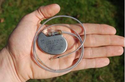 An ARRL article collection about influence of radio frequency with pacemakers and other similar medical devices.
 -
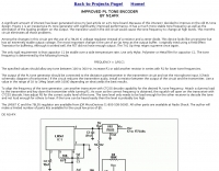
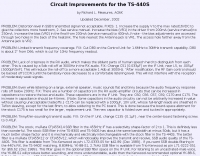 The page provides circuit improvements for the Kenwood TS-440S transceiver, addressing issues such as distortion in SSB signals, limited transmit frequency coverage, lack of crispness in RX audio, and flat audio response. The fixes include adjusting bias, cutting specific components, and changing capacitors to improve performance.
 -
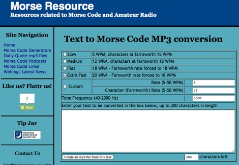 Convert any text in morse code mp3 file, you can choose speed from 5 to 50 wpm and tone frequency
 -
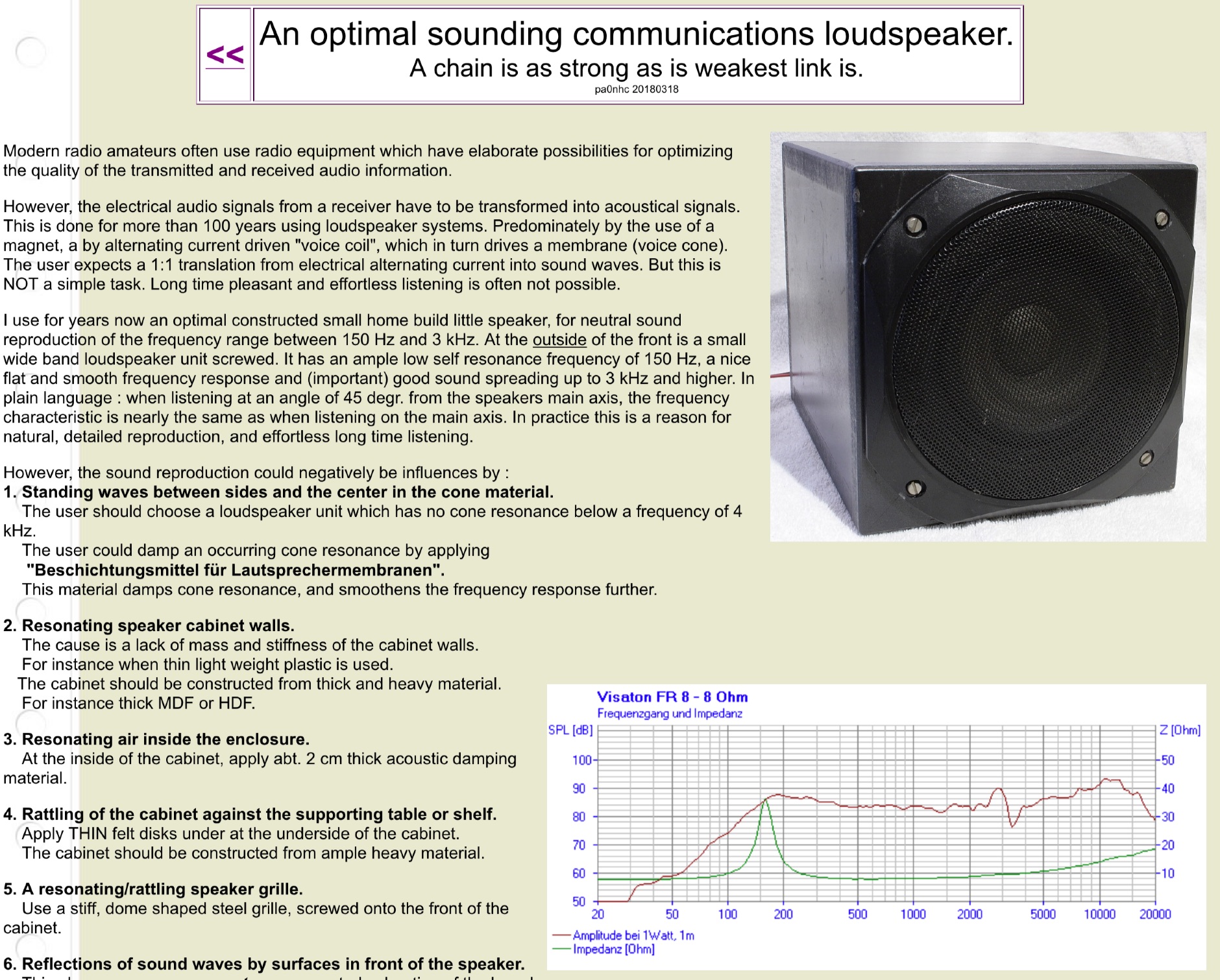 An interesting article on how build an optimal sounding communications loudspeaker capable to optimize sound reproduction at the frequency range from 150 Hz to 3 kHz.
 -
 Operating the AO-51 amateur radio satellite with a handheld transceiver (HT) presents a practical entry point for newcomers to satellite communications. This resource details the necessary steps and considerations for making basic contacts, focusing on accessible equipment. It covers fundamental concepts such as _Keplerian elements_ for satellite tracking and the importance of understanding Doppler shift effects on both uplink and downlink frequencies. The tutorial outlines a straightforward approach to satellite passes, emphasizing the use of readily available gear. It provides insights into antenna orientation and timing for successful two-way communication. The content aims to demystify satellite operation, enabling operators to achieve their first **AO-51** contacts with minimal specialized equipment. Key aspects include frequency management and basic operational techniques.
 -
 The resource provides coaxial cable attenuation data, listing signal loss in dB per 100 feet for various cable types across a frequency range from 1 MHz to 5.8 GHz. The initial table details attenuation for cables such as _RG-58_, _RG-8X_, and RG-213, with impedance values of 50 ohm or 75 ohm, at frequencies up to 1 GHz. For example, _RG-58_ exhibits **0.4 dB** loss at 1 MHz and **21.5 dB** loss at 1 GHz per 100 feet. A subsequent table expands on this data, including LMR series cables like _LMR-400_ and LMR-600, along with other types such as 9913F7 and RG214. This section covers frequencies from 30 MHz to 1,500 MHz, also noting the outer diameter of each cable. For instance, _LMR-400_ (0.405" diameter) shows **0.7 dB** loss at 30 MHz and 5.1 dB loss at 1,500 MHz per 100 feet. The final section focuses on VHF/UHF/Microwave amateur and ISM bands, presenting attenuation in dB per 100 feet (and meters) for frequencies including 144 MHz, 450 MHz, and 2.4 GHz. This table includes larger diameter hardline options like 1/2" LDF and 7/8" LDF, in addition to flexible coaxial cables. For example, 1/2" LDF cable demonstrates **0.85 dB** loss at 144 MHz and 6.6 dB loss at 2.4 GHz per 100 feet. DXZone Focus: Coaxial cable attenuation | LMR-400 | RG-58 | 5.8 GHz
 -
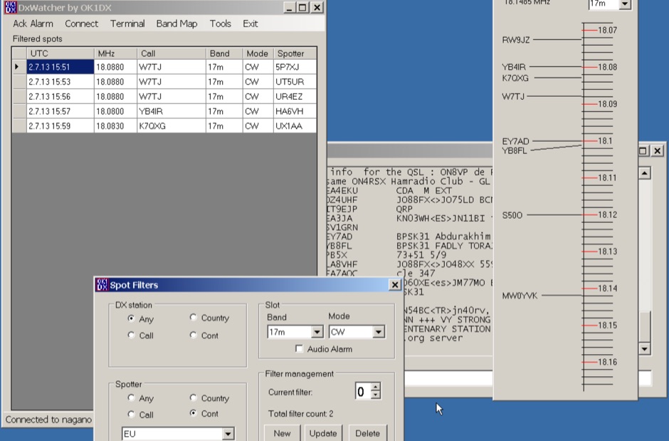 Demonstrates a specialized DX cluster monitoring application, _DxWatcher_, designed for Windows environments. It processes DX spots received via Telnet/Internet, presenting them in a filtered table and a dynamic bandmap. The software integrates with transceivers, specifically the FT-2000, to read VFO frequency and enable one-click tuning to spotted stations. _DxWatcher_ version 1.0.3.0, released on 13 June 2020, includes minor bugfixes and improvements such as enhanced recovery from suspend mode. Key features include configurable bandmap position and size, automatic opening, and bolding of spots received within the last **10 minutes**. The application utilizes the standard _ctry.dat_ file for DXCC country analysis, allowing users to update it for current DXCC status. Source code, developed in C# with MS Visual Studio 2008, is freely available, encouraging modification and sharing while requesting retention of the original author's callsign.
 -
 The 160-meter amateur radio band, spanning 1.8 to 2 MHz, was historically the lowest frequency amateur allocation until the introduction of the 630-meter and 2200-meter bands. ITU Region 1 allocates 1.81–2 MHz, while other regions use 1.8–2 MHz. This band, often called "Top Band" or "Gentleman's Band," was established by the International Radiotelegraph Conference in Washington, D.C., on October 4, 1927, with an initial allocation of 1.715–2 MHz. Effective operation on 160 meters presents significant challenges due to the large antenna sizes required; a quarter-wavelength monopole is over 130 feet, and horizontal dipoles need similar heights. Propagation is typically local during the day, but long-distance contacts are common at night, especially around sunrise and sunset, and during solar minimums. The band experienced a resurgence after the LORAN-A system was phased out in North America in December 1980, leading to the removal of power restrictions.
 -
 Digital multimeters, power supplies, frequency counters, RF analyzers, signal generators
 -
 Demonstrates the _RoMac Automatic CW Identifier 2012_ software, a Windows application designed to automate station identification and provide a tuning pulser. It can send CW identification via a sound card's audio output or by keying a radio's manual CW jack using a serial port's DTR line. The software also supports CAT commands for various Kenwood, Yaesu, Flex, and Elecraft radios, enabling automatic mode and frequency changes for ID transmission. It integrates with USB audio-capable radios like the Icom 7300 and Yaesu FT-991, simplifying connectivity with a single USB cable. The application features a fully programmable interface, adjustable CW speed from **5 to 35 WPM**, and ID intervals from **5 to 30 minutes**. The integrated "Pulse Tuner" function allows for safe amplifier and antenna tuner adjustments by sending short audio tones or rapid CW keying, with an adjustable duty cycle from 1% to 100%. It offers compatibility with a wide range of transceivers and amplifiers, and a schematic for a basic sound card interface is included for users without existing setups.
 -
 The BTech DMR-6X2 dual-band DMR handheld radio is thoroughly reviewed, detailing its features and performance for amateur radio operators. This resource covers the radio's capabilities for both VHF and UHF frequencies, supporting Tier II DMR digital and FM analog modes. It highlights key specifications such as its **136-174 MHz** and **400-480 MHz** frequency ranges, CTCSS/DCS, DTMF, 2-TONE, and 5-TONE signaling, and its _digital simplex repeater_ function. The review provides a comprehensive unboxing experience, listing included accessories like two Li-Ion batteries (2100 and 3100 mAh), a programming cable, and a 37-page English user guide. It also specifies the radio's physical dimensions of 5.1 x 2.4 x 1.5 inches and weights of 9.9 oz with the 2100 mAh battery and 10.8 oz with the 3100 mAh battery, offering practical insights for hams considering this transceiver.
 -
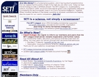 The SETI League, Inc., founded in 1994, focused on participatory science, developing technology to seek definitive answers to the question of extraterrestrial intelligence. The organization operated in five dozen countries across all seven continents, maintaining the quest for cosmic companions through the efforts of its 1500 members. Although the organization shuttered its virtual doors after thirty years in 2024, the website remains for educational and historical purposes, documenting past research and activities. Key technical resources include the _SETI League Mini-Manual_ for constructing a 12 GHz radio telescope under $200, and software like _SETIFox for Windows_ and _Radio Eyes_ for radio astronomy sky viewing. The site also features _Project Argus_ detections, moonbounce signal detections, and space probe signal detections, providing concrete examples of amateur radio astronomy applications. Publications such as the quarterly newsletter _SearchLites_ and various articles by Dr. SETI (H. Paul Shuch, Ph.D.) are available, alongside information on the Third Penn State SETI Symposium in 2025. The site also offers insights into hydrogen line emission observations, presented in time domain, frequency domain, waterfall, and surface plot formats.
 -
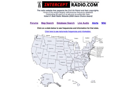 The radio website that respects the Civil Air Patrol and their copyrights. Home of the world's largest radio/scanner frequency database, include live police scanner recordings
 -
 T2FD is a 600-900 ohms folded dipole, terminated with resistor. Feed impedance is coupled with 50/600 ohms voltage balun. It is a wide band antenna with rather low SWR over the full designed frequency range: antenna tuner is seldom needed.
 -
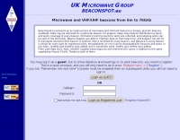 BeaconSpot.uk provides an accurate, real-time picture of microwave and VHF/UHF beacons operating across Europe, alongside a worldwide listing of 6-meter beacons. The platform allows users to retrieve detailed data for individual beacons, facilitating in-depth analysis of signal characteristics and propagation paths. Interactive maps visualize beacon distribution by frequency band and display spot coverage for each station, offering a clear geographical overview of active beacons. The system integrates real-time DXCluster spots, sourced from contributors like Alain, ON4KST, and Pascal, F5LEN, and enables users to submit outgoing spots directly to the DXCluster. Beacon keepers can manage their beacon data, receive email alerts upon being spotted, and track their station's ODX (Outstanding DX) records. For every received spot, the distance to the beacon is automatically calculated and displayed, aiding propagation studies.
 -
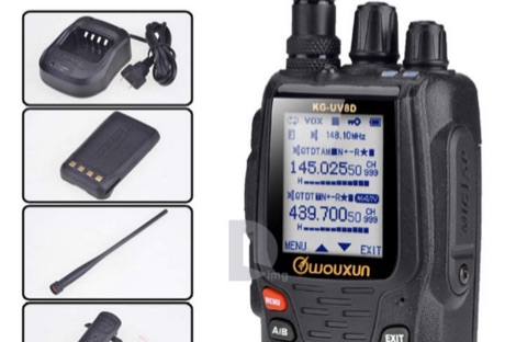 Wouxun KG-UV8D Standard Programming Software. Used to adjust or expand the frequency range to the full authorized range of the radio and not beyond. 134-174MHz 400-519MHz This software will Not add the 2.5kHz step.
 -
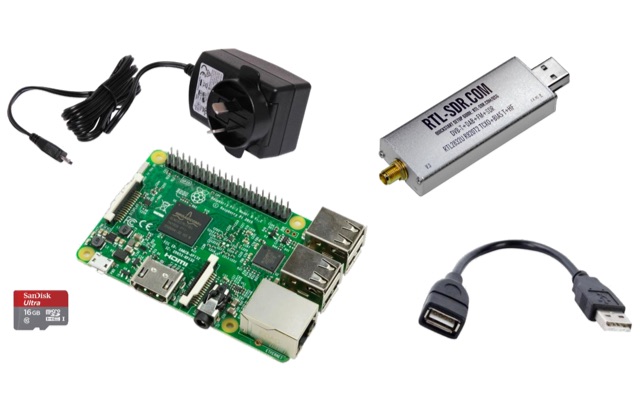 This project is a Software Defined Radio Receiver. It has a frequency range of 24MHz 1.2GHz. It can demodulate AM, FM, USB, LSB with selectable bandwidths of 600, 2400, 2800, 3200 and 6400Hz. Using a simple RTL-SDR Dongle and Raspberry Pi 3 computer using GNU RADIO
 -
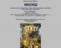 Experimental Longwave Transmissions from Tower Hill wayland Massachusetts Operator Name Warren, Ham Call K2ORS, Frequency: 137.7796 KHz
 -
 The article, "Using 75 Ohm CATV Coaxial Cable," details methods for employing readily available 75-ohm CATV hardline in standard 50-ohm amateur radio setups. It addresses the inherent impedance mismatch and practical considerations, such as connector compatibility, for hams seeking cost-effective, low-loss feedline solutions. The resource specifically contrasts common 50-ohm cables like RG-8, RG213, and _LMR-400_ with 75-ohm hardline, highlighting the latter's lower loss characteristics, particularly at VHF and UHF frequencies. It explores two primary approaches to manage the impedance difference: direct connection with an acceptable SWR compromise and precise impedance transformation. The direct connection method acknowledges that a perfect 1:1 SWR is not always critical, especially when using low-loss coax. For impedance transformation, the article explains the use of half-wavelength sections of coax to reflect the antenna's 50-ohm impedance back to the transmitter, noting its single-frequency effectiveness. It also briefly mentions transformer designs using toroid cores and a technique involving two 1/12 wavelength sections of feedline for broader bandwidth. The content further clarifies the concept of _velocity factor_ for calculating electrical versus physical cable lengths, providing a generic formula for precise length determination. It notes that while half-wave matching is practical for 10 meters and above, it can result in excessively long runs for lower bands like 160 meters, potentially adding **250 feet** of cable. The article also mentions achieving a usable bandwidth of 28.000 MHz up to at least **28.8 MHz** on 10 meters with specific transformation techniques.
 -
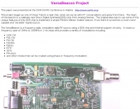 The VersaBeacon is a frequency agile, modulation agile RF source using a DDS chip and minimal support circuitry. It covers a frequency span of 1MHz to 150MHz in 1 Hz steps and provides a variety of modulations
 -
 W3HH wide-band wire antenna Article in French. The W3HH antenna, also known as the Terminated Folded Dipole (T2FD), is a compact, broadband antenna for amateur radio. It operates at an angle of 20 to 40 degrees and covers frequencies from 3 to 30 MHz. The antenna features a total length of one-third of the wavelength at its lowest frequency and is fed using a 1:4 BALUN transformer for impedance matching. A termination resistor around 390 Ω optimizes performance, making it suitable for various amateur radio applications while being easy to construct and install.
 -
 A synthesized 2.3 GHz Amateur Television (ATV) transmitter design, conceived by Ian G6TVJ, is presented, targeting broadcast-quality video performance on the 13cm band and extending up to 2.6 GHz. The core of the design utilizes a commercial Z-comm Voltage Controlled Oscillator (VCO) that tunes from 2.2-2.7 GHz, providing a +10 dBm output and simplifying RF alignment. This VCO's stability, originally intended for narrowband applications, readily accepts high-frequency video modulation, contributing to the transmitter's robust performance. The exciter stage, incorporating a Mini Circuits VNA 25 MMIC amplifier, boosts the signal to +16dBm, while a Plessey SP4982 prescaler divides the output frequency for the synthesizer. The synthesizer employs a Motorola MC145151 CMOS parallel IC, favored over the common Plessey SP5060 for its superior video modulation characteristics and ease of programming without microprocessors. This choice addresses issues like LF tilt and distorted field syncs often seen with SP5060 designs, particularly when operating through repeaters or over long distances. The MC145151 divides the signal further, enabling precise frequency stepping, with programming handled by EPROMs for channel selection and LED display. The loop filter network, critical for video integrity, was developed through experimentation to prevent the PLL from reacting to video modulation, ensuring a clean transmitted picture. The transmitter incorporates a Down East Microwave commercial power amplifier module, delivering approximately 1.6W output, driven by the exciter through a 3dB attenuator. Construction involves surface-mount SHF components on micro-strip lines etched onto double-sided fiberglass board, housed within a tinplate box. The design boasts no AC coupling in the video path, preserving low-frequency response, a common failing in other ATV transmitters. Performance tests with a 50Hz square wave revealed no LF distortion, and a calibrated "Pulse & Bar" signal showed a near 100% HF response, demonstrating its capability for high-quality ATV transmissions.
 -
 N1HFX project to improve PL tone encoder providing a more stable frequency
 -
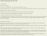 KC5M frequency measurement with yaesu ft-920
 -
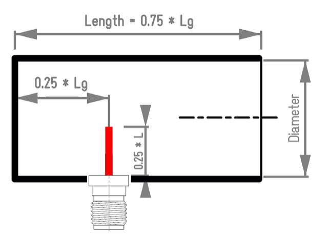 Aka Circular Waveguide Antenna. This online antenna calculator let you plan your cantenna for the desired frequency of operation, giving the Can diameter you have available.
 -
 A tutorial on using RF frequency counter, how a digital frequency counter works, includes frequency counter specifications and best practices in setting counter accuracy and resolution
 -
 Multi-frequency radio interferometers
 -
 Amplifiers, filters, attenuators, mixers, PLL, switches and frequency dividers, signal generators, power detectors, transimpedance amplifiers, variable gain amplifiers and more
 -
 SPX Communication Technologies, operating under the TCI International brand, presents a range of radio frequency (RF) solutions primarily for government, defense, and commercial sectors. The offerings include advanced systems for spectrum monitoring, communications intelligence (COMINT), and high-frequency (HF) and medium-frequency (MF) broadcasting and communication antenna systems. Specific product lines encompass _Blackbird_ COMINT systems, _Scout_ spectrum monitoring receivers, and various antenna arrays designed for robust performance in challenging RF environments. The resource details the capabilities of these systems, such as wideband signal detection, direction finding (DF), and signal analysis, crucial for intelligence gathering and regulatory compliance. It also highlights the engineering behind their antenna designs, which are optimized for specific frequency ranges and operational requirements, including high-power broadcast applications and secure military communications. The information presented emphasizes the integration of hardware and software for comprehensive RF situational awareness. The company's focus on empowering partners to "Command the Spectrum" underscores its commitment to delivering critical tools for signal interception, analysis, and management across diverse operational landscapes.
 -
 News, frequency guides and programme information, on shortwave and other international media.
 -
 W6CQZ JT65-HF project on sourceforge, the Amateur Radio software for reception/transmission of JT65A protocol with an emphasis upon its usage in the High Frequency Amateur Bands. Project is currently paused.
 -
 For over 50 years, Communications Specialists Inc. has been a cornerstone in specialized radio frequency solutions, initially gaining prominence with their **CTCSS** and **DTMF** tone signaling products widely used in amateur radio repeaters and commercial two-way radio systems. My own experience with their tone boards in various repeater builds confirms their reliability and ease of integration, a testament to their engineering. The company's legacy in tone encoding and decoding is well-established, providing robust solutions for access control and selective calling. Beyond tone signaling, Com-Spec has diversified into niche markets, including wildlife telemetry, pet tracking collars, and specialized tracking systems for model aircraft and rocketry. Their product line features compact transmitters and receivers designed for specific tracking applications, demonstrating a commitment to precision and durability in challenging environments. While some legacy products are no longer available, Com-Spec continues to innovate, as evidenced by the new R-30M receiver, which ships within five days. This focus on specialized RF applications, from tracking Alzheimer's patients to law enforcement, highlights their unique position in the radio communications industry.
 -
 100-watt UHF repeater (444.500+ PL100) and a 6-meter repeater (53.68- PL114.8) are owned and maintained by South County ARES to support emergency communications for Belmont, East Palo Alto, Foster City, Menlo Park/Atherton, Redwood City, San Carlos, San Mateo, and Woodside/Portola Valley. The organization emphasizes training, including weekly nets and practice sessions, to improve message passing accuracy and brevity, crucial skills for **emergency communication**. Resources like the San Mateo County Sheriff's Office Ham Radio Frequency Plan Recommendation and **Chirp-compatible CSV files** for Baofeng radios are provided. Participation in community events is encouraged to build skills and connections among members. The group operates without collecting dues, relying on donations and member contributions of time and expertise. Training pages are available for new hams and those seeking license upgrades, along with a "Tips for New Hams" section. The site also features a monthly calendar of events, including board meetings, general meetings, and hospital nets, alongside a newsletter, the "South County Communicator," and various operational documents like the Net Control Manual and SCARES Handbook.
 -
 SWR analysis of an Alpha-Delta DX-LB Plus antenna, configured as an inverted-V with the apex at 40 feet and ends at 15 feet, reveals specific performance characteristics across the HF spectrum. Measurements were conducted using a RigExpert AA54 antenna analyzer, scanning from 0.100 MHz to 54.000 MHz to capture full-range SWR plots. The antenna exhibits notably narrow bandwidths on 80 meters and 160 meters, attributed to its loading coils, necessitating precise tuning for optimal operation within these bands. Conversely, the Alpha-Delta DX-LB Plus demonstrates excellent SWR across the entire 40-meter band, indicating a broad resonance. Performance on 10 meters also shows favorable SWR, though tuning to a desired operating frequency is still recommended for peak efficiency. The article details the methodology and tools employed, building upon a previous "Part 1" analysis of a G5RV antenna, providing a comparative context for antenna evaluation. Practical experience with this multi-band antenna, particularly its loading coil design, highlights the challenges in achieving desired SWR across all bands without specific adjustments. The author's subsequent plans involve replacing the Alpha-Delta DX-LB Plus with a homebrewed 80-40-20-10m parallel **fan-dipole**, aiming for improved resonant characteristics.
 -
 The New England Historical Radio Society Inc. is an organization dedicated to the preservation of commercial Morse Radiotelegraphy on medium and high frequency.
 -
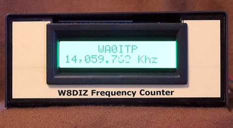 This Frequency Counter Development Kit is fully functional with the included pre-programmed microprocessor
 -
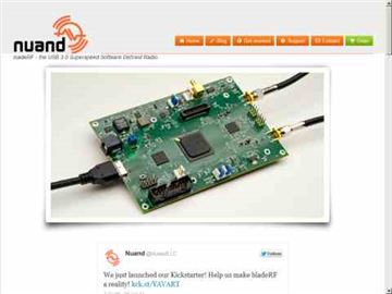 Nuand id the maker of bladeRF - the USB 3.0 Superspeed Software Defined Radio, 300MHz - 3.8GHz RF frequency range Independent RX/TX 12-bit 40MSPS quadrature sampling
 -
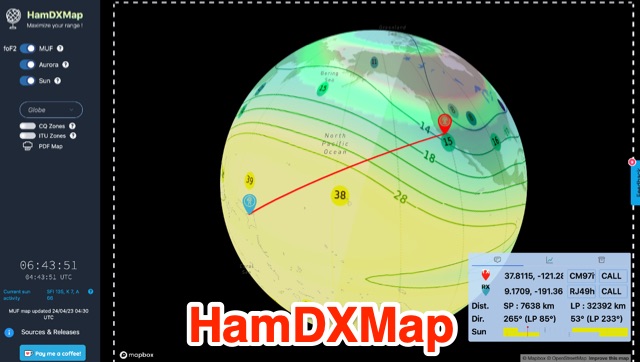 This dynamic DX Map aggregates various resources that will help radio amateurs to operate their stations in search of long distance contacts, DX. HamDXMap displays current MUF values and foF2 critical frequency values around the globe.
 -
 Demonstrates the complete design and development process for a **Low Noise Microwave Amplifier** (LNA), beginning with conceptual design and progressing through prototyping. The tutorial series covers the initial stages of a single-ended first gain stage, focusing on critical parameters such as noise figure, gain, and stability. It systematically details the theoretical underpinnings and practical considerations for achieving optimal performance in microwave frequency applications. This resource provides a structured approach to LNA construction, enabling radio amateurs and RF engineers to understand the iterative steps involved in realizing high-performance receive-side amplification. It offers insights into component selection, impedance matching networks, and the measurement techniques required to validate design specifications, particularly for **microwave** band operation where noise performance is paramount.
 -
 MorseExpert 1.15 decodes Morse Code audio to text, leveraging algorithms from CW Skimmer for optimal performance on weak, fading signals amidst interference on amateur radio bands. It processes audio from the device's built-in microphone or an external radio receiver via cable, optionally highlighting Ham callsigns and keywords. The application features a waterfall display with a bandwidth of 200-1200 Hz, decodes frequencies between 300-1100 Hz, and supports keying speeds from 12-45 WPM with automatic CW pitch detection. Recent updates include support for Android 15, edge-to-edge mode, improved stability, and a pause decoding button. A premium version offers an ad-free experience and user-selected text colors. Users can switch between General Text mode and Ham Radio QSO mode, which enhances word segmentation and highlights callsigns. The app also includes a frequency lock mode, text selection capabilities for copying, sharing, or saving decoded text, and provides guidance on reducing acoustic echo and constructing an audio attenuator for optimal radio interfacing.
 -
 Inches and meters Javascript Wavelength Calculator allow to input a frequency in MHz and calculate wavelenght in several units considering also fractions of wavelenght and the velocity factor. Includes an usefull inch to meter converter
 -
 FMI provides superior solutions in the design and manufacture of frequency control devices including Voltage Controlled Temperature Compensated Crystal Oscillators (VCTCXO), voltage controlled crystal oscillator (VCXO), Temperature Compensated Crystal Oscillators (TCXO), crystal clock oscillators, high temperature oscillators, surface mount and crystal oscillator products, phase locked sources and more.
 -
 Transferring Radio Frequency Energy from Your Transmitter to Your Antenna by Don Keith N4KC
 -
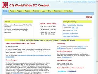 The CQ World Wide DX Contest records page details the highest scores achieved in the CQ WW DX Contest across various categories and years. It systematically lists records for both SSB and CW modes, segmenting results by entry class such as Multi-Multi, Multi-Two, Multi-Single High, Multi-Single Low, Single Operator High Power, Single Operator Low Power, Single Operator QRP, Single Operator Assisted High, Single Operator Assisted Low, and Single Operator Assisted QRP. Each record entry specifies the callsign, the operator's callsign in parentheses if different, the year of operation, and the total score achieved. The data is further broken down by individual amateur radio bands, including 160m, 80m, 40m, 20m, 15m, and 10m, allowing for granular analysis of performance within specific frequency segments. The page also includes records for the "ALL" band category, representing cumulative scores across all operational bands. The presented records span from 1948 to 2025, providing a historical perspective on contest performance. This resource also references other CQ contests like CQ WPX, CQ WW RTTY, CQ WPX RTTY, CQ 160, CQ VHF, and WW DIGI, indicating a broader context of contest record keeping. It explicitly states that late logs are not included in the records, ensuring data integrity. The page is maintained by the World Wide Radio Operators Foundation, Inc.