Search results
Query: antenna rope
Links: 160 | Categories: 2
-
 Demonstrates the construction of a **multi-band HF mobile antenna** utilizing a modified CB whip antenna base. The resource details the process of stripping a commercial CB whip, winding a new helical coil with 0.7mm insulated copper wire, and identifying tapping points for various HF bands. It emphasizes the importance of a rugged, slim design for mobile operation, discussing mechanical length, power handling (up to 200 watts), and coil diameter considerations. The article includes a graphic illustrating the antenna's operational principle, where sections of the helical coil are shorted from bottom to top to maintain efficiency and high Q. The resource presents a practical approach to achieving **band switching** without an external tuner, by manually adjusting tapping points on the coil. It provides a table with reference lengths in centimeters from the feedpoint for 7 MHz (40m) through 28.7 MHz (10m), including WARC bands. The author details mounting techniques, suggesting a Diamond bracket for secure attachment to a vehicle trunk, and stresses the critical role of proper grounding for optimal performance. The design allows for operation on 75m and 80m bands by adding a 110mm steel whip.
 -
 A 10-20 meters coverage delta loop antenna. After relocating, DL2HCB designed a multiband loop antenna to cover 10-20m with an open-wire feed for impedance matching and compact installation. Inspired by the mini-X-Q design, a modified 10m delta-loop was built, enhanced with a 1/4 wave shorted stub for 28 MHz using 450-ohm ladder line. The antenna delivers east-west broadside radiation and performs as a closed loop on other bands. Operational tests yielded strong European signals and successful DX contacts, including a 20m QRP QSO with FY/DJ0PJ.
 -
 The G5RV antenna, with an overall length of **31.10m (102ft)**, functions as a 3/2-wave on 20 meters when installed horizontally at 12m (39ft), exhibiting a resonant frequency of 14.150MHz and an approximate resistance of 80 ohms. Its 10.36m (34ft) stub line, designed as a 1/2-wave on 14.150MHz with a 0.97 velocity coefficient, acts as an impedance transformer across other bands, aiming for multiband operation without traps. On 20m and higher frequencies, the G5RV demonstrates improved gain compared to a standard dipole, attributed to the _collinear effect_ from multiple 1/2-waves along the wire. The original design sought a multiband solution for limited spaces, often requiring an Antenna Tuning Unit (ATU) for effective operation across bands like 80, 40, 30, and 20m, particularly with modern solid-state PAs. Variants, such as the F8CI modification, incorporate a 1/4 current balun at the stub line's base for symmetrical-to-asymmetrical transition, known as a _remote balun_. Proper flat-top or inverted-V installation is critical for maintaining symmetry and collinear gain, with inverted-V apex angles below 120° progressively diminishing higher-band performance.
 -
 This guide provides step-by-step instructions for constructing a tin can waveguide antenna, commonly known as a cantenna, for enhancing WiFi signal range. The project is budget-friendly, costing under $5, and utilizes easily accessible materials like a food can and basic electronic components. The design is suitable for 802.11b and 802.11g wireless networks, operating within the 2.4 GHz frequency range. To start, gather the necessary parts including an N-Female chassis mount connector, nuts, bolts, and a suitable can. The assembly process involves drilling holes in the can for the connector and mounting the probe. The guide emphasizes the importance of can dimensions and placement for optimal performance, encouraging experimentation for best results. This project is ideal for amateur radio operators and DIY enthusiasts looking to improve their wireless connectivity without significant investment. Safety precautions are advised, as the author does not hold electrical engineering credentials. Users are encouraged to take responsibility for their equipment and ensure proper assembly. With this simple yet effective antenna, users can extend their WiFi coverage and enjoy enhanced connectivity.
 -
 Cubic quad antennas are renowned for their high gain, excellent front-to-back ratios, and low angles of radiation, making them a popular choice among amateur radio operators. This resource provides detailed designs for constructing cubic quads optimized for 2, 6, 10, 12, and 15 meter bands. The lightweight structure can be easily built using fiberglass tubes and central hubs, allowing for portability and ease of assembly. The article discusses the specific dimensions and configurations required for both HF and VHF applications, emphasizing the importance of proper spreader lengths and boom dimensions. It also highlights the challenges of assembling larger cubic quads in limited spaces, offering practical solutions for hams with smaller backyards. With a focus on multi-band operation, this guide serves as a valuable resource for both novice and experienced operators looking to enhance their antenna systems.
 -
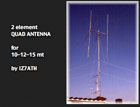 This resource provides comprehensive instructions for constructing a 2 element quad antenna specifically designed for the 10, 12, and 15 meter bands. The antenna features a diamond configuration, which offers improved gain compared to a square configuration. The author shares insights into the materials used, including a square-aluminum boom and bamboo poles, along with construction techniques that ensure durability and optimal performance. This project is ideal for amateur radio enthusiasts looking to create their own antennas at home. In addition to construction details, the author discusses the antenna's performance, noting its effectiveness even at a height of 8 meters. The quad antenna reportedly performs comparably to a 3 element yagi, with excellent SWR readings and strong signal reports from European stations. This project is suitable for beginners and offers a cost-effective solution for those interested in enhancing their amateur radio setup with a homemade antenna.
 -
 Details the construction of a **multiband vertical** antenna, specifically designed for stealth operation in a rented property, covering 80m, 60m, 40m, and 30m. The author, N3OX, leverages a 12m Spiderbeam telescoping fiberglass pole as the primary support, noting its sturdiness compared to typical fishing rods while remaining light enough for quick deployment and takedown. The radiating element is a 14 gauge Flex-Weave wire, attached to the pole's top with a rubber grommet, and fed by 27 bare 18 gauge radials spread across a 40-foot square backyard. N3OX describes the impedance matching solution, opting for custom-built L-networks over a remote tuner to enable fast bandswitching. Using an MFJ-259B and EZNEC modeling, base impedances were measured and component values calculated with G4FGQ's L_TUNER and SOLNOID_3 programs. The 80m coil is wound on a 3.5-inch PVC form, while the 30m, 40m, and 60m coils are air-wound, self-supporting #10 wire. Variable capacitors are incorporated for 40m and 30m shunt elements, with the 60m impedance matched by a series inductor. The project includes a **servo-controlled** homebrew band switch, utilizing a two-pole 12-position ceramic wafer switch for remote operation, addressing the limited 80m bandwidth. The entire matching network is housed in a weather-resistant shelter constructed from lumber and aluminum flashing. N3OX reports good DX results at 100W, estimating the total cost between $150 and $250, depending on existing parts.
 -
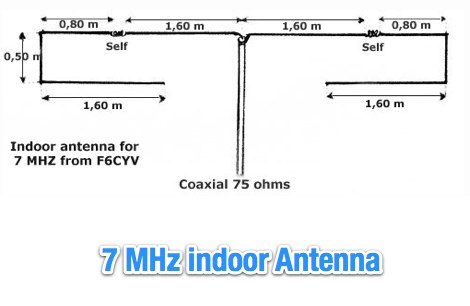 The page provides a project for an indoor wire antenna for the 7 MHz band, based on a design by F6CYV. It aims to help amateur radio operators lacking space to set up an antenna for 40 meters. The author shares their experience using the antenna inside an apartment, noting good reception of European signals and contacts with over 150 countries. The project details the materials and dimensions needed for the antenna, along with tips for optimal performance.
 -
 The 144-430 portable j-pole antenna is designed for amateur radio operators seeking a lightweight and efficient solution for VHF and UHF communications. This antenna is particularly useful for portable operations, allowing hams to set up quickly in various locations while maintaining excellent performance. Constructed from readily available materials, it can be easily homebrewed, making it an ideal project for both beginners and experienced operators alike. The j-pole design offers a simple yet effective configuration that provides a good match across the 144 MHz and 430 MHz bands. Its vertical polarization and omnidirectional radiation pattern make it suitable for local communications and simplex operations. This antenna can be deployed in various environments, whether in the field or at home, and is well-suited for mobile applications. With proper construction techniques, operators can achieve optimal performance, enhancing their ability to make contacts during contests or casual QSOs.
 -
 This antenna makes 80 and 160 enjoyable. Less than $50 to hear Europeans all summer on the LF bands seems like a good deal if you have the space!
 -
 Constructing a 2-meter 5/4 wave antenna, N1HFX details a design fully enclosed within 3/4-inch PVC tubing, addressing the significant velocity factor of PVC which necessitates a 19% reduction in physical length. The design incorporates a specific matching system using 300-ohm TV twin lead to counteract the highly inductive impedance component inherent in a 5/4 wave radiator. Key components include #18 stranded insulated wire for the radiating element, RG58/U coax, a PL259 connector, and a hardwood dowel for internal support, all carefully dimensioned for optimal performance within the PVC housing. The article provides precise cutting lengths for the twin lead and #18 wire, with the overall assembly measuring 77 3/4 inches, reflecting an approximate velocity factor of 0.81. Tuning instructions emphasize taking SWR readings with the antenna assembly inside the PVC, adjusting the #18 wire and twin lead in small increments to achieve a low SWR across the 2-meter band. The prototype antenna achieved SWR readings below 1.2:1 across the entire band, and N1HFX suggests an estimated 6 dB gain when properly mounted, offering a cost-effective alternative to commercial antennas.
 -
 Optimizing the impedance transformation and common-mode current suppression in antenna systems often involves selecting an appropriate balun. This project presents a **hybrid balun** design, combining characteristics of both voltage and current baluns to achieve superior performance, particularly when used with an antenna tuner. The design addresses issues like **common-mode current** on the feedline, which can distort the antenna's radiation pattern and introduce RFI in the shack. The construction details include winding techniques for the toroid core, component selection, and practical considerations for integration into an existing antenna system. Performance comparisons are drawn against conventional balun types, highlighting the hybrid balun's effectiveness across the HF bands. The resource provides insights into the current distribution and impedance matching properties, crucial for efficient power transfer and reduced SWR.
 -
 The HB9ABX RoomCap antenna document details the construction and performance characteristics of a compact HF antenna design. It presents a series of comparative field tests conducted between July and September 2005, evaluating the HB9ABX antenna against established designs like the Microvert MV-500, Cushcraft R5/R7000 verticals, and a 5-element DJ2UT Yagi beam. Specific test scenarios include mobile installations, rooftop deployments, and comparisons on 20m, 40m, 80m, and 160m bands, with signal reports from various European and DX stations. The resource emphasizes the antenna's small physical footprint and its claimed efficiency across multiple HF bands. Test results consistently show the HB9ABX antenna performing comparably to, and often outperforming, larger reference antennas in terms of received signal strength, with reported differences of 1 to 2 S-points (6-12 dB) in many contacts. Notably, a 20m DX test on July 26, 2005, indicated the 1.3m HB9ABX radiator yielded 2-3 S-points stronger signals than an R7000 vertical for US DX stations. An August 12, 2005, test on 40m highlighted the HB9ABX's superior signal-to-noise ratio in urban QRM, demonstrating 10-18 dB better performance than an R7000. The document includes specific callsigns, signal reports, and QTHs for each comparison, providing empirical data for the antenna's performance claims.
 -
 Installing your dipole end insulators, a beginner guide to proper setup wires to insultaors.
 -
 Details the construction and optimization of antenna systems for amateur radio satellite operations, focusing on practical, homebrew solutions for VHF/UHF bands. It covers building _groundplane antennas_ from salvaged materials, recycling old beam antennas into new configurations like a 2-meter crossed yagi, and constructing a 10-meter horizontal delta loop. The resource also explains antenna matching techniques, including folded dipole driven elements and quarter-wave transformers, along with the importance of accurate SWR measurements and minimizing coax loss. Demonstrates how to achieve a **1:1 SWR** by carefully trimming elements and adjusting radial angles on groundplane antennas. It provides insights into selecting appropriate coax and connectors, highlighting the benefits of Belden 9913 for low loss and the proper installation of _N-connectors_. The article also addresses RFI mitigation from computer birdies and presents a design for a silent triac antenna control circuit, offering practical solutions for common satellite station challenges.
 -
 Types of beverage wires, choose best supports and insulators, multiple antennas at one feedpoint, all well documented with photos and exaustive explanation. This article offers insights on building Beverage antennas for optimal reception. Key takeaways include using strong wire (copperweld or electric fence), proper termination, and a good grounding system (multiple copper rods). The author recommends maximizing antenna length and orienting it towards desired stations. For best results, utilize an antenna tuner and experiment with termination resistors.
 -
 Presents the KE4UYP linear-loaded vertical antenna design, which introduces very little loss on 80 or 160 meters, achieving an overall radiation efficiency of 80% to 85%. This design addresses common pitfalls of traditional base-fed verticals by placing the majority of the current at the top of the antenna, eliminating the heavy reliance on extensive ground radial systems. The author's initial 10-meter model, only three feet tall, yielded 5/9 signal reports to Anchorage, AK, and Europe, confirming its effectiveness. The antenna incorporates both vertically and horizontally polarized radiators, with a 1/4 wavelength horizontal counterpoise located at the feed-point, near the top, to create an almost totally omnidirectional pattern with high wave angle horizontally polarized radiation. This dual polarization ensures even illumination across all take-off angles, making it effective for both local contacts and **DXing**. The vertical element is linear loaded, adding capacitance reactance and making it longer than the horizontal element to achieve resonance and raise the feed-point impedance to 50 ohms. Fine-tuning the antenna requires careful adjustment, as tower reactance can vary. The article suggests starting with 80 feet for 80m and 170 feet for 160m for the vertical wire, then trimming for resonance. Bandwidth specifications include 300 kHz under 2:1 **SWR** on 80m and 100 kHz on 160m when suspended between trees, or 150 kHz on 80m when side-mounted on a tower.
 -
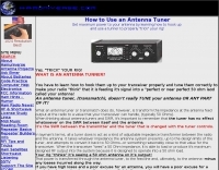 Get maximum power to your antenna by learning how to hook up and use a tunner to properly "trick" your rig
 -
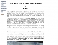 Building a directional antenna for limited space, M0MRR shares his experience constructing a 10-meter Moxon rectangle. Initially using fiberglass fishing poles and a plastic breadboard, he achieved a 1:1.2 SWR across the band with 50 watts, making contacts as far as PY2TO from the UK. The design incorporates 10-amp power cable for elements and RG58 coax with crocodile clips for feeding, demonstrating a cost-effective approach. His field observations confirm the directional properties, noting European signals fading when facing Stateside, and receiving better reports from stations in the antenna's favored direction. While not formally measured, the front-to-back ratio appears effective. The initial build was somewhat flimsy, intended for temporary deployment, but proved effective for DX. Later, M0MRR constructed a more robust 10-meter Moxon using tubular aluminum pipe, indicating an evolution in his design approach for durability. The project highlights practical antenna building for small backyards, emphasizing the benefits of a directional antenna even with modest power.
 -
 A **mobile HF multiband antenna** project details the construction of a center and top-loaded design, optimized for 10 through 80 meters. This antenna incorporates a capacity hat positioned high on the whip for enhanced efficiency, differing from commercial bugcatcher designs. The coil construction prioritizes high Q and minimal loss through an air core, open spacing, and heavy gauge wire, contributing to its lightweight nature and suitability for portable operation with a proper counterpoise. Band switching is achieved by manually moving a jumper plug to various tap points on the coil, allowing for operation across multiple bands, with 17m being resonant when the coil is bypassed. The design, a result of nine months of experimentation by N1LO, includes detailed instructions for modifying a Hamstick antenna base, creating a jumper wire, and assembling the capacity hat using stainless steel wire and silver-bearing solder for robust connections. The loading coil utilizes nylon grommet strips around a PVC pipe for an air-core winding, ensuring high efficiency. Tap sockets are fashioned from silver-plated 5-way binding posts, providing low-resistance RF joints for band selection. Guidance on tap point determination emphasizes using an antenna analyzer like the MFJ 259B or 269 to achieve resonance, especially on 40m and 80m where feedpoint resistance can be low. The document also covers the installation of monofilament stays to maintain antenna uprightness at highway speeds, with specific attachment points for stability.
 -
 This drawing shows a simple 10 meter wire J-pole antenna designed for 28.4 MHz. It is a vertical, end-fed Zepp-style antenna made from common materials and intended for easy home construction. The main radiating element is a straight length of stranded copper wire, either 14 or 18 gauge, cut to about 16.5 feet. At the top, the wire is supported by an insulator, allowing the antenna to be hoisted vertically. The matching section is made from 450-ohm ladder line, approximately 7 feet 9.5 inches long, and shorted at the bottom. This matching stub transforms the impedance so the antenna can be fed with coaxial cable. The feed point is tapped about 6 inches above the bottom of the stub, with the shield and center conductor connected at the proper points. A choke balun is formed with five turns of RG-58 coax in a 4-inch diameter loop to help reduce unwanted RF on the feed line. The drawing notes that this antenna has about 0 dBd gain, similar to a dipole, but offers an omnidirectional pattern and low-angle radiation when installed high. Its main advantage is practical performance, simple construction, and effective coverage for 10 meter operation.
 -
 The 20-meter homebrew **Moxon antenna** project by 9Y4DD, Dave, details the construction of a 14 MHz directional antenna using readily available and repurposed materials. Initial SWR readings at 6 feet were 1.2 at 14.000 MHz, 1.4 at 14.350 MHz, and 1.1 at 14.175 MHz, with a subsequent increase of 0.1 on all frequencies when raised to 15 feet. The design adheres to specifications provided by L.B. Cebik (W4RNL). Key components include a discarded domestic water pump pressure tank as the center mounting bracket, 1/2-inch PVC conduit for spreaders, and 1/2-inch CPVC hot water pipe inserts to enhance rigidity. The total weight of the antenna is 12.625 pounds, with a material cost of U.S.$36.63. The spreaders are 165 inches from the center, utilizing 2.5mm sq. stranded copper wire for the elements. Dave's design incorporates hexagonal 'spider webs' of waxed twine to stabilize the flexible PVC spreaders, addressing initial issues with wind-induced movement. Separators cut from 3/16-inch Plexiglas maintain an 8.6-inch element spacing. The antenna demonstrated effective DX contacts with Europe from Trinidad, showing improved noise reduction compared to an inverted V.
 -
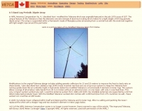 Modified version of the Telerana antenna which was orginially featured in the July 1979 issue of QST. The array is suspended within a framework made of fiberglass poles emanating from a central hub with the ends tied together with light weight rope around the perimeter. 10-15-20-30-40 meter band coverage
 -
 SM0DTK's 40-meter Moxon antenna project details the construction and deployment of a wire Moxon rectangle, specifically dimensioned for the 7 MHz band. The resource outlines the use of a _Moxon Rectangle Generator_ for calculating wire lengths and the fabrication of plexiglass supports for corners and the feeding point. It describes the practical challenges of elevating the antenna to approximately **14 meters** using an aluminum tube and fiberglass rod, emphasizing the adjustment process for achieving the correct rectangular shape. The article presents comparative results against a 60-meter long-wire and a full-size 40-meter ground plane antenna. The Moxon demonstrated significant directional gain towards the west, facilitating DX contacts in the Caribbean with **100 watts**, while simultaneously reducing QRM from strong eastern European stations. The SWR was reported as perfect without the need for an antenna tuner, validating the design's effectiveness for targeted signal enhancement and interference mitigation.
 -
 Selecting an appropriate antenna system for shortwave broadcasting involves evaluating various types based on performance, cost, and operational parameters. This resource details the critical specifications for broadcast antennas, including average and peak power ratings, directivity, takeoff angle (TOA), horizontal beamwidth, and gain, emphasizing that a 100-kW transmitter requires an antenna rated for 150 kW average and 400 kW peak. It clarifies that low TOA signals travel thousands of kilometers, while high TOA is for local coverage, and nearly all modern shortwave broadcast antennas are horizontally polarized. The article explores specific antenna types, such as Log-Periodic Antennas (LPAs), which offer wide frequency ranges (e.g., 2-30 MHz) and directional patterns with 11 dBi gain, costing from $20K to over $100K for multi-curtain versions. Dipole arrays, also known as curtain antennas, are prevalent in international broadcasting, featuring steerable beams (±15° and ±30°) and mode-switching capabilities to alter TOA, with high/low pairs costing over $1 million. Fan dipoles are noted for omnidirectional patterns, smaller size, and lower cost for low-power applications, while rhombics, though simple, require resistive termination and incur several dB of I2R losses. Balun considerations are crucial, as most communications baluns are not rated for the higher average and peak powers of AM broadcast transmitters. Modern shortwave antennas utilize durable materials like Alumoweld wire rope for radiators and support elements, avoiding copper, fiberglass, or materials prone to stretching or deterioration. Feeder systems for high-power stations often require tapered-line baluns to convert 50-ohm unbalanced power to 300-ohm balanced for connection to the antenna.
 -
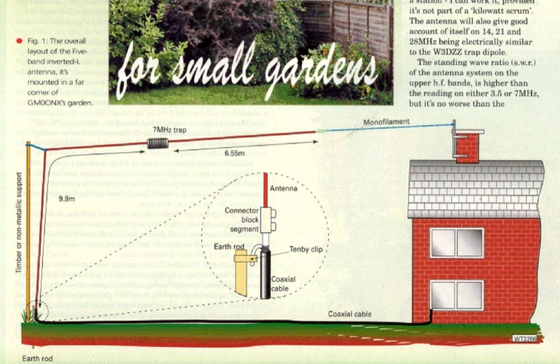 The Inverted L antenna is a versatile and efficient design suitable for small gardens, allowing amateur radio operators to operate on multiple bands. This project outlines the construction of a 5-band inverted L antenna, which can cover HF bands effectively. The design is particularly advantageous for those with limited space, as it requires minimal ground space while providing good performance. The antenna can be easily constructed using common materials, making it accessible for both beginners and experienced hams. In this guide, GM0ONX shares detailed instructions on how to build the inverted L antenna, including dimensions and tuning tips. The project emphasizes the importance of proper installation and grounding to ensure optimal performance. Additionally, it discusses the antenna's compatibility with various transceivers and the potential for portable operation. This resource is ideal for hams looking to enhance their station with a multiband antenna that performs well in limited space.
 -
 Examines the practical considerations and technical challenges of deploying mobile antennas for 10-meter operation, particularly for operators on the move. It addresses the inherently _lossy_ nature of shortened, loaded vertical antennas typically used in mobile configurations, encouraging hams to view these limitations as engineering challenges. The resource provides actionable advice on safeguarding vehicle electronics, selecting appropriate cabling like _RG-213_, and properly grounding antenna mounts to the vehicle chassis. Specific mounting strategies are detailed, including roof, trunk lip, and side-mounting for trucks and vans, along with their respective advantages and drawbacks. It emphasizes the importance of a robust ground plane and suggests methods for improving grounding beyond simple set screws. The article also touches on antenna choices, mentioning "bugcatchers" and "Hamstick types" as viable options for 10 meters. Furthermore, the guide transitions to stationary mobile operation, where antenna options expand significantly. It outlines how to deploy portable dipoles or 2-element beams from a parked vehicle, offering practical tips for assembly, storage, and mast guying using simple materials like a concrete block. It notes that a 5/8 wavelength height, approximately **20 feet** on 10 meters, often yields good short-skip and DX performance, even with a take-off angle above **20 degrees**.
 -
 The article details antenna tuning procedures, emphasizing SWR measurement and adjustment for both mobile and base station setups. It explains that SWR (Standing Wave Ratio) is the ratio of transmitted power to reflected power, with high SWR indicating poor impedance match and potential damage to a transceiver's final amplifier. Specific instructions are provided for CB antennas operating between 26-27 MHz, recommending initial SWR checks on channels 1, 20, and 40 to determine if the whip needs shortening or lengthening. Adjustments should be made in small increments, approximately 1/4 inch at a time, aiming for an SWR of 1.5:1 or better. For _Ham radio_ and other antennas, the same tuning principles apply, with a strong caution regarding RF energy exposure when operating at higher power levels. The resource suggests tuning base antennas at ground or roof level before final installation to simplify adjustments. It also advises rechecking SWR after final installation to confirm no changes occurred. The _Alpha Rubicon_ resource highlights the importance of a good ground plane for mobile antennas and proper coax routing to avoid pinching or proximity to electrical wires.
 -
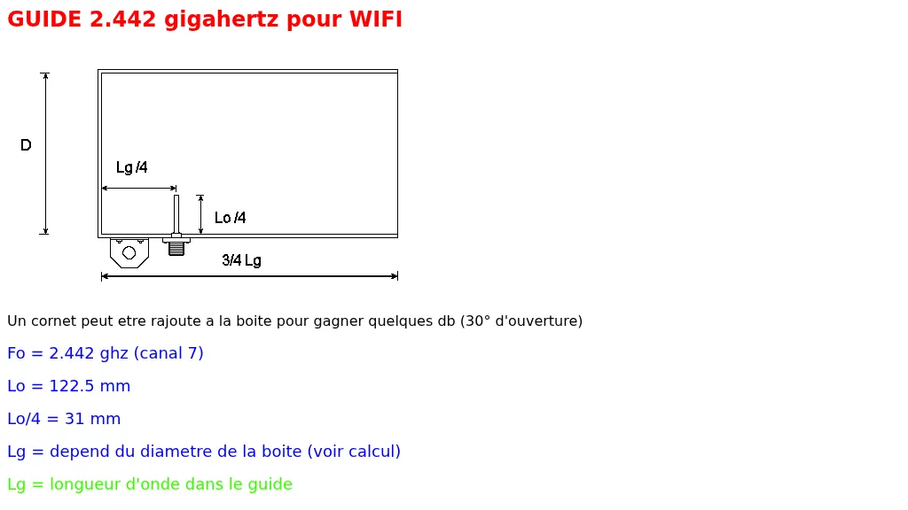 Demonstrates the construction of a 2.4 GHz horn antenna, specifically designed for WiFi applications, with the potential to add several dB of gain. The resource focuses on the critical dimensions and calculations required for proper operation, including _wavelength_ (Lo) and guide wavelength (Lg) based on the operating frequency (Fo) of 2.442 GHz, corresponding to channel 7. The guide provides a table of European WiFi frequencies, ranging from 2.412 GHz to 2.477 GHz, highlighting the specific channel 7 as the design target. It details how the length of the waveguide (Lg) depends on the diameter of the enclosure, offering a practical approach to antenna construction. This project outlines the necessary measurements like Lo/4 at **31 mm** and provides a link to an external calculator for further design specifics. The horn design aims for a 30-degree beamwidth, making it suitable for focused signal transmission or reception.
 -
 Automatic Link Establishment (ALE) is a digital signaling protocol enabling HF radio stations to automatically establish communication links, crucial for emergency and disaster relief operations. HFLINK serves as a central international resource for ALE High Frequency Communications, HF Selective Calling (SELCALL), and general HF interoperability. The platform provides extensive information on ALE operation, including frequency networks, band plans, and software like _PCALE_ for amateur radio integration. It also documents significant events such as the _HF Interoperability Exercise (HFIE)_ and the _Global Simulated Emergency Test (GlobalSET)_, which allow ham operators to gain real-world experience in interoperable HF communications, often using specific frequencies like the USA 5 MHz ALE simplex frequency 5371.5 kHz USB. The site features articles on antenna types popular among ALE users, such as autotuners and broadband antennas like the _T2FD_ and the Broadband Butterfly Terminated Dipole (BBTD).
 -
 The BV6 50 MHz Yagis resource details the construction of two distinct Yagi antenna designs for the 6-meter band, specifically a 1-wavelength (1wl) model and a 2.1-wavelength (2.1wl) model. The 1wl Yagi, with a boom length of 5.850m, achieves a gain of **9.4 dBd**, while the 2.1wl Yagi, spanning 12.90m, boasts a gain of **11.9 dBd**. These designs adhere to a proven methodology for optimizing current slope and maintaining constant phase delay across parasitic elements, ensuring high gain per boom length and an _excellent pattern_. Both designs target a 50-ohm input impedance, facilitating straightforward feeding with a robust folded dipole. Final verification using NEC-II software confirmed the antennas' exceptional stacking capabilities, yielding stacking gains exceeding **5.8 dB** for a 2x2 array with minimal mutual detuning. The resource provides common mechanical data, including boom and element diameters, and specifies element lengths corrected for boom diameter. While the original _DUBUS Technik V_ publication contained incorrect element lengths, this resource provides the accurate dimensions for proper construction, emphasizing the use of readily available materials for cost-effective amateur radio deployment.
 -
 Wire antennas requires a special coupling network to properly couple my 50 ohm coax to the antenna's high impedance (5000 ohms)
 -
 The "Largest YU Moxon" document meticulously details the design and construction of a substantial multiband Moxon antenna, primarily for 80m, 40m, and 20m operation. It presents specific design parameters derived from NEC-based simulations, including a 4-element 80m Moxon with 37 dB F/B and 7.81 dBi gain on a 47m boom, a 4-element 40m Moxon with a bidirectional pattern, and a 6-element 20m Moxon optimized for specific side lobes. The resource provides precise element lengths and spacing in meters for each band, alongside measured SWR results across the 3.650-3.800 MHz, 7.000-7.100 MHz, and 14.000-14.350 MHz segments. The construction narrative outlines the challenges and solutions encountered by the YU team, including the use of trees for support, the creation of "ugly" air-choke baluns from RG-58 cable wound on plastic bottles for each band, and the meticulous process of attaching wires to a rope boom. It documents the physical dimensions of the vineyard site (47 x 38m) and the azimuth orientation (340 degrees) chosen for the antenna. The document is distinctively useful for its practical insights into large-scale antenna deployment in a field environment, offering real-world SWR measurements and anecdotal performance reports from CQWW contest operations. It includes numerous photographs illustrating the construction process, the team members, and the finished antenna structure, providing visual context to the technical details.
 -
 Examines the operational principles of loading inductors within **mobile HF antennas**, clarifying their role in canceling capacitive reactance rather than physically replacing missing antenna length. It meticulously details how current distribution is influenced by stray capacitance and termination impedance, rather than the physical length of wire within the coil itself. The resource provides a deep dive into the behavior of inductors, emphasizing that a loading coil functions identically to any other inductor in an electronic circuit, with its characteristics determined by its design and surrounding impedances. This article specifically addresses common misconceptions, such as the idea that loading coil current is reduced by standing waves or that coils introduce a significant electrical-degree phase delay related to conductor length. It explains that magnetic flux coupling within the coil causes charges to move at light speed, resulting in minimal time delay across the inductor, especially in well-designed, compact units. The author, W8JI, presents both theoretical explanations and empirical measurements to support these points, including data from various antenna configurations. Furthermore, the content clarifies the distinction between voltage-current phase shift within an inductor and actual current time delay through it, using **SPICE models** and real-world observations. It highlights that large current taper in a loading coil often indicates poor antenna or tank circuit layout, rather than an inherent property of the inductor itself. The discussion also touches on the impact of stray capacitance on inductor Q and bandwidth, offering insights into optimal form factors for different applications.
 -
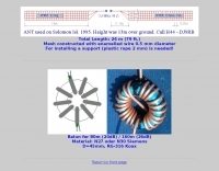 Mesh constructed with enamelled wire 0.5 mm diameter For installing a support (plastic rope 2 mm) is needed. Antenna used on Solomon Isl in 1995 H44/DJ9RB
 -
 Calculates precise dimensions for **Moxon rectangle** HF antennas, enabling hams to design antennas by inputting desired resonant frequency and wire diameter. This web-based tool, version 0.5, is a PHP front-end developed by W4/VP9KF, based on a public domain BASIC program originally authored by L. B. Cebik, W4RNL. It generates critical measurements for the driven element and reflector, ensuring proper spacing and element lengths for optimal performance. User feedback confirms the calculator's accuracy, with one user reporting resonance within 50 Hz of the design frequency for an 18 MHz antenna, eliminating the need for SWR adjustments. This contrasts with other online tools that resulted in significant frequency discrepancies. The tool's precision facilitates building **directional antennas** for specific bands, contributing to effective DXing and contesting operations.
 -
 JJ0DRC's HF multi-band delta loop antenna project, initially conceived during the waning peak of Cycle 23, addresses the common challenge of achieving effective DX operation from a small residential lot in Japan. Dissatisfied with a ground plane antenna's performance in SSB pile-ups, the author sought a beam-like solution without a tower, drawing inspiration from a JJ1VKL article in CQ Ham Radio Sep. 2000. The antenna, constructed in October 2000, employs two 7.2-meter fishing rods (37% carbon fiber, reinforced with cyano-acrylate glue and aluminum tape) and 1mm enameled wire, fed by an Icom AH-4 external antenna tuner. While the exact beam pattern remains unmeasured, JJ0DRC observed a significantly higher callback rate compared to dipole antennas, particularly on higher bands. The system's circumference length of 15-20m is crucial for maintaining a good beam pattern across HF bands, though performance on lower bands like 80m, 40m, and 30m becomes less directional as the length deviates from a full wavelength. Ongoing maintenance addressed degradation issues, including aluminum tape cracking and wire breakage at connection points due to strong winds (often exceeding 10-15m/s in winter). The author reinforced rod connections with IRECTOR PIPE SYSTEM components and INSU-ROCK ties, and improved wire attachment methods using Cremona rope and epoxy bond to enhance durability.
 -
 Illustrates the specific wiring and configuration steps required to interface an SGC-230 Smartuner with an Icom IC-706 HF/VHF/UHF transceiver. The document details the necessary connections for power, control, and RF signal paths between the two devices, ensuring proper impedance matching and automatic antenna tuning functionality. It specifies the pin assignments for the IC-706's ACC socket and the SGC-230's control port, crucial for successful integration. Outlines the operational considerations for the combined system, including initial setup procedures and potential troubleshooting tips for common connectivity issues. The resource presents a clear, diagrammatic representation of the interconnections, which aids in visual comprehension of the required cable fabrication or modification. Covers the specific settings within the IC-706 menu that need adjustment to enable external tuner control, such as the 'TUNER' function and other relevant parameters. This ensures the transceiver correctly communicates with the SGC-230 for efficient antenna tuning across various amateur bands.
 -
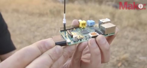 The project outlines the process for constructing a low-power FM broadcast transmitter using a Raspberry Pi Zero, a simple wire antenna, and battery power. It details the software installation steps for PiFM and MPG123, essential for generating and transmitting audio. The resource provides instructions for configuring the Raspberry Pi to broadcast FM signals, including command-line operations for initiating transmission and playing audio files. It specifically focuses on the Raspberry Pi Zero's capabilities for this application, highlighting its cost-effectiveness and minimal hardware requirements. The content presents a practical, hands-on approach to creating a basic FM transmitter, suitable for short-range, experimental broadcasting. It includes guidance on testing the FM output and ensuring proper operation of the software components. The project emphasizes the use of readily available components and open-source software to achieve functional RF output.
 -
 M0VEY shares insights into constructing a 160-meter mobile DX aerial, detailing the process of sourcing materials and assembly. The project began with a goal to avoid a £50 commercial antenna, instead utilizing a £10 reel of _enamelled copper wire_ and salvaged components like alloy tent poles and plastic water pipe. A friend fabricated a custom stainless steel tube for mounting, featuring a 3/8” thread for a mag-mount, enabling secure vehicle attachment. The aerial's design incorporates four alloy tubes, one plastic tube, and a five-foot whip, engineered to split into two pieces for convenient storage. The loading coil, wound with approximately 115 feet of 0.75mm wire onto a plastic former, was then sealed with blue heat shrink. M0VEY reports successful operation, making contacts across the UK and Europe, with the aerial standing about ten feet tall for local nets at 1.972 MHz and taller for the DX window around 1.845 MHz. Future plans include a base-loaded 160m aerial and an 80m version, leveraging components from the existing _160m DX Mobile Aerial_ to maintain a similar overall size with a smaller coil.
 -
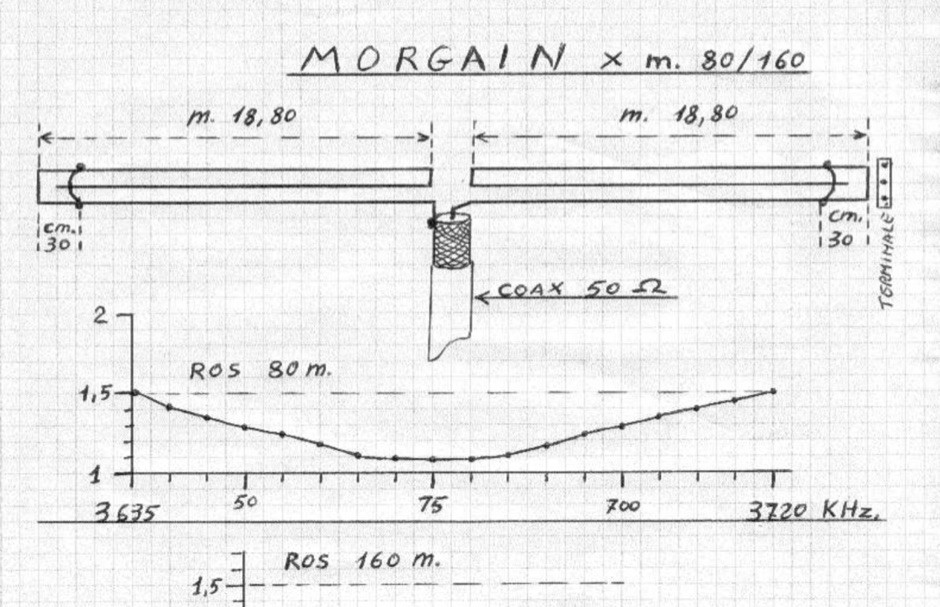 A 37.6-meter Morgain antenna design provides dual-band operation on 80 and 160 meters without traps. The antenna uses 1.5 mm² stranded copper wire with vinyl insulation, commonly found as domestic electrical wire. Tuning involves adjusting lateral jumper wires for the 80-meter band, with initial positions 30 cm from the arm ends, yielding 3635–3715 kHz resonance with SWR below 1.5:1. For 160 meters, a straight wire length of 18.80 meters per arm is critical, achieving 1840–1850 kHz resonance with SWR below 1.1:1. The Morgain antenna exhibits a 50-ohm feed-point impedance, allowing direct connection of 50-ohm coaxial cable like RG-8X, which handles approximately 500 watts. Spacers and the central plate are constructed from 1 mm thick green fiberglass laminate, with spacers measuring 11 cm and installed every 1.90 meters. The central plate is 11 × 11 cm, designed to secure the coaxial cable mechanically. End supports utilize 3–6 mm thick bakelite terminal spacers, tensioned with nylon ropes.
 -
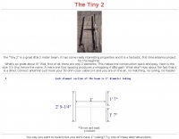 The "Tiny 2" is a great little 2 meter beam. It has some really interesting properties and it is a fantastic first time antenna project for the beginner.
 -
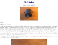 The QRP choke balun described utilizes a high permeability ferrite rod and RG-174 coax, aiming to present high impedance to common-mode currents across the HF spectrum. The construction involves winding as many turns of RG-174 as possible around the ferrite rod, then encapsulating the assembly with hot glue. This design prioritizes maximizing inductance to suppress unwanted shield currents, particularly in unbalanced antenna configurations. While the balun's effectiveness is subjectively reported as good, a potential design consideration involves the dielectric properties of the hot glue. This material could increase turn-to-turn capacitance, potentially reducing the balun's performance at higher HF frequencies, though this specific aspect has not been formally tested by the author, _AA5TB_. The project serves as an illustrative example of a practical, junk-box construction rather than a rigorously engineered solution. Photographs detail the evolution of the balun, from the initial winding process to its integration within a _B&W dipole center insulator_ and final camouflaged assembly.
 -
 Over **10 million** antennas and flags have been sold worldwide by Firestik Antenna Company, a veteran-owned manufacturer specializing in both CB and amateur radio communication products. Their offerings include a range of antennas, mounting accessories, and coaxial cables, designed for various mobile and fixed applications. The company provides technical support and maintains a network of dealers for product availability. Firestik products are known for their fiberglass construction, which is evident in their _Firestik_ and _Firefly_ antenna lines. The company also produces unique items like the "342 mile per hour Firestik flag," highlighting their diverse manufacturing capabilities beyond just radio antennas. They emphasize their commitment to quality and customer service, including direct technical assistance. The company is located in Tempe, Arizona, and operates under the registered trademark of _Pal International Corporation_. They actively protect their brand, including variations like Firestick and Firestix, ensuring proper representation of their products in the market.
 -
 Operating a ZS6BKW antenna often involves understanding its lineage from the _G5RV_ design, with specific modifications by ZS6BKW to optimize performance on several bands. Through computational analysis and field measurements, the antenna's dimensions were refined to allow operation on 10, 12, 17, 20, and 40 meters without an antenna tuner. For 80, 30, and 15 meters, a tuner is necessary, though efficiency on 30 and 15 meters is noted as not particularly high. The physical configuration consists of two 13.755-meter radiating elements fed by a 12.20-meter section of 450-ohm ladder line. Tuning the antenna on the 20-meter band is critical, and any deviation in the ladder line's characteristic impedance necessitates recalculating the element lengths. The design is also referenced in the 12th edition of _Rothammel's Antennenbuch_, page 219. Proper common mode current suppression is crucial at the transition from ladder line to coaxial cable. This can be achieved with a common mode choke, such as several turns of coax wound into a coil or over a ferrite toroid like an Amidon T130. While a 1:1 balun is an option, it may introduce issues.
 -
 A _Topfkreis_ antenna, also known as a "bicycle pump" antenna, is presented as a simple vertical design for the 70 cm band. This variant of the J-pole antenna is notable for not requiring a ground plane, simplifying deployment. The construction details specify using aluminum tubing for the radiating element, with precise measurements for the quarter-wavelength outer tube (32 mm diameter) and the three-quarter wavelength inner sliding tubes (10 mm and 8 mm). Feeding is via a 50-ohm coaxial cable connected 90 mm from the base of the central tube. This design can achieve a gain of **4 to 6 dB** when properly tuned using the adjustable radiating element. The article details the fabrication of a critical aluminum washer, suggesting a method using a hole saw and a drill press as a lathe for precise adjustment. The illustrated example is specifically for the 70-centimeter band, and the author, Pop, clarifies construction points in the comments, including material choices and assembly techniques, ensuring a robust build for VHF/UHF operation.
 -
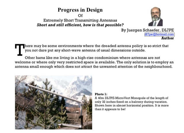 Progress in Design of Extremely Short Transmitting Antennas Short and still efficient, how is that possible? By Juergen Schaefer, DL7PE author of the MicroVert antenna concept. The MicroVert introduced in this document is an extremely short and hardly visible short-wave antenna with outstanding radiation properties
 -
 Helical antennas have long been popular in applications from VHF to microwaves requiring circular polarization, since they have the unique property of naturally providing circularly polarized radiation. Paul Wade W1GHZ
 -
 Presents a construction project for a linear-loaded 40-meter rotatable dipole, detailing the design evolution from mid-element coils to 300-ohm twinlead loading. It covers material selection, including repurposed fishing poles and EMT conduit, and outlines the assembly process for the antenna elements and mounting plate. The resource provides specific measurements for element lengths and linear loading sections, along with SWR plots demonstrating the antenna's resonance at 7.035 MHz with a 1.1:1 SWR, and bandwidth up to 7.120 MHz below 2:1 SWR. The article documents the antenna's performance during various RTTY and CW contests, including the SARTG RTTY and SCC RTTY contests in August 2006, and the ARRL DX CW and CQWW WPX RTTY contests in February 2007. It reports successful operation at 500-1000W, noting improved performance after replacing a faulty coax cable. Specific DX contacts from British Columbia, including stations in Europe and South Africa, are listed, illustrating the antenna's capability despite its shortened length and relatively low height of 55 feet. The content highlights practical considerations such as weatherproofing the connections and supporting the fiberglass elements to prevent sagging. It also includes a brief comparison to an inverted-V at similar height and a ground-mounted vertical, noting the rotatable dipole's quieter reception. The author shares insights into the iterative design process and tuning adjustments made to achieve optimal resonance.
 -
 The Coaxman by Clear Signal Products, Inc. features a complete Wireman line of coaxial cable and antenna wire. Antenna wire, baluns, coax connectors, insulators, ladder line, magnet wire, rope.