Search results
Query: antenna cal.
Links: 1264 | Categories: 63
Categories
- Antennas > 20M > 20 meter Vertical Antennas
- Antennas > 40M > 40 meter Vertical Antennas
- Antennas > Antenna Calculators
- Radio Equipment > HF Vertical Antenna
- Manufacturers > Antennas > VHF UHF Microwave > Vertical Antennas
- Manufacturers > Antennas > HF > Vertical Antennas
- Antennas > 6M > 6 meter J-Pole Antenna
- Antennas > 6M > 6 meter Yagi Antennas
- Software > Antenna analysis
- Antennas > Theory > Antenna Gain
- Shopping and Services > Antennas
- Antennas > Vertical
- Technical Reference
- Antennas > 160M
- Antennas > 17M
- Antennas > 20M
- Antennas > 30M
- Antennas > 40M
- Antennas > 70cm
- Operating Modes > Satellites > AO-51
- Technical Reference > Arduino
- Radio Equipment > Antenna Analyzers > Array Solutions AIM 4170D
- Antennas > Bazooka
- Operating Aids > Beginner's Guides
- Shortwave Radio > Beginner's guides
- Ham Radio > Regional > Brazil
- Radio Equipment > HF Vertical Antenna > Butternut HF2V
- Antennas > C-Pole
- Shopping and Services > CB Radio Stores
- Radio Equipment > HF Vertical Antenna > Cushcraft R5
-
 Selecting appropriate cabling for amateur radio installations, whether for antenna feedlines, control lines, or station wiring, is critical for optimal performance and safety. This resource provides access to a manufacturer specializing in a broad range of electronic and electrical cables, including options suitable for various ham radio applications. Their product line encompasses standard and custom cable solutions, designed to meet specific operational requirements for both indoor shack setups and outdoor antenna systems. The company emphasizes _proven quality_ and compliance, with products certified by the Canadian Standards Association (CSA), Underwriters Laboratories (UL), and Intertek (ETL). Their quality management system is registered to _ISO 9001:2015_, ensuring consistent product standards. They offer competitive pricing and utilize AI-logistic tools for reliable on-time delivery, serving customers globally with technical support. Access to detailed technical specifications and an online quote tool is available for registered site members, facilitating precise cable selection for projects requiring specific impedance, shielding, or environmental ratings.
 -
 A remotely tuned 80m to 10m wire vertical antenna
 -
 Industrial Communication Engineers (ICE) was a manufacturer specializing in **RF components** and solutions for amateur radio and commercial applications. Their product line included a range of RF parts, various types of filters, and RF switching products designed to enhance station performance and mitigate interference. These components were critical for hams engaged in contesting, DXing, or general operating, providing means to improve signal integrity and manage complex antenna systems. The company's offerings addressed common operational challenges such as RFI and TVI, with products like **low pass filters** and antenna filters. While the specific technical specifications of their product range are no longer available, such components typically provided significant attenuation of unwanted harmonics and out-of-band emissions, crucial for maintaining a clean signal and preventing interference with other electronic devices. The current status indicates the domain is for sale, suggesting the manufacturing operations have ceased.
 -
 The NCDXF/IARU International Beacon Project operates a worldwide network of 18 high-frequency radio beacons, continuously transmitting on 14.100, 18.110, 21.150, 24.930, and 28.200 MHz. These beacons, initially launched in 1979 with a single station and expanded to the current 18-beacon system in 1995, provide reliable signals for both amateur and commercial users to assess current **ionospheric propagation** conditions. The system's design, construction, and operation are managed by volunteers, covering hardware and shipping costs. The resource details the evolution of the beacon network, including the transition from Kenwood TS-50s transmitters to Icom IC-7200 radios with a new controller design implemented in 2015. It explains how listening for these 100-watt signals, transmitted to vertical antennas, allows operators to determine band openings and optimal propagation paths globally. The content also references three QST articles providing historical context and technical specifics of the beacon project. Practical information includes methods for identifying transmitting beacons via a schedule or specialized software like FAROS and Skimmer, which integrates with the **Reverse Beacon Network** for automated monitoring.
 -
-
 This online microstrip patch antenna calculator determines the length and width of a microstrip patch antenna for a given frequency
 -
 A Unique VHF Antenna with gain over a J-Pole Jose I. Calderon, DU1ANV
 -
 The _National Contest Journal_ (NCJ) serves as a dedicated resource for amateur radio contesters, providing in-depth articles, operational strategies, and technical insights. Published bimonthly by the ARRL, it covers a wide array of contesting topics, including antenna systems, station optimization, operating techniques, and rule interpretations for major events like the NA Sprint and various QSO Parties. The journal aims to enhance the competitive edge of participants across all skill levels, from casual operators to serious multi-operator teams, by sharing experiences and data from high-scoring stations. NCJ content frequently includes detailed analyses of contest results, offering breakdowns of scores, participant statistics, and comparisons of operating strategies. Readers can find practical advice on improving their contest performance, such as optimizing logging software usage or maximizing **run rates**. The journal also features columns on specific contest modes like RTTY and provides updates on rule changes and upcoming events, helping contesters prepare for future competitions and achieve better results, often leading to **top 10** finishes in their respective categories.
 -
 An off centre fed dipole, with 10 feet of vertical radiator. It needs no tuner on 40m, 20m and 10m by M0UKD
 -
 TurboLog is a station management and logging program designed for amateur radio operators, providing robust database and logging functionalities. It features fully integrated support for controlling typical radio station equipment, including transceivers, packet radio TNCs, Morse and voice keyers, and digital mode terminals. The software also incorporates antenna switching capabilities and acoustic alerting, streamlining station operations for DXing and contesting. The program's utility extends to award tracking for entities like DXCC and IOTA, alongside comprehensive callbook and ham database integration. It supports log import and export, QSL label generation, and includes TNC drivers for packet radio. The trial version allows users to evaluate its extensive features before commitment, making it a versatile tool for managing complex amateur radio station configurations and operational data.
 -
 About longwire antennas, technically to be a true longwire an antenna needs to be at least one wavelength long, but common use of the term by Hams is for any random wire length that is end fed.
 -
 Demonstrates the construction of a 144 MHz turnstile antenna, detailing its design for omnidirectional, horizontally polarized VHF operation. The resource outlines the physical dimensions and materials required, including specific lengths for the radiating elements and the use of _RG-58_ coaxial cable for phasing. It covers the assembly process, emphasizing the critical spacing and connection points to achieve the desired radiation pattern and impedance matching for the _2-meter band_. The article presents measured _SWR_ performance across the 144-146 MHz segment, showing a low SWR of 1.2:1 at 144.5 MHz, which is suitable for general VHF use. It compares the turnstile's performance to a 9-element Yagi, noting the turnstile's advantage in providing consistent signal strength from all directions without requiring a rotator. Practical application for local FM simplex and repeater operations is implied, offering a simple yet effective antenna solution for fixed or portable stations.
 -
 Deploying robust antenna infrastructure for both fixed and portable operations often requires specialized support structures capable of withstanding environmental stresses while providing optimal radiating element placement. SMC offers a range of solutions, including pneumatic masts and push-up masts, designed to facilitate rapid deployment and reliable long-term support for various antenna types. Their product line encompasses antenna mounts, poles, and complete antenna systems, addressing the critical need for stable and efficient RF communication. The company's offerings extend to HF antennas, including dipoles and _NVIS_ (Near Vertical Incidence Skywave) antennas, which are crucial for short-range regional communications on bands like 80m and 40m. These systems are engineered for durability and performance, ensuring signal integrity across diverse operating conditions. With over **65 years** of experience, SMC has established itself as a global manufacturer in this niche. Their product portfolio also includes antenna support towers, catering to more permanent installations requiring significant height and load capacity for multiple arrays.
 -
 Build an effective dipole antenna that needs much less space by adding two loading coils. This online calculator tells you how.
 -
 eham users review of the Cushcraft r5 vertical antenna
 -
 One point eight MHz to 30 MHz is the operational bandwidth for this 4:1 Ruthroff voltage balun, designed to interface an unbalanced T-Match network with a balanced antenna system. The project details the construction using a _T200-2_ powdered iron toroid core, tightly wrapped in PVC electrical tape for insulation, and wound with 17 double bifilar turns of 1.25mm enamelled copper wire. This outboard balun offers flexibility, allowing hams to trial various baluns based on antenna system and impedance characteristics, rather than integrating it directly into the tuner. The resource includes a schematic of the balun, a wiring diagram showing winding connections, and a table suggesting alternative toroid cores like the T80-2 or T400-2 with corresponding winding counts. Component sourcing is straightforward, listing items such as the _Amidon_ T-200-2 core, SO-239 connector, and a sealed polycarbonate enclosure from Jaycar. Performance evaluation was conducted using an _AIM 4170C_ antenna analyser, demonstrating efficient 1:4 voltage transformation across the specified HF spectrum. Further efficiency tests involved measuring RF power loss at various frequencies, revealing minimal loss—less than 0.7 dB from 3.6 MHz to 30 MHz, and only 2.0 dB at 1.8 MHz. These measurements, performed under ideal 50-ohm conditions, confirm the balun's effectiveness as a low-loss interface for multi-band antenna systems. The page also links to several other balun and unun projects, including 1:1 current and voltage baluns, and 9:1 voltage ununs, providing a broader context for impedance matching solutions.
 -
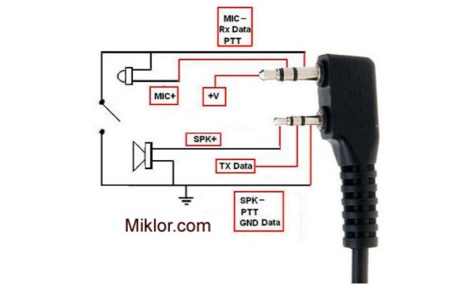 Speaker Microphone Pin Out, Dual PTT Switching,Programming Cables, SMA Antenna Connection, Extended Antenna Threads for Baofeng UV 3, UV 5 Series handheld transceivers
 -
 A simple and awesome wire monoband antenna, very usefull for portable and dxpeditions usage, consist of two elements, a driver and the reflector. This endfed halfwave gives a very low take off angle and is very suited for chasing DX.
 -

-
 The resource presents a detailed schematic for constructing a dual-band vertical antenna, specifically designed for operation on the 2-meter and 70-centimeter amateur radio bands. It illustrates the physical layout, critical dimensions, and component placement necessary for successful replication. Key elements such as the radiating elements, phasing sections, and feed point are clearly depicted, providing a visual guide for radio amateurs undertaking a homebrew antenna project. The diagram specifies the lengths for the VHF and UHF sections, indicating how these elements are integrated to achieve dual-band functionality from a single coaxial feedline. It also implies the use of common materials readily available to most experimenters, focusing on simplicity and effectiveness in its design. The visual format of a GIF image ensures direct access to the construction details without requiring extensive textual interpretation. This schematic serves as a practical reference for hams interested in building a compact, efficient vertical antenna for local and regional FM communications, offering a proven design for immediate implementation.
 -
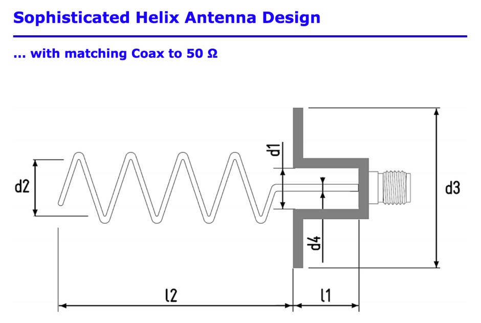 Helix antenna online calculator with match calculator
 -
 Presents a curated collection of newsletters dedicated to _Earth-Moon-Earth_ (EME) communications, primarily focusing on the 432 MHz band and higher microwave frequencies. The resource details various EME DX experiences and news contributions from operators like K2UYH (W6/PA0ZN), offering insights into successful moonbounce contacts and operational strategies. It serves as an archive of specialized content for those engaged in or interested in extreme weak-signal propagation via the moon. The newsletters provide practical information on achieving EME contacts, often including details on station setups, antenna arrays, and signal reports from challenging DX. For instance, operators might report achieving contacts over **750,000 km** round trip, demonstrating the feasibility of long-distance communication on UHF and microwave bands. The content differentiates itself by concentrating on the unique technical and operational aspects of EME, which contrasts significantly with terrestrial DXing, providing a specialized knowledge base for advanced amateur radio operators.
 -
 Optimizing the ZS6BKW antenna for full HF band coverage often requires specific modifications beyond its standard configuration. This resource details several enhancements, beginning with a simple series capacitor to improve 80m SWR, a technique W5DXP found effective for permanent installation due to its minimal impact on higher bands. Further improvements include a 10-inch parallel open stub for 10m resonance, shifting the frequency to 28.4 MHz with an SWR of approximately 1.8:1, a practical solution for Technician class operators. The document then explores a switchable matching section, adding or subtracting one foot of ladder line at the 1:1 choke-balun, which significantly impacts higher frequency bands and eliminates the need for a tuner on 17m. W5DXP's _AIM-4170D_ antenna analyzer measurements confirm these effects. More advanced modifications involve a parallel capacitor for further 80m SWR reduction, requiring remote switching for multi-band operation, and relay-switched parallel capacitors at specific points on the 450-ohm matching section to achieve low SWR on 60m, 30m, and 15m. These detailed steps, including _Smith chart_ analyses for the challenging bands, aim to transform the ZS6BKW into a truly all-HF-band antenna, reflecting W5DXP's practical experience in antenna tuning.
 -
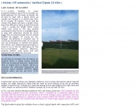
 This 80M antenna is a pair of raised 1/4-wave verticals
 -
 An online J-Pole antenna calculator that need just to input the frequency and calculates in inch size of each element
 -
 The page provides a project for an helical dipole for the 40 meters band, resonating on 7 MHz, created by PY1ZFK based on a design by DL8VO. It includes detailed instructions on building the antenna.
 -
 SecondHandRadio.com provides a platform for the amateur radio community to buy, sell, and swap used, surplus, and obsolete electronics and electrical equipment. The site facilitates transactions for a wide range of items, including ham radio transceivers, test equipment, shortwave receivers, antennas, and vintage radio components like tubes. Users can place classified advertisements with photos at no cost, catering to individuals, radio clubs, and commercial dealers seeking to liquidate or acquire gear. The platform emphasizes ease of use with a straightforward sign-up process and no associated fees or commissions for listing or selling items. It positions itself as a primary resource for used electronics within the USA, fostering a direct connection between sellers and buyers without intermediary charges. The service supports various categories beyond amateur radio, extending to military radios and antique equipment, thus serving a broad spectrum of radio enthusiasts and collectors.
 -
 Presents a QRP AM/CW transmitter project specifically designed for the 10-meter band, utilizing a crystal oscillator and a collector-modulated AM oscillator. The design employs a 2N2219(A) transistor in a Colpitts configuration, generating 100 to 350 mW of RF output power depending on the 9-18 Volt supply voltage and modulation depth. Frequency stability is maintained by a 28 MHz crystal, with fine-tuning possible via a Ct1 trimmer capacitor for approximately 1 kHz adjustment. The resource details the RF oscillator stage, implemented with a 2N2219 NPN transistor, emphasizing frequency stability and low power dissipation. It also covers the amplitude modulation stage, managed by a 2N2905 PNP transistor, which impresses audio information onto the carrier. Selective components (C3, C4, C7, C5) enhance voice frequencies within a +/- 5 kHz bandwidth, and modulation depth is controlled by R2 and R3. The project includes a 3-element L-type narrow bandpass filter (Ct3, L3, C10) to suppress harmonics and ensure a clean output signal. The project provides a complete schematic diagram, a comprehensive parts list including specific capacitor, resistor, and inductor values, and construction notes for the coils (L1, L2, L3). It also offers practical advice on enclosure requirements, suggesting an all-metal case or a PVC box with graphite paint for RF shielding. Operational parameters such as current draw (27mA@9V to 45mA@16V) and input impedance (50 Ohms) are specified, alongside guidance on antenna matching and the importance of a valid amateur radio license for 10-meter band operation.
 -
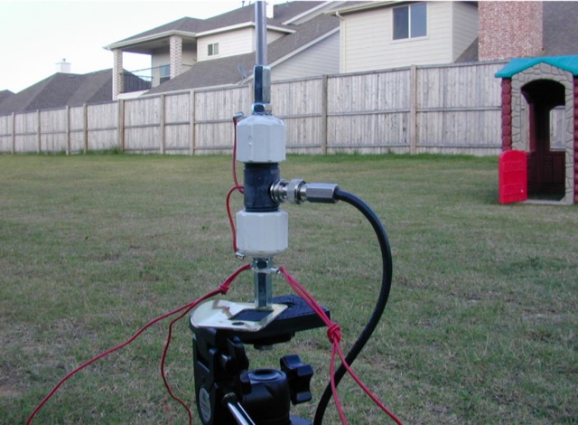 A multi-band portable vertical antenna can be built with relatively ordinary components obtained from the local hardware store, including replaceable loading coils
 -
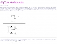 Configurations of the vertical antenna arrays used at 6Y2A
 -
 The ZS6BKW multiband antenna, an optimized variant of the classic G5RV, features a 102-foot (31.1 m) horizontal span and a 39.1-foot ladder line matching section. This design, derived by G0GSF (formerly ZS6BKW) in the early 1980s using computer programs and _Smith charts_, aims for improved SWR across multiple HF bands compared to its predecessor. Construction details specify Wireman 554 ladder line and #14 AWG THHN copper wire for the radiators, with precise instructions for determining the velocity factor (VF) of the ladder line using an antenna analyzer or dip meter, ensuring accurate physical length for the matching section. The radiator length is electrically 1.35 wavelengths for the 20-meter band, requiring careful trimming during tuning. Field measurements with an _AIM-4170C_ analyzer by KI4PMI and NC4FB demonstrated good SWR curves and bandwidth on 6, 10, 12, 17, 20, and 40 meters. The antenna was deemed unusable on 15 and 30 meters due to very high SWR, but an LDG AT-100PRO autotuner successfully brought 6 and 80 meters into tune. Contacts were made on 80, 40, 20, and 17 meters, including a **17-meter** contact to Spain. EZNEC models for 80-6 meters are provided, along with an AutoEZ model by AC6LA, which predicted good SWR for 80-10 meters. W5DXP's modifications for an all-band HF ZS6BKW are also referenced.
 -
 The _Italian VHF Beacons_ resource provides a detailed listing of active and QRT amateur radio beacons operating across VHF, UHF, and SHF bands within Italy. Each entry specifies the beacon's callsign (e.g., IQ1SP/B), operating frequency (e.g., 144.411 MHz), QTH locator (e.g., JN44VC), effective radiated power (ERP) in watts, and antenna configuration (e.g., Big Wheel, 4x Dipole, Yagi). This data is crucial for radio amateurs involved in propagation studies, equipment testing, and long-distance (DX) communication on these higher frequency bands, offering fixed signal sources for monitoring. This compilation, last updated in October 2005, serves as a historical snapshot of Italian beacon activity. For instance, it lists several 144 MHz beacons with ERPs ranging from **0.1W** to **10W**, and higher frequency beacons such as I8EMG/B on 1296.880 MHz and I3EME/B on 24192.132 MHz. The inclusion of QRT (Quiet Radio Teletype) status for many entries indicates the dynamic nature of beacon operations over time. Users can utilize this information to identify potential signal sources for band openings or to calibrate their receiving equipment against known transmissions.
 -
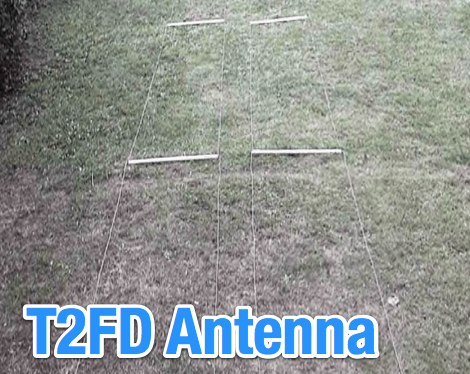 T2FD A practical construction article, which first appeared in the Electronic DX Press, contains a number of useful photos and detailed instruction to build this antenna by VK3BVW
 -

-
 A web site dedicated to hex beam homebrewing. The hexagonal beam has become a wildly popular antenna. It is a directional antenna that provides great performance and does not require a full scale, expensive tower.
 -
 Operating on the 2200m band (135.7-137.8 kHz) often presents challenges for amateur radio transceivers, which typically exhibit poor receiver performance at these very low frequencies. This project addresses the issue by providing a design for a dedicated 137 kHz antenna preamplifier, specifically tailored to improve signal reception for radios such as the _Yaesu FT-817_. The preamplifier circuit utilizes a low-noise FET input stage, crucial for minimizing self-generated noise and maximizing the signal-to-noise ratio from weak LF signals. The design includes a detailed schematic, component values, and construction notes, enabling homebrewers to build a functional unit. The goal is to achieve significant gain, making the faint signals on 2200m more discernible and improving overall band usability. Key design considerations include impedance matching to typical antenna systems and ensuring stable operation across the narrow LF segment. The circuit aims for a **low noise figure** and sufficient amplification to overcome the inherent limitations of general-purpose HF transceivers when operating below **200 kHz**.
 -
 Florida DXers meet every other month in Ft. Lauderdale to discuss DX, antennas and such. We host the DX forum at the Tropical Hamboree in Miami the first Saturday in Feb.
 -
 Operating an 80/40/20M fan dipole for DX is analyzed through EZNEC modeling, focusing on the antenna's performance in a real-world, low-height installation. The resource details the physical construction and SWR measurements of the fan dipole, comparing them against EZNEC simulations. It also incorporates High Frequency Terrain Analysis (HFTA) data to illustrate typical DX elevation angles for various regions from New England, providing a crucial context for evaluating antenna patterns. The analysis presents EZNEC-generated azimuth and elevation patterns for each band (80M, 40M, 20M) at specific frequencies, showing gain figures at different elevation angles relevant to DX propagation. It compares the modeled SWR with measured SWR, attributing discrepancies to coax attenuation. The study concludes with observations on the antenna's azimuth performance (omnidirectional within ±1.5 dB) and its less optimal elevation gain at desired DX angles, highlighting the impact of low antenna height on DX capabilities.
 -
 A very efficient 80 meter Counterpoise antenna designed to reduce ground losses from inadequate radial systems beneath inverted L antennas, a project by DM2GM and DM4IM based on the original K2AV antenna concept.
 -
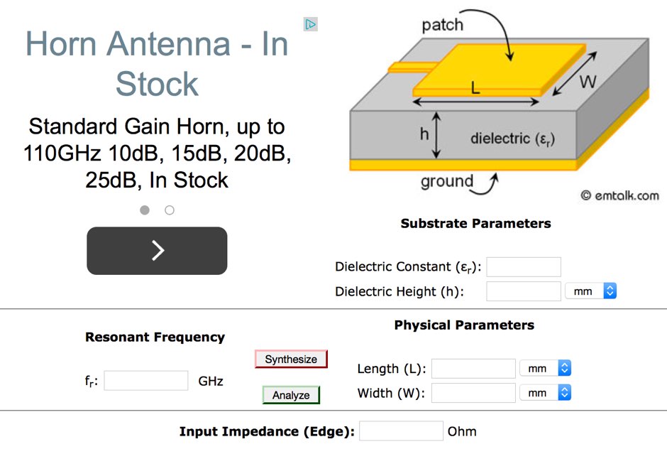
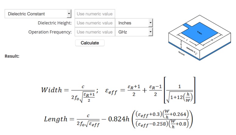 Microstrip Patch Antenna Calculator determines the length and width in millimeters of a rectangular patch antenna.
 -
 Practical applications for end-fed antenna transformers and safe, effective grounding
 -
 Demonstrates the construction and implementation of a **two-element phased vertical array** for 40 meters, utilizing _Christman phasing_ techniques. The author, W4NFR, details the process from building individual 1/4-wave aluminum verticals to integrating them into a phased system. The resource covers antenna spacing of 32 feet, elevated radial design, and the critical steps for tuning each vertical to achieve a 1.1:1 SWR before combining them. It also provides insights into calculating precise coax lengths for feedlines and the phasing delay line, emphasizing the use of an MFJ-269 Antenna Analyzer for verification. The finished system exhibits good front-to-back nulls, with an overall SWR ranging from 1.6:1 to 2.2:1, which is managed by an antenna tuner. The project includes detailed photos of the relay box, showing 12 VDC relays capable of handling 5KV, and the control box in the shack for switching between three different antenna pattern configurations. Static bleed-off chokes are incorporated for protection, and the construction emphasizes robust weatherproofing for outdoor elements.
 -
 This project details the construction of a **full-sized 40-meter vertical antenna**, born from a renewed interest in 7 MHz operation and a desire for improved effectiveness over simple dipoles. The author, K5DKZ, initially focused on VHF experimentation, which provided an inventory of aluminum tubing and fiberglass spreaders for this endeavor. Before this vertical, K5DKZ utilized an 80/40 meter inverted-vee trap dipole and a 40-meter broadband dipole, but now primarily uses a pair of full-sized, phased, quarter-wave verticals spaced 35 feet apart for serious 40-meter work. The construction involves a base-heavy design for stability, using a 44.5-inch section of 1-1/4 inch steel TV mast driven into 1-3/8 inch aluminum tubing, insulated by a 105-inch section of Schedule 40 PVC pipe. The assembly reaches 31 feet, close to the 32 feet required for a quarter-wavelength on 40 meters, with fine-tuning achieved by winding wire onto a fiberglass spreader. The design is explicitly presented as a foundation for a two-element 40-meter Yagi beam, outlining modifications like substituting aluminum for steel in the base and using an inductive hairpin match for the driven element. The article also discusses tuning considerations for a large 40-meter beam, noting the 100 to 200 kHz upward frequency shift when raised, and suggesting methods for installation on a tower. The author emphasizes the cost-effectiveness and good performance of the monopole approach, especially when multiple verticals are needed.
 -
 Calculating HF helical whip antenna for mobile or portable operation
 -
 Sherwood Engineering Inc. (SEI) offers a repository of technical presentations and white papers focused on optimizing amateur radio transceiver and receiver performance. Content includes detailed analyses of _roofing filters_, transmitted IMD, and receiver characteristics, with specific discussions on products like the Drake R-4C and Icom IC-781. Presentations from events such as Dayton Contest University (2008-2014) cover topics like "How To Optimize Rig Performance," "Transceiver Performance: 10 Years of Change," and "Choosing a Transceiver: Far from Simple." Additional white papers address HF mobile antenna efficiency, ground screen alternatives to buried radial systems, and common receiver problems with solutions. The site also provides historical product information for items like the SE-3 MK IV synchronous AM detector and various 455 kHz mechanical and crystal filters, though many products are no longer in production. Receiver test data and alignment tips for the R-4C are also available, offering insights into rig modifications and performance enhancements.
 -
 The grounded half loop describe in this article is basically a half wave length wire on 80 Meters. The 80M grounded half loop antenna, inspired by a 1984 QST article by SM0AQW, is a compact solution for limited spaces. Comprising a 127-foot wire fed against ground and supported by radials, it balances performance and practicality. Despite compromises in length and proximity to structures, the antenna delivers strong signal reports and effective multi-band tuning using an SGC 237 antenna coupler. Ideal for CW operation, it offers low SWR on 80-10M, though noise levels and safety considerations warrant attention. This versatile design excels in constrained environments.
 -
 A fractional bandwidth of up to 30:1 characterizes spiral antennas, making them highly effective across a very wide frequency range, often from 1 GHz to 30 GHz. The resource details two primary types: the **Log-Periodic Spiral Antenna** and the **Archimedean Spiral Antenna**, defining each with specific polar functions and illustrating their planar configurations. It explains that spiral antennas are typically circularly polarized, with a Half-Power Beamwidth (HPBW) of approximately 70-90 degrees, and a peak radiation direction perpendicular to the spiral plane. The content elaborates on critical design parameters affecting radiation, including the total length (outer radius) for lowest frequency, the flare rate ('a' constant) for optimal radiation versus capacitive behavior, the feed structure (often an infinite balun) for high-frequency operation, and the number of turns (typically 1.5 to 3 turns). It also discusses the theoretical impedance of 188 Ohms for Log-Periodic spirals, derived from Babinet's Principle, noting actual impedances are often 100-150 Ohms. The article presents a simple construction method for an Archimedean spiral, demonstrating VSWR and efficiency measurements. Measurements from a constructed spiral antenna show a VSWR that is fairly constant across the band, albeit with a mismatch loss of about 3 dB. The antenna efficiency remains around -5 dB (31.6%) across its operating range, indicating a decent wideband radiator despite opportunities for optimization.
 -
 The Gizmotchy high performance horizontal and vertical beam antenna for 2/6/10/11 meter bands
 -
 This page allows you to calculate in the most accurate way high-Q inductor coils.
 -
 The Remote Control Antenna Switch consists of two circuit boards. The control unit and the remotely controlled switch