Search results
Query: 8 band antenna
Links: 1419 | Categories: 68
Categories
- Antennas > 20M > 20 meter Dipole Antennas
- Antennas > 20M > 20 meter Vertical Antennas
- Antennas > 20M > 20 meter Yagi antennas
- Antennas > 40M > 40 meter Dipole Antennas
- Antennas > 40M > 40 meter Loop Antennas
- Antennas > 40M > 40 meter Yagi Antennas
- Antennas > 6M > 6 meter J-Pole Antenna
- Antennas > 6M > 6 meter Moxon Antennas
- Manufacturers > Antennas > VHF UHF Microwave > Discone Antennas
- Radio Equipment > HF Vertical Antenna
- Manufacturers > Antennas > VHF UHF Microwave > HT Antennas
- Manufacturers > Antennas > VHF UHF Microwave > Mobile Antennas
- Manufacturers > Antennas > VHF UHF Microwave > Quad Antennas
- Manufacturers > Antennas > HF > Quad Antennas
- Manufacturers > Antennas > VHF UHF Microwave > Satellite antennas
- Manufacturers > Antennas > HF > Mobile Antennas > Screwdriver Antennas
- Operating Modes > Top Band
- Manufacturers > Antennas > VHF UHF Microwave > Vertical Antennas
- Radio Equipment > HF Portable Antenna
- Antennas > 10M
- Antennas > 17M
- Antennas > 20M
- Antennas > 23cm
- Antennas > 2M
- Antennas > 30M
- Antennas > 4M
- Antennas > 60M
- Antennas > 80M
- Radio Equipment > HF Vertical Antenna > Butternut HF2V
- Antennas > CobWebb
-
 The Vee Beam antenna project presents a versatile solution for hams, enabling operation across all eight High Frequency bands (80m to 10m) with significant gain on 20m to 10m. This easy-to-construct antenna utilizes two long wires at an angle, enhancing directional performance and minimizing ground losses. With a low visual profile, it is discreet and effective for various applications. The design allows for optimal leg lengths and included angles, ensuring robust performance while maintaining simplicity in construction and operation. The V Beam antenna is an aerial that you can use on all eight High Frequency amateur bands (80, 40, 30, 20, 17, 15, 12 and 10m) with an antenna tuner, and which gives significant gain on the five bands from 20 to 10 meters band.
 -
-
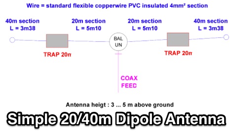 A simple TRAP-dipole project for 20 and 40m bands includes EZNec simulations
 -
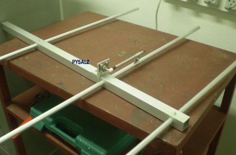 A 3 element yagi antenna project for the 144 MHz band by PY5ALZ in portuguese
 -
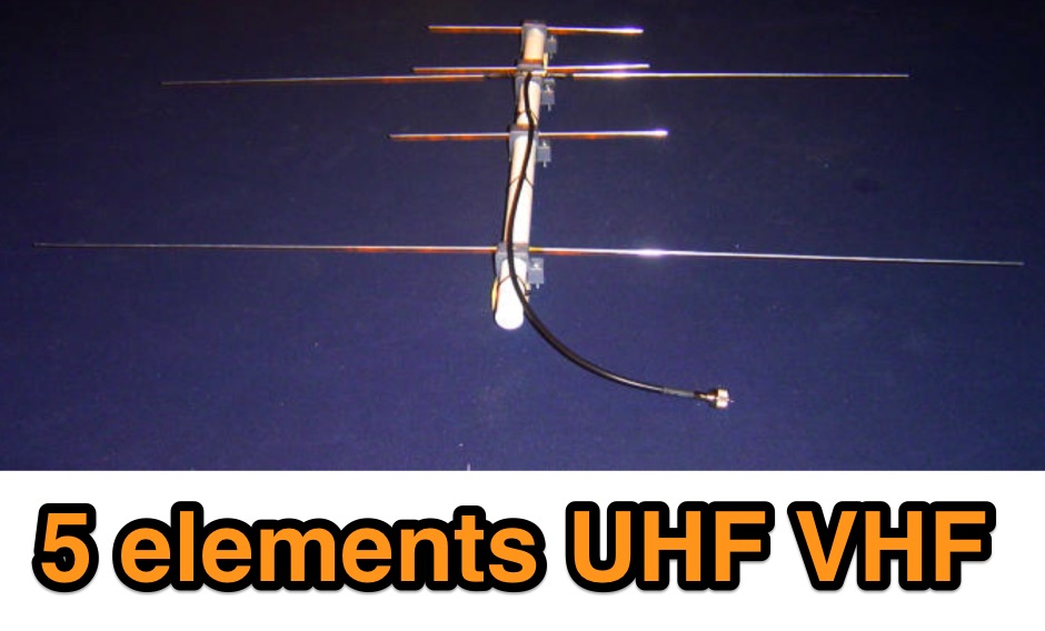 On this page is the design for Dual Band 2M / 70cm antenna with 3.2mm elements. The antenna has a 50 ohm designed driver. This Yagi has a unique element called a Open Sleeve
 -
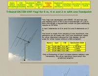 A triband VHF Yagi antenna for 6 m, 4 m and 2 m with one feed-point by DK7ZB
 -
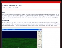
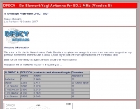 Christoph petermann's df9cy six element yagi antenna for six meter band
 -

-
 A dipole for 2m, 4m, 6m band an hamdwritten note for a homemade vhf antenna that can be tuned across the VHF band
 -
 The document provides a detailed guide on modifying an inverted-L antenna to include the 160 meters band. This enhancement allows amateur radio operators to utilize the lower frequency effectively, which is crucial for long-distance communication, especially during the night. The inverted-L design is popular due to its compact size and ease of installation, making it suitable for various environments. By adding top band capabilities, operators can engage in DXing and contesting on 160m, expanding their operational range and opportunities. The guide includes practical tips and considerations for construction, ensuring that the antenna maintains its performance across the extended frequency range. It discusses the necessary adjustments and materials required for the modification, along with potential challenges and solutions. Whether you are a seasoned operator or a beginner, this project can enhance your station's capabilities, allowing for more versatile operations and improved signal quality on the 160m band.
 -

-
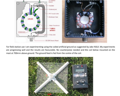 A vertical antenna that can cover HF bands using an UN UN and a fishing pole, usage of tuner is requested.
 -
 A 500-watt mobile antenna project details the conversion of an old 10m hamstick into a highly efficient, multiband "bugstick" for HF operation. The core modification involves replacing the original coil with 25 turns of 6 turns-per-inch, 1.5-inch diameter coil stock, fabricated from #14 wire. This design, intended for a 3-magnet mount on a vehicle cab, achieves resonance on multiple bands by shorting out specific turns on the coil, similar to a **bugcatcher** antenna. Measurements taken with an MFJ-259 analyzer on a GMC pickup show 0 turns shorted for 20 meters (14.2 MHz), 10 turns for 17 meters, 16 turns for 15 meters, 19 turns for 12 meters, and 23 turns for 10 meters. The construction emphasizes using UV-resistant tie-wraps and #14 solid wire with crimp lugs for robust RF connections, bypassing the fiberglass rod for current flow. A bonus section details a 40-meter version, utilizing 48 turns of 8 TPI, 2-inch diameter coil stock.
 -
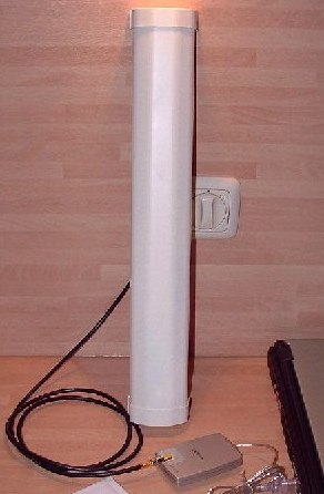
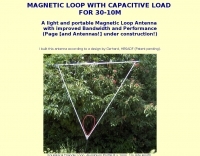 A light and portable magnetic loop antenna with improved bandwidth and performance by HB9MTN
 -
 Construction details and tests about a 2 elements cubical quad antenna for HF Bands (20,17,15,12 and 10m band).
 -
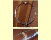 A magnetic loop antenna using a 28\" bicycle rim for six meter band
 -

-
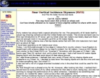 Near Vertical Incidence Skywave (NVIS) and the 40 meter Novice Sub-band.
 -
 An end-fed halfwave antenna for 20 meters band with balun pictures and description by PD7MAA
 -
 Demonstrates the design principles and performance characteristics of **corner reflector antennas**, emphasizing their high gain and directional properties. It covers critical design factors such as the corner angle and the spacing between the radiating dipole and the reflector vertex. The resource explains how reducing the corner angle increases gain but lowers feed impedance, making matching more challenging. Practical angles of 90 degrees or 60 degrees are discussed, with 90 degrees offering easier impedance matching despite slightly lower gain. Details key design considerations, including reflector side length exceeding two wavelengths and reflector width greater than one wavelength for a half-wave radiator. It specifies reflector construction using wire netting, sheet metal, or parallel metal spines spaced less than 0.1 wavelength. The article provides a table with general dimensions for UHF and VHF bands, noting typical impedance values of 50 to 75 ohms and expected SWR of 1.7:1 on the lower band edge. Adjustable radiator-to-vertex spacing is highlighted as crucial for final tuning.
 -
-

-
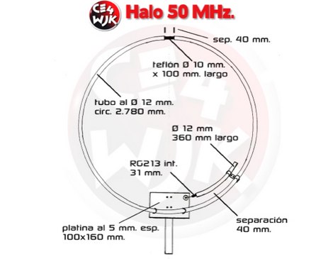
 50 MHz meteor scatter offers a unique opportunity for amateur radio operators to make long-distance QSOs, even when the band appears dead. Meteor scatter involves reflecting radio waves off the ionized trails left by meteors burning up in the upper atmosphere, typically around 105 km high. These trails can facilitate contacts over distances up to approximately 2,300 km. The technique is particularly effective during meteor showers, which increase the number of meteors and thus the chances of successful QSOs. However, random meteors can also be used to achieve contacts, especially on the 50 MHz band, where the longer reflection time compared to 144 MHz makes it easier to work meteor scatter. Operators should be prepared to make QSOs in short bursts, often lasting only a few seconds. The IARU Region 1 meteor scatter procedure recommends using 2.5-minute periods for telegraphy and 1-minute periods for SSB, though shorter periods can be arranged. For 50 MHz SSB, 15-second timing is often used to maximize the chances of completing a contact. The procedure involves specific timing for transmissions based on direction and requires both operators to confirm receipt of callsigns and reports to complete a QSO. Understanding the geometry of meteor scatter, including the optimal radiation angles and the concept of 'hot spots,' is crucial. These hot spots are areas where reflections are most likely to occur, influenced by the Earth's rotation and the path of the meteors. Proper antenna setup, including elevation control and beam direction, can significantly enhance the chances of successful meteor scatter QSOs.
 -
 A lightweight inverted vee antenna that can be supported by a 10 metre long fiberglass squid pole. The antenna is designed to cover 10, 15, 20, 40 and 80 m bands.
 -
-
 Over 1,000 stations in approximately 60 countries were worked using this modified twin-lead folded dipole, demonstrating its effectiveness with just 4 watts on 20 meters. This design, adapted from an ARRL Handbook concept, eliminates the shorting strap found in traditional folded dipoles, simplifying construction while maintaining performance. It utilizes readily available 300-ohm TV antenna feeder ribbon, making it a cost-effective solution for radio amateurs. The antenna's robust construction allows it to handle up to 100 watts without issues, even without a **balun**. The inclusion of a variable trimmer capacitor at the stub provides flexibility for tuning across different frequencies within a band, a practical feature for operators using transceivers like the Icom 735. Formulas are provided to calculate the precise dimensions for any desired operating frequency, enabling customization for various **HF bands**.
 -
 Homebrew a cobwebb antenna for the HF bands. This page describe a cobwebb multiband antenna resonating on 14 18 21 24 and 28 MHz. The cobweb antenna model can be considered a fan dipole, or better, multiple dipoles fed in parallel.
 -
 Choosing a vertical antenna. Buying guide to amateur radio HF vertical antennas by Bencher inc
 -
 An Off-center-feed antenna that covers 80, 40, 20, 17, 15, 12, 10, and 6 meters
 -
 How to build your own beverage antenna for 80-160 meters band by K5ZD
 -
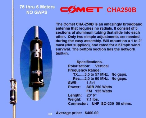 An interesting article by K3DAV comparing the COMET CHA250B to other HF multiband vertical antennas
 -
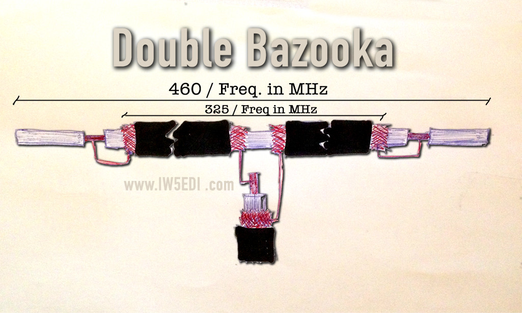 Double Bazooka Antenna, a simple coax based and broad band antenna you can easily build
 -
 A project for a home made 5 element yagi-uda antenna for 2 meters, covering 144-148 MHz band by N1BMX
 -
-
 This 4m Slim Jim Antenna is cheap and easy to build yet it greatly out performs the more usual dipole due to its low angle of radiation. An SWR of 1:1 is obtainable across the 4m ham radio FM band with a simple adjustment.
 -
 A helpful guide to building your own beverage-type low noise receiving antenna for broadband use. Easy, do-it-yourself suggestions to optimize directional performance, even if you lack a farm to put it on.
 -
 An home made Z-Match antenna tuner unit that cover all HF bands between 10 and 160 meters
 -
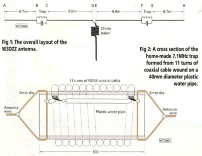 Article published on Practical Wireless about the W3DZZ multiband trapped dipole antenna made available by GM0ONX
 -
 Ham radio antennas and electronics, specialized in 1/2 wave dipole, OCF dipole, windom, full wave loop, end fed, inverted L, portable end fed antenna, long wire, SWL antenna, fan dipole, multiband dipole, G5RV and military antennas.
 -
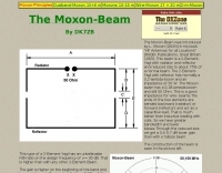 Notes on moxon antennas for VHF and HF bands. Main characteristics, gain and f/b ratio by DK7ZB
 -
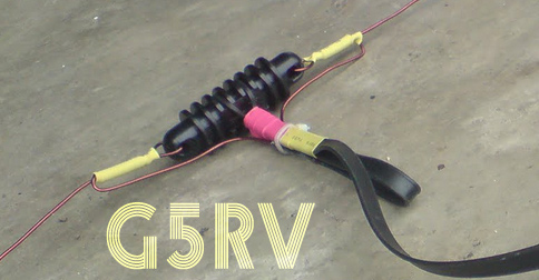 Homebrew G5RV a simple multiband antenna. This article shows detailed pictures of a G5RV home made antenna, including antenna size and dimensions by 9M2ZAK
 -

-
-

-
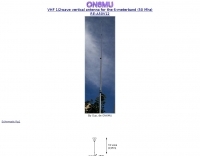
 Building an omnidirectionnal antenna for the 23 cm band, 1240 - 1270 Mhz
 -
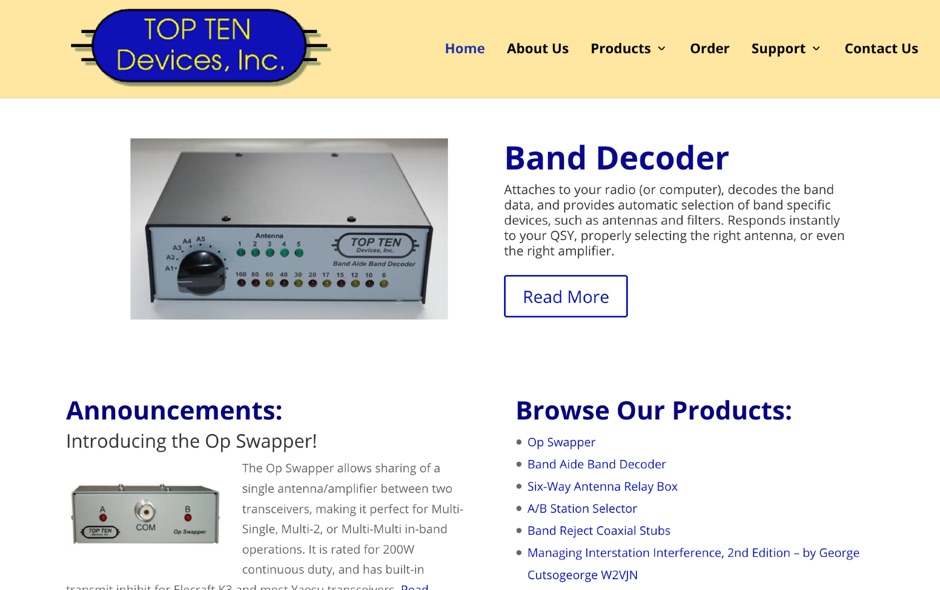 Automatic band decoder, six way antenna relay, band reject coaxial stubs and more. Top Ten Devices is a two-man company formed in 1991 by N3RD and W2VJN.
 -
 This document details the design and construction of a Vinecom 6N4 dual-band Yagi antenna for the 50MHz (6-meter) and 70MHz (4-meter) amateur radio bands. The antenna features 9 total elements (4 elements for 50MHz, 5 elements for 70MHz) on a 4.236-meter aluminum boom. Computer simulations using MMANA software predict 7.21 dBd gain on both bands with front-to-back ratios of 16.01dB (6m) and 15.37dB (4m). The design uses 12.7mm diameter elements mounted on a 32mm square boom, weighing 5.7kg total. Practical measurements with an MFJ-269 analyzer confirmed good SWR performance across both bands after element length adjustments.
 -
 DF9CY experience on a vertical antenna for 40 meter band
 -
 A shortened 160 meters band antenna for hams who do not have 260 ft of space, based on a open-wire-fed short dipoole
 -
 A short dipole wire antenna for 40 meters band. It is a folded dipole that do not make use of coils and can be used either in horizontal or inverted V configuration