Search results
Query: 4 meter antenna
Links: 1193 | Categories: 31
Categories
- Antennas > 20M > 20 meter Dipole Antennas
- Antennas > 20M > 20 meter Vertical Antennas
- Antennas > 20M > 20 meter Yagi antennas
- Antennas > 40M > 40 meter Dipole Antennas
- Antennas > 40M > 40 meter Loop Antennas
- Antennas > 40M > 40 meter Magnetic Loop Antennas
- Antennas > 40M > 40 meter Vertical Antennas
- Antennas > 6M > 6 meter J-Pole Antenna
- Antennas > 6M > 6 meter Yagi Antennas
- Antennas > 40M > 40 meter Delta Loop Antennas
- Antennas > 40M > 40 meter Yagi Antennas
- Antennas > 6M > 6 meter Moxon Antennas
- Manufacturers > Wattmeters
- Antennas > 10M
- Antennas > 12M
- Antennas > 15M
- Antennas > 17M
- Antennas > 20M
- Antennas > 2M
- Antennas > 30M
- Antennas > 40M
- Antennas > 60M
- Antennas > 80M
- Technical Reference > Arduino
- Radio Equipment > HF Vertical Antenna > Cushcraft R8
- Antennas > Halo
- Radio Equipment > HF YAGI Antennas > Hy-Gain TH3JR
- Antennas > Morgain
- Manufacturers > Test Equipment
- Technical Reference > Test Equipment
-
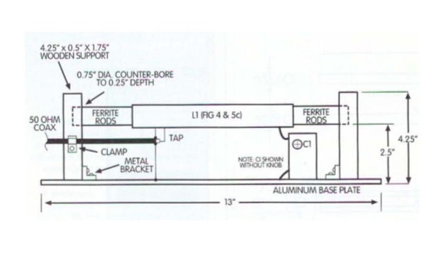 Article from 73 Amateur Radio Today about experimenting on ferrite loops transmitting loop antennas for 80 and 160 meters bands.
 -
-
-
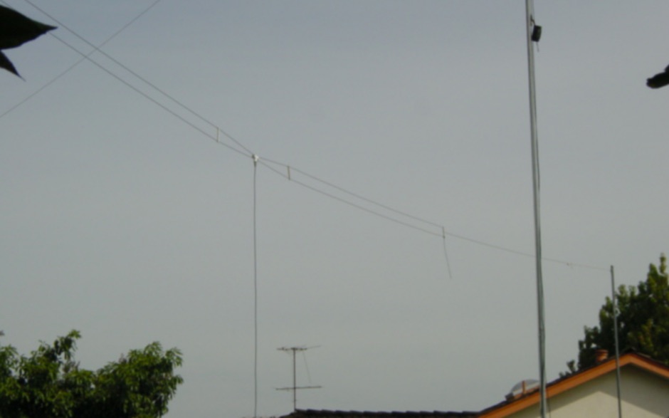 Amateur Radio 40m 20m 15m Half Wave Fan dipole antenna project with part list, pictures and drawing. Includes the option to expand the antenna to cover the 80 meters band
 -
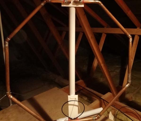 Octagonal magentic loop antennas that work from 20 to 10 meters with pictures and efficiency reports by G1KEA
 -
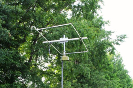 Design and build a 6 meter 2-element Moxon antenna mostly from available aluminum tubing and angle stock.
 -
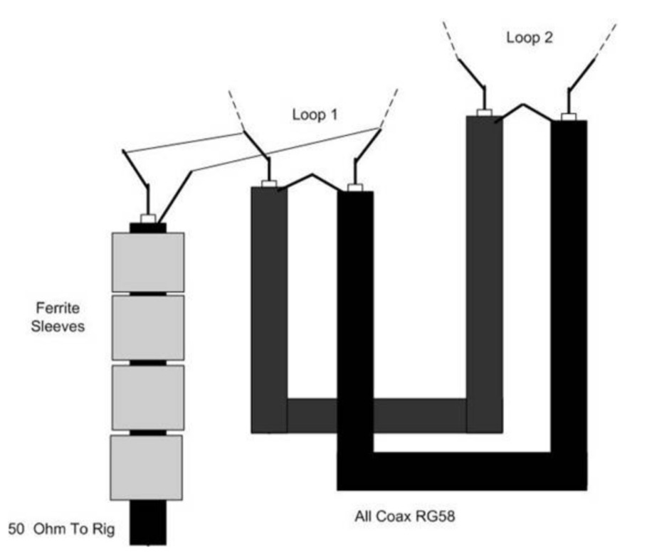 Simple 6 Metre DX Antenna based on an article by LB Cebick in QST May 2002 on a Quad Turnstile antenna. This antenna is basically two full wave loops mounted at right angles fed 90 degrees out of phase to produce an omni-directional horizontally polarized pattern
 -
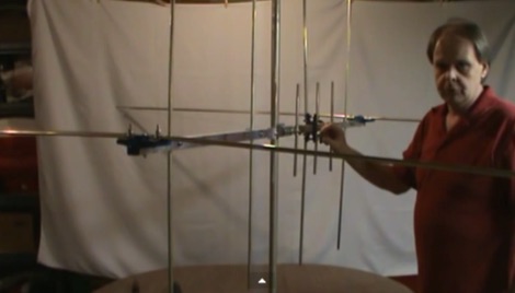 6m/2m/70cm Yagi Antenna Built from Old TV Antenna This turned out to be a great little antenna. It works the 6 meter, 2 meter and 70 centimeter bands. You can use one common feedpoint or two seperate feedpoints depending on how you would like to connect this antenna to your transceiver.
 -
 Home made wire dipole on a lenght of 30 meter 98.4 ft by PE1OPM
 -
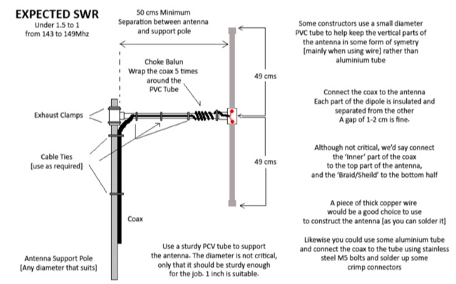 This article serves as a beginner-friendly guide to constructing a simple VHF dipole antenna for 2 meters, perfect for novices in the hobby. With an emphasis on affordability and simplicity, it explains the basics without overwhelming technical details. Recommendations for coaxial cable and mounting methods are provided, offering practical solutions for effective communication. By following these instructions, novices can build a functional antenna without breaking the bank.
 -
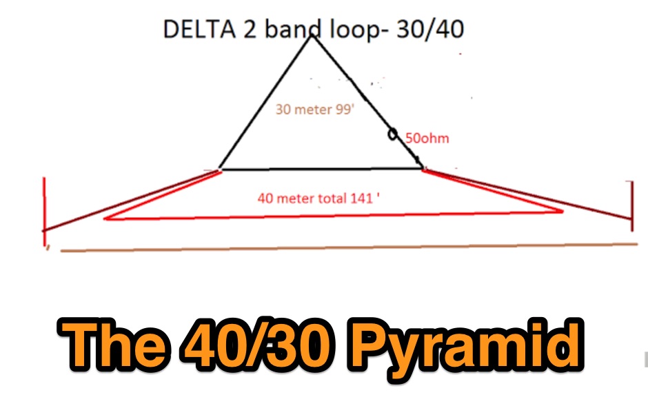 A dual band delta loop antenna resonating on 30 and 40 meters band using a single wire for the top slopers on both 30 and 40 meters and does not need any balun
 -
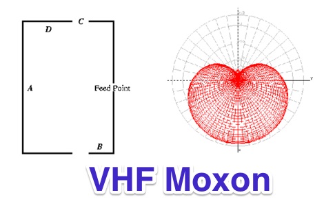 Constructing a 2-meter Moxon antenna for MURS channels, this resource details the antenna's geometry and expected radiation pattern. The design, optimized for low SWR, high gain, and front-to-back ratio on the first three MURS channels, uses 1/8-inch bronze brazing rod for elements. Author John E. Davis provides specific geometric parameters (A, B, C, D dimensions) rounded to the nearest 16th of an inch, along with a link to the final _.nec_ file for further analysis. Performance results show the attic-mounted Moxon performs well on the 2-meter band, despite its MURS optimization, with measured SWR plots provided. NEC-2 modeling predicts over 6 dBi gain and 40 dBi front-to-back ratio in free space. The author compares its directional performance to a _J-pole_ antenna, demonstrating substantially better signal strength for a nearby repeater when the Moxon is pointed in its general direction, confirming its superior gain and directivity.
 -
 Presents Eagle Stainless Tube & Fabrication as a certified distributor specializing in various tubing products essential for antenna construction and other amateur radio projects. It details their offerings, which include aluminum tubes in fractional, metric, and heavy wall specifications, alongside stainless steel bar stock in round, square, and flat profiles. The resource highlights the availability of a diameter sizing chart and direct contact options for specialists, indicating a focus on providing specific material dimensions and expert support for custom fabrication needs. The company emphasizes its role as a supplier of raw materials, crucial for hams engaged in DIY antenna builds or structural components for their shacks. Their inventory supports the precise mechanical requirements often encountered in radio frequency engineering, where material strength, weight, and corrosion resistance are critical design factors for outdoor installations. The site primarily serves as a product catalog and contact point for sourcing specialized metal tubing and bar stock, providing technical specifications and material grades relevant to robust amateur radio infrastructure.
 -
 Demonstrates the principles of effective HF multi-band antenna systems, emphasizing the use of non-resonant antennas, understanding line attenuation, and the proper application of transmatches and baluns. The resource challenges prevalent amateur radio myths, such as the necessity of a 1:1 SWR at the antenna feedpoint and the misconception that reflected power is lost or damages equipment. It cites authorities like Jim Fisk (Ham Radio Magazine) and M. Walter Maxwell (W2U, QST's "Another Look At Reflections" series) to support its arguments, providing historical context and technical explanations for these long-held beliefs. The article details how to combine non-resonant antennas with appropriate feedlines and matching devices to achieve broad-band operation. It compares coaxial cable losses with those of balanced open-wire lines, illustrating how ladder line can significantly reduce attenuation and handle higher impedances, enabling an 80-meter dipole to operate effectively across multiple HF bands. Practical guidance is offered on transmatch operation, explaining impedance matching principles and debunking the idea that tuners merely "fool" the transmitter. It also clarifies the function and potential misapplication of baluns, particularly transformer-type baluns, in the presence of high SWR.
 -
 Local amateur radio clubs often serve as vital hubs for hams to connect, share knowledge, and participate in group activities. The Orleans County Amateur Radio Club (OCARC), operating under the callsign WA2DQL, provides a focal point for amateur radio operators in Albion, New York, and the surrounding Orleans County area. These organizations frequently host events, offer technical assistance, and foster camaraderie among members, supporting various aspects of the hobby from contesting to emergency communications. OCARC's activities include discussions on proposed Technician class privileges for **80, 40, and 15 meters**, indicating an interest in regulatory changes affecting entry-level licensees. The club also promotes the use of online tools like _Radio Mobile Online_ for antenna pattern analysis and _VOACAP Online_ for propagation predictions, aiding members in optimizing their station performance. Furthermore, OCARC highlights participation in _Parks On The Air_ (POTA) events, such as the Erie Canal Bicentennial Celebration in 2025, encouraging outdoor operations and public engagement with amateur radio.
 -
 This resource details the construction of a Moxon rectangle antenna, a two-element wire beam, drawing inspiration from a _QST_ article by Allen Baker, KG4JJH, and a project group led by KD6WD. It outlines the use of _AC6LA_ software for critical measurements (A-E) to design the antenna for specific bands like 17 meters, emphasizing the simplicity of adjusting frequency and wire size. The guide covers material selection for spreaders, such as telescoping fiberglass fishing poles, and various hub constructions, including aluminum tubing and PVC joints, with accompanying images. The author shares practical insights from building multiple Moxons for 10, 15, 17, and 20 meters, noting consistent 1:1 SWR at design frequencies and broadbanded performance. It describes the feedpoint assembly using a 1:1 Yagi current balun and wire nuts for robust, adjustable connections. The resource also discusses element insulators made from Lucite strips and attachment methods to spreaders using plastic wire ties and duct tape, ensuring precise element spacing. Performance observations include significant signal improvements (4-5 S units) over quad loops and a unique "DX-Vane" effect where the suspended antenna self-aligns with the strongest DX signal. The author also recounts an unsuccessful attempt at a dual-band 17/20 meter Moxon, concluding that the Moxon is inherently a monoband antenna, supported by _EZNEC_ plots for a 17-meter design.
 -
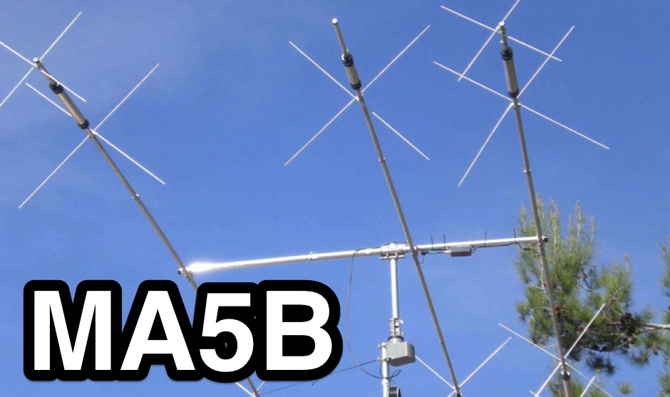 Cushcraft MA5B 20 / 17 / 15 / 12 / 10 Meter Beam Antenna assembly and installation manual
 -
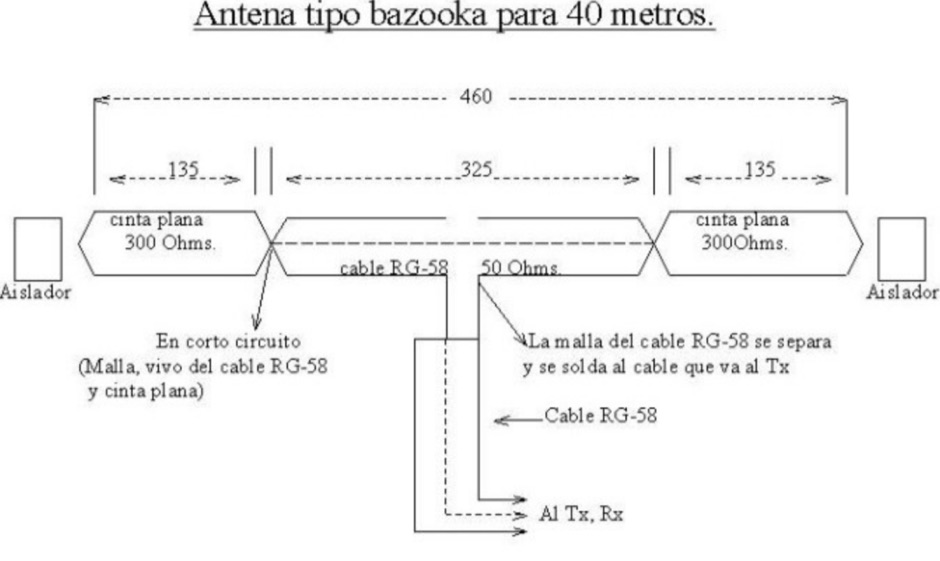 A bazooka coax antenna for 40 meters band design by CA6TYS
 -
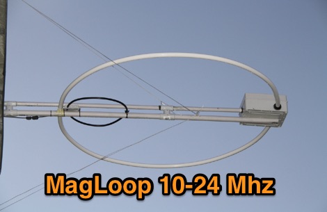 A few pictures of an homebrew magnetic loop RTX antenna project, working from 30 to 12 meters with excellent results
 -
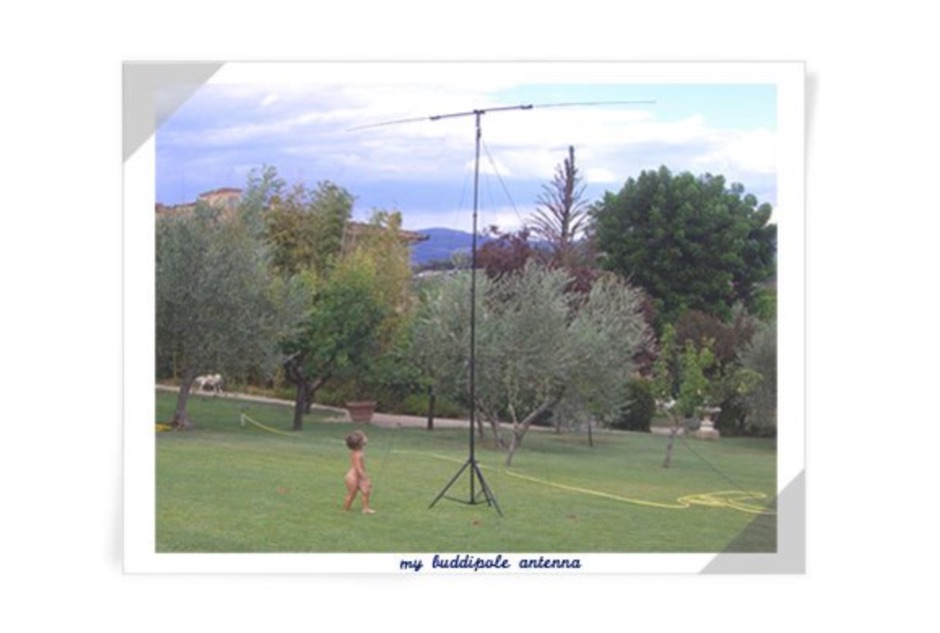 The Buddipole Deluxe, a portable HF/VHF antenna system, receives a practical assessment from IW5EDI after a month of field use. The author, constrained by antenna restrictions, highlights the system's crucial role in enabling portable operations, even managing sporadic digital activity from a balcony. Direct comparisons to a fixed 3-band dipole reveal surprisingly comparable signal reports on 15, 17, and 20 meters, underscoring the Buddipole's effectiveness in real-world scenarios. Tuning the Buddipole proves straightforward on bands down to 20 meters, though the review notes significant challenges with SWR on lower bands like 40 meters, where achieving better than 3:1 SWR was problematic. Observations also include SWR variations with dipole rotation and mast height, suggesting environmental factors play a role. The overall manufacturing quality of the antenna and its accessories, including the tripod and carry bag, is deemed good, despite a minor issue with a pole connector. Looking ahead, the author plans to construct a homemade Buddipole version, possibly optimized for the 30-meter band, specifically for PSK31 operations from an apartment. This personal project reflects a common amateur radio practice of adapting commercial designs for specific needs, further extending the utility of portable antenna concepts.
 -
 Operating the _Icom IC-746_ HF/VHF transceiver often presents specific technical questions, and this resource compiles a comprehensive Frequently Asked Questions (FAQ) document in an ASCII text format. It details common inquiries and solutions related to the rig's functionality, accessories, and potential modifications. The content is structured into distinct sections addressing general information, power supplies, antennas, microphones, keyers, amplifiers, TNC integration, and optional IF filters. The FAQ provides practical guidance on topics such as configuring the internal automatic antenna tuning unit (ATU), selecting appropriate power supplies, and understanding microphone pin-outs. It also delves into advanced subjects like computer control via CI-V, wiring for PSK31 operation, and troubleshooting common issues like low S-meter readings on 2m FM or loose tuning shafts. Specific questions cover the installation of optional IF filters, comparing Inrad versus Icom filters, and optimizing filter combinations for various modes. Furthermore, the document outlines various hardware and firmware modifications, including those for increasing monitor volume, replacing LCD driver transistors, and implementing a "poor man's TCXO." It even touches upon untested modifications, such as replacing PIN diodes in the demodulator. The FAQ also lists manual errata and discrepancies, offering a robust knowledge base for IC-746 owners seeking to optimize their station or resolve operational challenges.
 -
 The W6NL Moxon Yagi is a high-efficiency two-element 40m Yagi that uses cross elements to provide both loading and Moxon coupling, addressing the challenge of deploying a directional antenna on the 40-meter band. This resource details the transformation of a _Cushcraft XM240_ Yagi into this Moxon configuration, replacing the original loading coil LCA sections with four new assemblies. The guide provides comprehensive instructions for building the boom and elements, including specific dimensions for new sections and tee loading elements, along with detailed drawings and a full parts list for the conversion. Performance data indicates the converted antenna achieves **10.73 dBi** gain at 7.050 MHz with 99.5% efficiency and a high front-to-back ratio. The VSWR bandwidth is over **300 kHz**, ensuring good performance across a significant portion of the 40m band. Construction involves reinforcing element sections, attaching tee loading elements with U-bolts, and implementing element guying using materials like _Phillystran_ to manage sag and maintain structural integrity.
 -
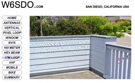 An almost invisible wire antenna for the 17 meters band
 -

-
-
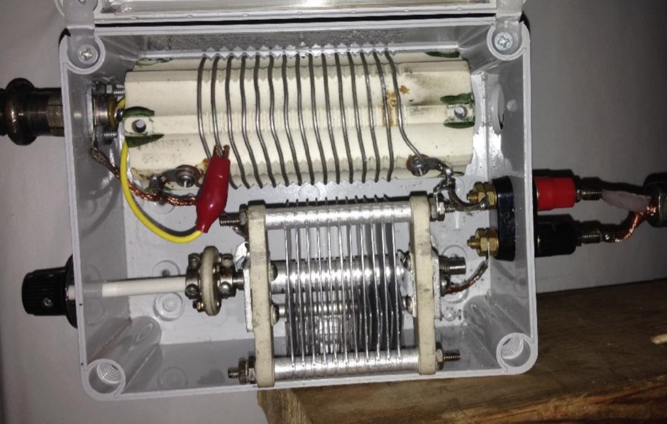 The page provides detailed instructions on how to build a 60 meter End Fed Half Wave Antenna Tuner, with large pictures and diagrams. It is aimed at amateur radio operators looking to construct their own antennas for the 60 meter band.
 -
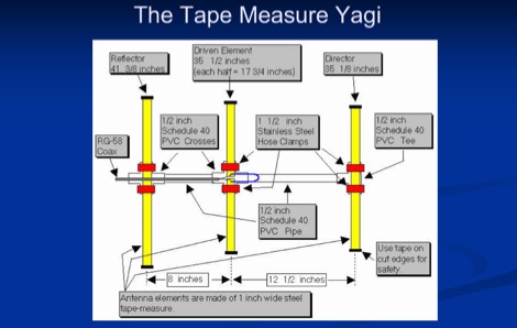 A presentation of the Yagi Antennas, and other interesting tid-bits by Brian Mileshosky. The document provides an in-depth exploration of the Yagi-Uda antenna, detailing its historical development, design principles, and performance characteristics. Originally described in the 1920s, the Yagi antenna features a driven element and parasitic elements, including reflectors and directors, which collectively determine its behavior. The document highlights how element lengths, diameters, and spacing influence gain, impedance, and directivity. It also discusses the antenna's reciprocal nature and presents data on typical gain values for various element configurations. Additionally, the text covers practical considerations, such as the construction of a "Tape Measure Yagi" for amateur use, and touches on related antenna types like dipoles and their application in Near Vertical Incident Skywave (NVIS) communication.
 -
-
 Stryker 10 Meter Amateur Radio trasceivers, antennas and accessories manufacturer
 -
 KD5FX, 20 through 6 meters, QRP to full legal power, lightweight, easy to carry
 -
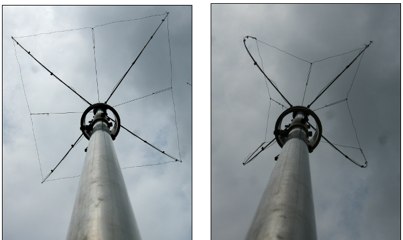 An HF vertical antenna by N3OX with a flexible capacitance hat
 -
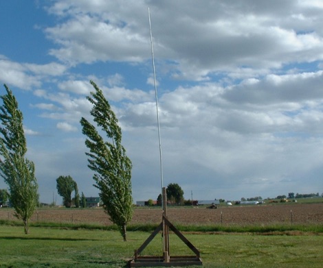 Homebrew 30 meter full quarter wave vertical antenna.
 -
 The M0PLK multiband delta loop antenna project details the construction of a non-resonant, bidirectional antenna designed for 20-10m operation, requiring an external antenna tuner. The design utilizes two 5.65m aluminum tubes arranged at right angles, with 2x 2.80m antenna wires converging into a 2.30m ladder line, feeding a 1:4 balun. The resource provides a comprehensive parts list, including specific dimensions for aluminum tubes (25mm, 20mm, 16mm outer diameter), DX-Wire FS2, and custom 3D-printed components like a middle insulator, tube end caps, and ladder line spacers, with STL files provided. Construction steps cover base plate fabrication from a 300x300x4mm aluminum sheet, balun assembly, tube preparation with slits and threaded holes, and wire attachment with strain relief. Initial VSWR measurements are presented, indicating performance in line with expectations across the target bands. The author reports successful SSB test QSOs to the USA on 10, 12, 15, 17, and 20m immediately after completion. The project highlights the antenna's bidirectional pattern, noting the need for a lightweight, remote-controlled rotator to fully utilize its directional capabilities. Comparisons are drawn to the Cobweb antenna, with the M0PLK design cited for its reduced local QRM pickup. The article references external sources, including M0AWS's detailed report and PC modeling, along with other construction variants and commercial assembly instructions, providing a robust foundation for replication.
 -
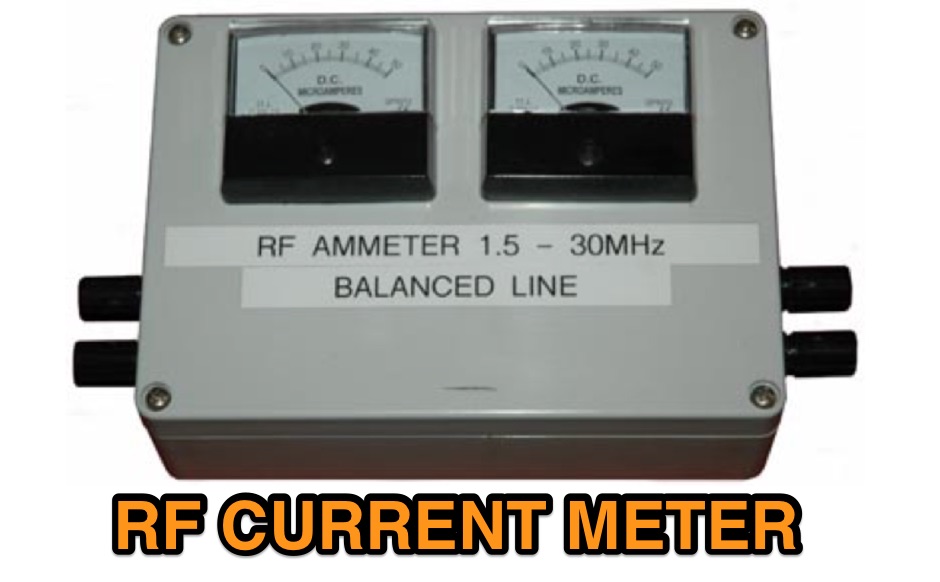 This R.F. current meter was developed to assist in measuring line currents in balance feed lines as used in the All Band HF Antenna.
 -
 KB9AMG's Top WSPR Spots presents a focused online tool for monitoring **2-way WSPR reports**, specifically detailing propagation data from February 2026 through March 2026. This resource aggregates _WSPRnet_ data, allowing radio amateurs to observe weak signal propagation conditions across various bands. The interface is straightforward, presenting callsigns, frequencies, signal-to-noise ratios, and distances for each reported contact, which is crucial for understanding current band openings and signal paths. The utility of this WSPR spotter lies in its ability to quickly visualize global propagation. Users can identify active stations and assess signal viability over long distances, with reports often showing contacts spanning thousands of kilometers. For instance, a typical WSPR report might indicate a signal from Europe reaching North America with a _SNR_ of -25 dB, demonstrating effective low-power communication. This data is invaluable for planning DX operations or evaluating antenna performance under actual propagation conditions.
 -
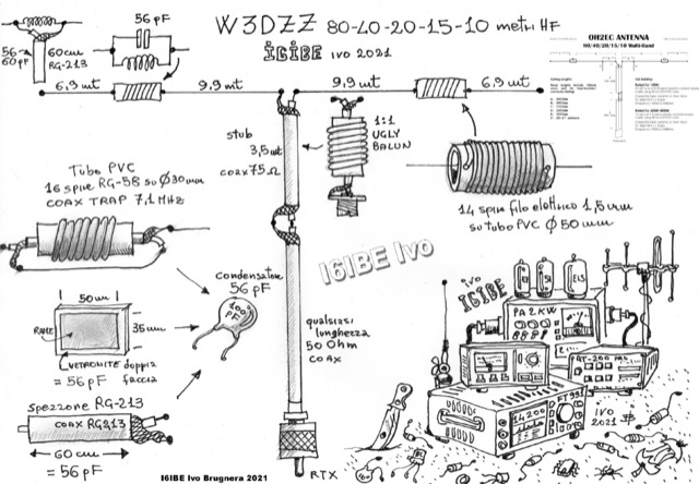 An easy to build and extremely high performance antenna, works perfectly on all HF bands 3.5-28 MHz with some compromises, it is basically an half wave dipole for 40-80 meters, an LC circuit or trap 40 meters allows you to use a single radiating element.
 -
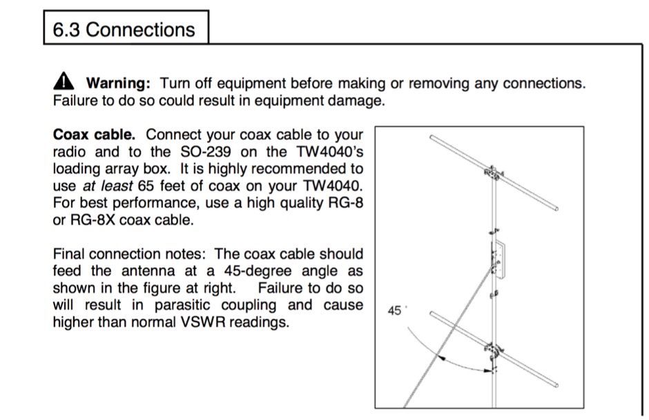 The TransWorld Antennas TW4040 The Adventurer Monobander™ is a portable HF antenna designed for rapid deployment in field operations, including **SOTA** and **POTA** activations. This manual details the antenna's assembly, tuning procedures, and operational guidelines for optimal performance on the 40-meter band. It outlines the specific components, such as the telescoping whip and base unit, required for proper setup. Instructions cover mast erection, radial wire deployment, and impedance matching to achieve a low **VSWR** across the designated frequency segment. The document also provides guidance on antenna orientation and environmental considerations for portable use. It specifies the antenna's power handling capabilities and physical dimensions when fully deployed and collapsed for transport.
 -
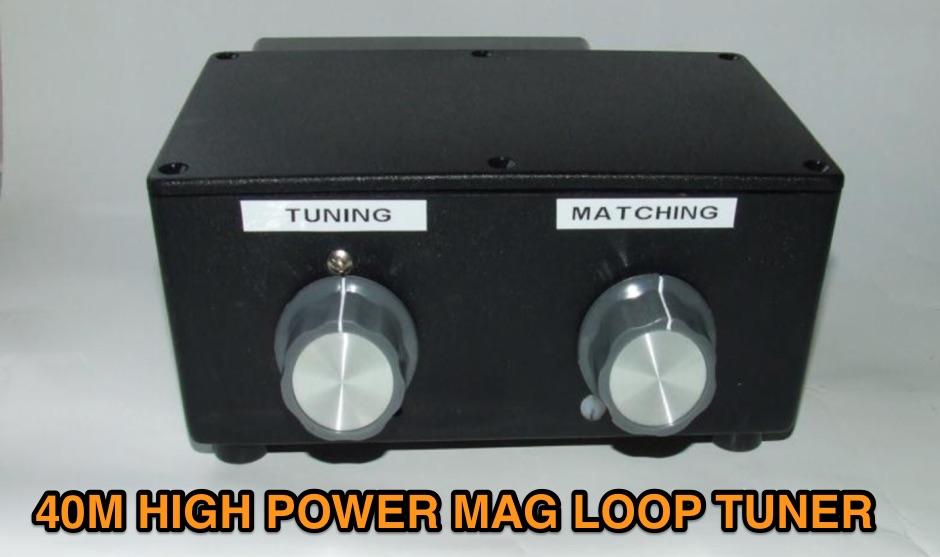 A dual band portable inverted V antenna for 80 and 40 meters band with dimensions for other bands and several assembling instruction
 -
 Constructing a compact directional antenna for the 17-meter band, this resource details the build process for a Moxon rectangle, a two-element Yagi variant with folded-back elements. It covers the antenna's evolution from the _VK2ABQ beam_ and provides specific dimensions for a version built using fishing pole whips. The content includes a discussion of the antenna's radiation pattern, feedpoint impedance, and its inherent front-to-back ratio, which is often superior to a standard two-element Yagi. Practical considerations for element spacing and material choices are also addressed, alongside a visual representation of the antenna's physical layout. Performance data presented includes a comparison showing the Moxon rectangle's **2.5 dB gain** over a half-wave dipole and a front-to-back ratio of **20 dB**. The resource also touches upon the antenna's relatively wide bandwidth for a two-element beam and its suitability for portable operations due to its compact footprint. It offers insights into optimizing the design for specific operating conditions and discusses the advantages of its lower take-off angle compared to omnidirectional wire antennas, making it effective for DX contacts on the 17-meter band.
 -
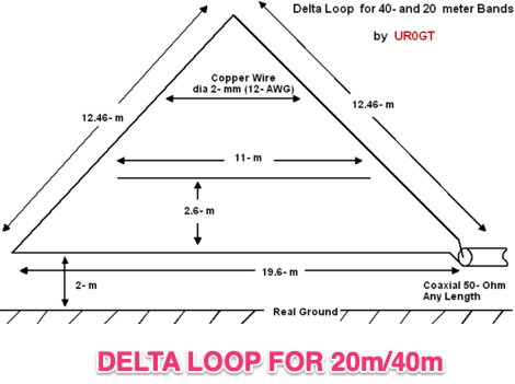 This wire antenna for 40 and 20 meter band feature a good SWR. Horizontal side of the antenna is placed at two meters above the ground. Impedance of the antenna are depending by the height of the base from the ground and conditions of the ground
 -
 Constructing a directional antenna for the 6-meter band (50 MHz) can significantly improve signal strength and reduce QRM during local ragchews or **Field Day** operations. This project details the assembly of a Moxon rectangle antenna, known for its compact size and respectable gain, making it a practical choice for portable or fixed station use on the magic band. The design utilizes readily available materials such as 14 AWG copper wire for the radiating elements and PVC pipe for the frame, ensuring an inexpensive build. The article provides specific dimensions and construction steps, allowing radio amateurs to replicate the antenna with confidence. It emphasizes achieving a low **SWR** across a bandwidth exceeding 1 MHz, crucial for efficient power transfer from the transceiver. Performance characteristics include a reported 5.5 dBi gain and a front-to-back ratio of 20 dB, offering effective directivity. The project also highlights the antenna's suitability for Field Day, where quick deployment and reliable performance are paramount for maximizing contacts.
 -
 The Superantennas MP-1 portable HF antenna is analyzed for its design and field performance, particularly its high-Q loading coil and 3/8-inch mounting. The review details the antenna's construction, including an 8-inch vertical section, a large-diameter loading coil tuned by a sleeve, and a 4-foot whip that disassembles into six rods for transport. Initial testing with the supplied 10-foot ribbon cable "ground plane" yielded poor SWR and RF hot conditions, indicating an inadequate ground system. Further experimentation with longer radials and resonant counterpoises for each band improved matching and eliminated RF hot issues, but introduced significant operational complexity. The author notes the difficulty in optimizing both counterpoise length and coil setting without an antenna analyzer, and the sensitivity of the MP-1 to counterpoise deployment. The review also discusses the recommendation to tune for maximum received signals rather than minimum SWR, often necessitating an external ATU due to the antenna's typical low impedance. The **MP-1**'s critical dependence on resonant counterpoises for effective operation, especially when elevated, is highlighted as a major drawback for portable use. The author ultimately sold the antenna, concluding that despite its sound technical design, its fussy nature and the need for extensive counterpoise management or an ATU detract from its portability and convenience compared to simpler, less expensive dipole solutions. The **Superantennas MP-1** is deemed a flawed portable antenna, requiring considerable effort to achieve its claimed performance.
 -
 The 160-meter amateur radio band, spanning 1.8 to 2 MHz, was historically the lowest frequency amateur allocation until the introduction of the 630-meter and 2200-meter bands. ITU Region 1 allocates 1.81–2 MHz, while other regions use 1.8–2 MHz. This band, often called "Top Band" or "Gentleman's Band," was established by the International Radiotelegraph Conference in Washington, D.C., on October 4, 1927, with an initial allocation of 1.715–2 MHz. Effective operation on 160 meters presents significant challenges due to the large antenna sizes required; a quarter-wavelength monopole is over 130 feet, and horizontal dipoles need similar heights. Propagation is typically local during the day, but long-distance contacts are common at night, especially around sunrise and sunset, and during solar minimums. The band experienced a resurgence after the LORAN-A system was phased out in North America in December 1980, leading to the removal of power restrictions.
 -
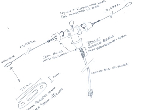 A simple drawing schematic of a portable field dipole for 14 MHz with dimensions in meters and instruction for setting up the antenna and to store the radial for easy transportation
 -
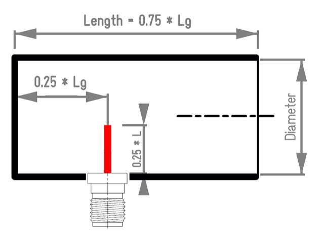 Aka Circular Waveguide Antenna. This online antenna calculator let you plan your cantenna for the desired frequency of operation, giving the Can diameter you have available.
 -
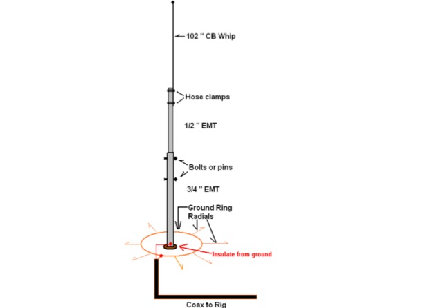 A simple, cheap and easy to build 26 feet long vertical antenna that works DX on 20 - 10 meters including WARC Bands, it is designed for portability for field days, camping, or permanent installation, cost, and to achieve at least 1/2 wavelength on the WARC bands.
 -
 A review of all possible receiving antennas for top band 160 meters
 -
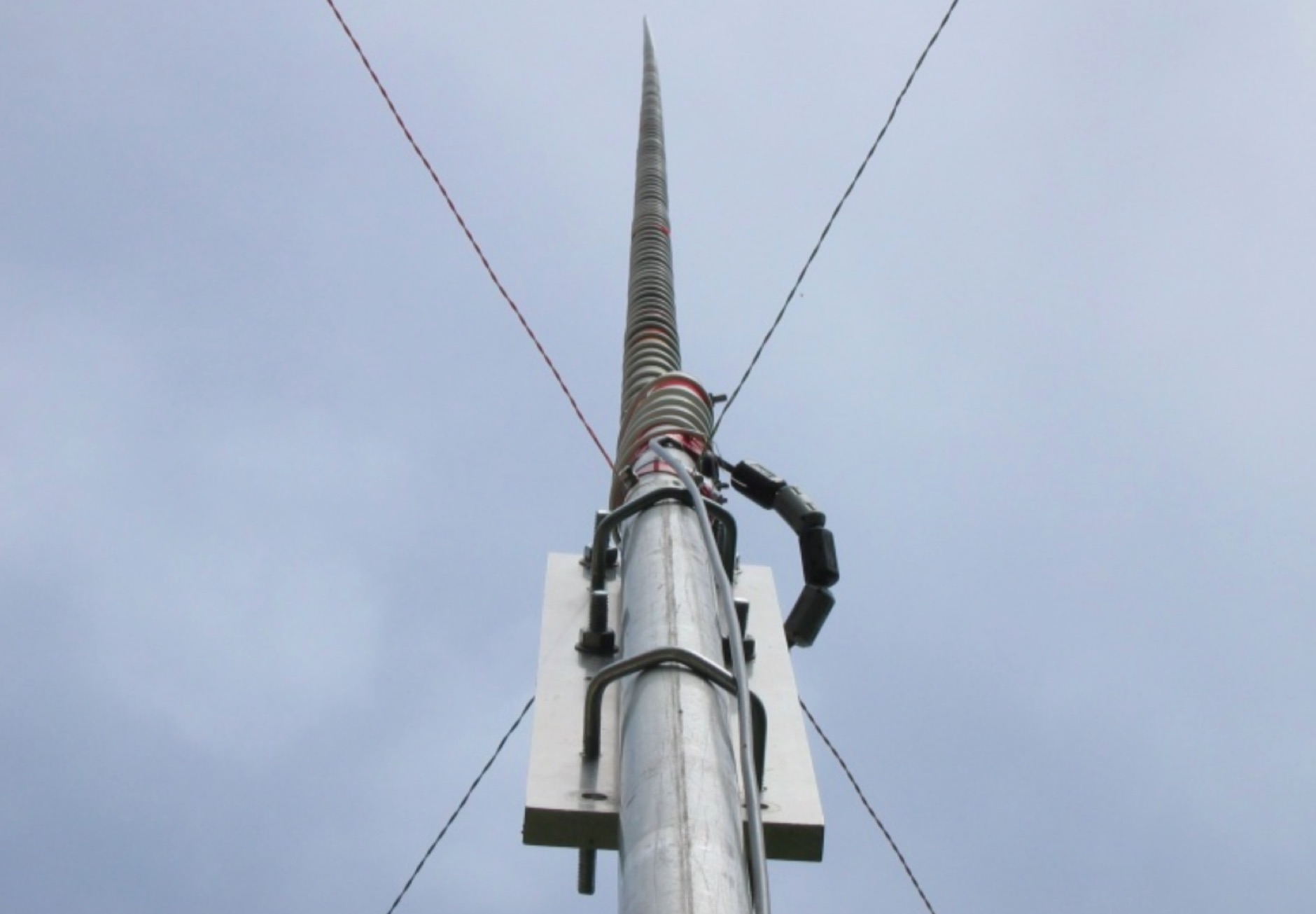 A helically wound vertical antenna experiment. 14 meter of wire wounded on a 8 meter fishing pole with 4 elevated radials
 -
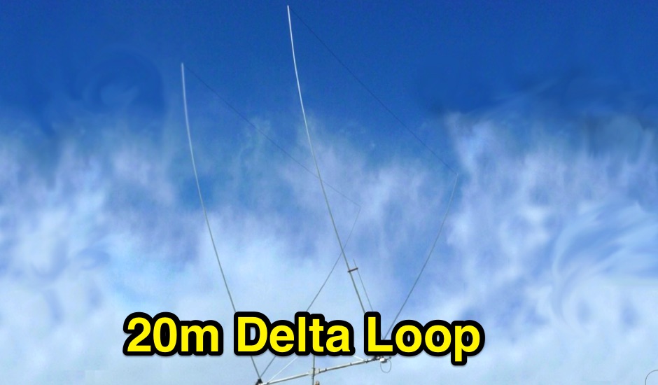 A delta loop antenna for 20 meters band designed with MMana with a tuning system made in a classic stub configuration
 -
 The article, "Using 75 Ohm CATV Coaxial Cable," details methods for employing readily available 75-ohm CATV hardline in standard 50-ohm amateur radio setups. It addresses the inherent impedance mismatch and practical considerations, such as connector compatibility, for hams seeking cost-effective, low-loss feedline solutions. The resource specifically contrasts common 50-ohm cables like RG-8, RG213, and _LMR-400_ with 75-ohm hardline, highlighting the latter's lower loss characteristics, particularly at VHF and UHF frequencies. It explores two primary approaches to manage the impedance difference: direct connection with an acceptable SWR compromise and precise impedance transformation. The direct connection method acknowledges that a perfect 1:1 SWR is not always critical, especially when using low-loss coax. For impedance transformation, the article explains the use of half-wavelength sections of coax to reflect the antenna's 50-ohm impedance back to the transmitter, noting its single-frequency effectiveness. It also briefly mentions transformer designs using toroid cores and a technique involving two 1/12 wavelength sections of feedline for broader bandwidth. The content further clarifies the concept of _velocity factor_ for calculating electrical versus physical cable lengths, providing a generic formula for precise length determination. It notes that while half-wave matching is practical for 10 meters and above, it can result in excessively long runs for lower bands like 160 meters, potentially adding **250 feet** of cable. The article also mentions achieving a usable bandwidth of 28.000 MHz up to at least **28.8 MHz** on 10 meters with specific transformation techniques.