Search results
Query: am band antenna
Links: 666 | Categories: 26
Categories
- Antennas > 6M > 6 meter J-Pole Antenna
- Antennas > HexBeam
- Radio Equipment > HF Vertical Antenna
- Manufacturers > Antennas > VHF UHF Microwave > HT Antennas
- Manufacturers > Antennas > VHF UHF Microwave > Mobile Antennas
- Manufacturers > Antennas > VHF UHF Microwave > Quad Antennas
- Manufacturers > Antennas > VHF UHF Microwave > Satellite antennas
- Manufacturers > Antennas > HF > Mobile Antennas > Screwdriver Antennas
- Manufacturers > Antennas > VHF UHF Microwave > Vertical Antennas
- Antennas > 23cm
- Antennas > 2M
- Antennas > 30M
- Antennas > 4M
- Antennas > 60M
- Antennas > CobWebb
- Radio Equipment > Contest Hardware
- Antennas > End-Fed
- Antennas > G5RV
- Antennas > Halo
- Antennas > HB9CV
- Antennas > Indoor
- Antennas > Maria Maluca
- Operating Modes > Microwave
- Antennas > Moxon
- Antennas > Resonant Feedline Dipole
- Antennas > Spiral
-
 This is a vertical multiband antenna made up of several aerial elements lambda/4 length, feeded with just a coaxial cable in French.
 -
 Determining the actual need for an antenna tuner often hinges on the specific antenna and feed line configuration in use. While many hams believe a tuner is always essential, its primary role is to present a 50-ohm impedance to the transceiver, not to "tune" the antenna itself. For instance, a resonant dipole fed with _coaxial cable_ at its design frequency typically requires no tuner, as the feed line impedance closely matches the radio's output. However, operating a non-resonant antenna, or using a resonant antenna on multiple bands, frequently necessitates a tuner to manage high Standing Wave Ratio (SWR) on the feed line. The article clarifies that a tuner placed at the transceiver only matches the radio to the feed line, not the antenna to the feed line. For maximum efficiency with a non-resonant antenna, an _automatic antenna tuner_ (ATU) or a remote tuner placed at the antenna feed point is often more effective, minimizing losses in the feed line. The discussion also touches on the practical implications of SWR, noting that modern transceivers often fold back power at high SWR, making a tuner a practical necessity to achieve full output power, even if the antenna itself is not perfectly matched.
 -
 The project details a DIY SWR/Wattmeter designed around an _Arduino Uno_ shield, providing capabilities to measure RF power from 2 to **200 watts** and Standing Wave Ratio (SWR) for HF amateur radio bands. This construction features a compact design, integrating the measurement circuitry directly onto a custom PCB that interfaces with the Arduino Uno microcontroller. Key components include a directional coupler for sensing forward and reflected power, precision rectifiers, and analog-to-digital conversion for processing RF signals. The Arduino firmware handles calibration, calculations, and displays the results on an integrated LCD, offering real-time feedback on antenna system performance. The design prioritizes simplicity for homebrewers. Performance specifications indicate accurate readings within the **2-200W** power range, suitable for typical QRP to medium-power HF operations. The project provides schematics and a basic overview of the software logic.
 -
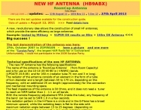 A new, revolutionary design allows the construction of small HF antennas, which provide the same efficiency as large antennas. This antenna can be built for all HF bands, from 10 to 80 m.
 -
 This Vertical antenna design by David Reid for lower bands focuses on achieving effective DX communication by optimizing the antenna low-angle radiation for long-distance contacts. The design incorporates techniques like linear loading and capacity hats to reduce the antenna's height while maintaining performance, especially on 40m and 80m bands. Building a solid ground plane and using quality materials ensure efficiency and durability. Although vertical antennas can be complex to build, this project simplifies the process, making it accessible for ham operators seeking strong, reliable signals.
 -
 Here's an award-winning, easy-to-homebrew, multi-band portable vertical antenna designed by long-time antenna aficionado James Bennett, KA5DVS. He documented the design and construction plans for a portable antenna that can be built with relatively ordinary components
 -
 K9AY loop antenna installed at PA6Z Contest group. This is a receiving antennas for the low bands (160m, 80m and 40m). Include schematics and info on a building the control box, preamplifier and low-pass filter
 -
 Details the construction and optimization of antenna systems for amateur radio satellite operations, focusing on practical, homebrew solutions for VHF/UHF bands. It covers building _groundplane antennas_ from salvaged materials, recycling old beam antennas into new configurations like a 2-meter crossed yagi, and constructing a 10-meter horizontal delta loop. The resource also explains antenna matching techniques, including folded dipole driven elements and quarter-wave transformers, along with the importance of accurate SWR measurements and minimizing coax loss. Demonstrates how to achieve a **1:1 SWR** by carefully trimming elements and adjusting radial angles on groundplane antennas. It provides insights into selecting appropriate coax and connectors, highlighting the benefits of Belden 9913 for low loss and the proper installation of _N-connectors_. The article also addresses RFI mitigation from computer birdies and presents a design for a silent triac antenna control circuit, offering practical solutions for common satellite station challenges.
 -
 Antenna suitable for all the HF amateur bands, including the so called WARC bands by vk6ysf
 -
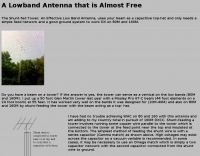 The Shunt-fed Tower, an effective Low Band Antenna, uses your beam as a capacitive top-hat and only needs a simple feed network and a good ground system to work DX on 80M and 160M.
 -
 Presents a practical design for a **crossed-dipole turnstile antenna** specifically engineered for 2-meter Amateur Radio Direction Finding (ARDF) events. The author, WB6RDV, details a robust, omnidirectional, horizontally-polarized antenna, addressing the international ARDF rules requiring such characteristics at a height of two to three meters above ground. This contrasts with the vertical polarization often used in Southern California, highlighting the design's adherence to specific event requirements. The electrical design employs a classic crossed-dipole with a 75-ohm phasing section, resulting in a slight impedance mismatch and an SWR of approximately 1.3:1 with a 50-ohm feedline. Construction utilizes readily available and inexpensive PVC plumbing components and 1/8-inch bronze welding rod for elements. The guide provides step-by-step instructions for mechanical assembly, including drilling element holes at precise 90-degree spacing and preparing the RG-179 matching section. WB6RDV shares insights from his own build experience, discussing the use of plated brass versus aluminum spacers for element attachment and the effectiveness of crimping as an alternative to soldering. The document also covers final assembly, including the integration of ferrite beads as a choke balun and options for weatherproofing and alternative mounting configurations, emphasizing the adaptability of the design for other VHF bands through scaling.
 -
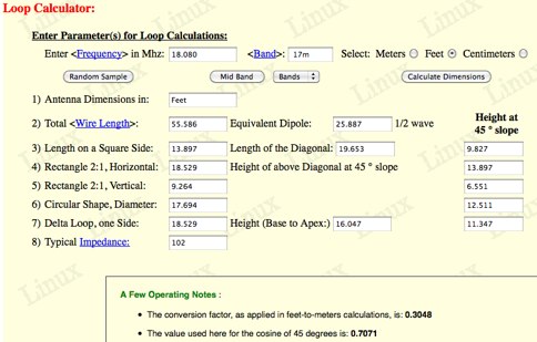 KA1FSB loop calculator give you a quick overview of the feasibility of "squeezing" a loop into your available yard or apartment space. The easy calculator yields a reasonable approximation of dimensions, to within 5% over the amateur bands, using typical wire gauges ranging from 12-18 AWG.
 -
 Dipole antennas, unique broadband antennas, trap dipole antennas, coils, accessories for HF radio
 -
 Examines the operational differences between **quad** and **Yagi** antenna designs, focusing on their respective performance characteristics for amateur radio applications. The document highlights key metrics such as forward gain, front-to-back ratio, and bandwidth, which are crucial for effective DXing and contesting. It discusses how element configuration, boom length, and material choices impact the efficiency and radiation patterns of each antenna type across various HF bands. Practical considerations for antenna builders are addressed, including structural integrity, wind loading, and overall weight, particularly when using fiberglass spreaders for quads. The resource also covers precipitation static reduction in quads due to their closed-loop design and their ability to operate efficiently at lower elevations compared to Yagis. It provides insights into dual-polarization feed systems for quads, offering independent vertical and horizontal feed points for enhanced operational flexibility.
 -
 PKW Antennas for ham radio bands, Quads, delta loops, log periodics antennas for military and professional use by Ditta Martelli fabbrica italiana antenne
 -
 a simple, low-cost, trapless short vertical antenna which amazingly works on three HF bands (20, 15 and 10 meters)
 -
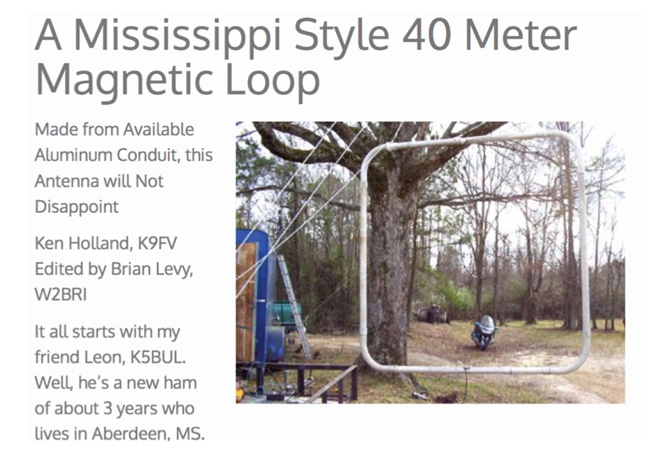 A Mississippi Style 40 meter magnetic loop made from available aluminum conduit, this antenna will not disappoint by Ken Holland, K9FV
 -
 Demonstrates the construction of a **remote antenna tuner** utilizing a standard radio-controlled (RC) servo mechanism to adjust a variable capacitor. The design focuses on enabling remote tuning for narrow-bandwidth antennas, specifically mentioning frame and packing crate antennas, from within the shack. It covers the mechanical arrangement for integrating the servo with a capacitor and provides a circuit diagram for a control unit that generates the necessary 0.5mS to 1.5mS pulse-width modulation (PWM) signals to drive the servo's 180-degree rotation. This setup was successfully tested with up to 20 watts RF power without arcing or adverse effects on the servo, though tuning was performed at 1 watt for VSWR readings. The resource highlights the use of inexpensive, readily available components, such as Futaba servos, and details critical considerations like power supply decoupling with a 47uF capacitor to prevent unintended servo movement upon power-off. The system provides a practical solution for optimizing antenna performance for specific frequencies without manual adjustment at the antenna itself.
 -
 A wire yagi antenna for 20 and 40 meters band suitable for outdoor and field day operations
 -
 M1IOS Wonder Whip antenna - The M1IOS Wonder Whip A 10 dollars QRP Portable Multiband Antenna for HF, VHF and UHF A variation on the Miracle Whip and Wander Wand. This antenna tuning unit will get your SWR really low on telescopic whips, mobile 3/8th antenna and long wires. A remarkable little tuner that really works!
 -
 Presents the KE4UYP linear-loaded vertical antenna design, which introduces very little loss on 80 or 160 meters, achieving an overall radiation efficiency of 80% to 85%. This design addresses common pitfalls of traditional base-fed verticals by placing the majority of the current at the top of the antenna, eliminating the heavy reliance on extensive ground radial systems. The author's initial 10-meter model, only three feet tall, yielded 5/9 signal reports to Anchorage, AK, and Europe, confirming its effectiveness. The antenna incorporates both vertically and horizontally polarized radiators, with a 1/4 wavelength horizontal counterpoise located at the feed-point, near the top, to create an almost totally omnidirectional pattern with high wave angle horizontally polarized radiation. This dual polarization ensures even illumination across all take-off angles, making it effective for both local contacts and **DXing**. The vertical element is linear loaded, adding capacitance reactance and making it longer than the horizontal element to achieve resonance and raise the feed-point impedance to 50 ohms. Fine-tuning the antenna requires careful adjustment, as tower reactance can vary. The article suggests starting with 80 feet for 80m and 170 feet for 160m for the vertical wire, then trimming for resonance. Bandwidth specifications include 300 kHz under 2:1 **SWR** on 80m and 100 kHz on 160m when suspended between trees, or 150 kHz on 80m when side-mounted on a tower.
 -
 Multi Band Quad,Cushcraft R5, R7, R7000, repair and maintenance, Remote Antenna Switching, Hexagonal Beam, Automatic Band Decoder, Low Band Verticals, Crank-up Tiltover Tower etc
 -
 The Flower Pot Antenna project details a portable dual-band antenna primarily operating on 10 meters, with secondary resonance near the 30-meter band. Construction involves winding RG58 coaxial cable uniformly around a large plastic flower pot, approximately 70cm high with a 60cm top diameter. The design eliminates the need for radials, contributing to its compact and lightweight nature. Key construction steps include soldering the inner conductor to the shield at one end of the wound cable and connecting the wound cable's shield to the rig cable's inner conductor at the base. An LC network, comprising a variable capacitor (0-200pF) and an inductor (10 coils, 5cm diameter, 2mm wire), is inserted between the wound cable's inner conductor and the rig cable's shield. Tuning is performed with an antenna analyzer, adjusting cable length and the variable capacitor for optimal impedance on 10 meters. The antenna performs effectively when installed horizontally.
 -
 A 3 band dipole for 10 15 and 20 meters band, easy to build, and that can be easily setup in any occasion, inclunding field days or portable operations
 -
-
 Short dipole antenna for 40 meter ham band. Can be put up in the space required for a 20 meter dipole.
 -
 Build the PAC-12 Antenna a multi-band portable vertical designed by KA5DVS, here's an award-winning, easy-to-homebrew, multi-band portable vertical antenna designed by long-time antenna aficionado James Bennett, KA5DVS. He's documented the design and construction plans for a portable antenna
 -
 HF multiband mini delta compact and easy assembling antenna that cover from 20 to 10 meters by GM3VLB
 -
 A dual-bander for 80M and 40m. An Extended Double Zepp (EDZ) is a 5/4 wavelength center-fed dipole. This article will introduce the Half-Extended Double Zepp (HEDZ) which has characteristics that a lot of amateur radio operators should find quite interesting
 -
 Article with detailed pictures of an endfeed antennna for 20 and 30 meter band
 -
 Constructing and designing full size, single band stacked yagi antenna arrays
 -
-
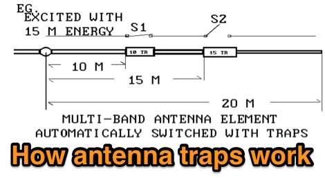 An interesting article about homebrewing antenna traps for multiband antennas by VE3GK
 -
 The multi-band trapped dipole is resonant on approx 3.7, 7, 14, 24 7 28.5 Mhz. The overall top length needs to be approximately 32.9 Meters
 -
 Even if using a tuner this multiband antenna will let you operate from 160 to 10 meters. If you could only put up one antenna, this would be it. Project by N0KHQ.
 -
 This antenna is intended as a simple, inexpensive solution for the newcomer to experiment across the 40m band (7.0-7.2MHz) when only restricted space is available
 -
 This page describes the design and construction materials W8WWV used to build a coaxial cable trap. A coaxial cable trap is a parallel resonant circuit that is usually inserted in an antenna element to enable multiband operation.
 -
 Modified version of the Telerana antenna which was orginially featured in the July 1979 issue of QST. The array is suspended within a framework made of fiberglass poles emanating from a central hub with the ends tied together with light weight rope around the perimeter. 10-15-20-30-40 meter band coverage
 -
 The resource provides detailed information about a five-band indoor magnetic loop antenna designed for amateur radio operators. This antenna is capable of operating on the 20, 17, 15, 12, and 10 meter bands, making it a versatile choice for various HF communications. Constructed from a single 3-meter length of 22 mm copper tube, the design emphasizes compactness and efficiency, which is particularly beneficial for operators with limited space. The page includes insights into the construction process, tuning, and operational tips, catering to both novice and experienced users. In addition to the technical specifications, the resource also discusses the advantages of using a magnetic loop antenna indoors, such as reduced interference and improved performance in urban environments. It serves as a practical guide for those interested in building their own antenna, offering a straightforward approach to antenna design and construction. Overall, this resource is a valuable addition to the toolkit of amateur radio enthusiasts looking to enhance their station with an effective indoor antenna solution.
 -
 Over 30 distinct shortwave (SW) receiver models are reviewed, offering insights into their performance, features, and user experiences. These evaluations, contributed by readers of the Usenet newsgroup **Rec.radio.shortwave**, cover a wide array of portable and tabletop radios, including popular units like the Grundig YB-400, Sony ICF-SW77, and various Realistic DX series models. Each review details aspects such as frequency range, tuning steps, SSB functionality, antenna performance, and construction quality, often comparing them to other receivers or ham transceivers like the Icom 725. For instance, the Grundig YB-400 review highlights its 144-30000 kHz AM/SSB coverage, direct keypad entry, and 40 station memories, noting its useful narrow bandwidth and tone switch for adjacent signal separation. It also discusses the **SSB mode** stability and the limitations of its 1 kHz frequency resolution for precise zero-beating. The review further details antenna performance, including the effectiveness of the built-in whip, the provided 7m reel antenna, and the potential for overload with larger outdoor antennas. Other reviews delve into specific issues, such as the Sony ICF-SW77's frequency display inaccuracies and timer malfunctions, or the Realistic DX-342's compact size and surprisingly good MW DXing capabilities despite its analog tuning. The collection provides practical, user-generated feedback on sensitivity, selectivity, audio quality, and ergonomic features, helping shortwave listeners understand the real-world performance and quirks of these receivers.
 -
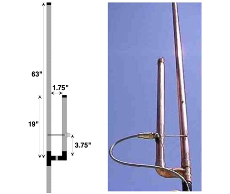
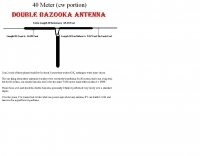 A double bazooka antenna plan for the cw portion of the 40 meter band
 -
 Demonstrates the construction and on-air performance of the _NB6Zep_ antenna, a modified 20-meter Extended Double Zepp design optimized for multi-band operation from 40 through 10 meters. The resource covers basic design principles, including dimensions of 66 feet horizontal and 5 feet vertical elements, and specifies open ladder line or TV twin lead for the transmission line. It details material selection for low-cost wire antenna construction, such as 18 AWG wire for the legs and ceramic or plastic insulators, along with practical tips for soldering connections and insulating against moisture. The author, NB6Z, shares insights from extensive _EZNEC_ modeling to optimize the antenna's total length for a 40-meter half-wave dipole footprint and feed line length for direct tuner connection. The article presents field results, including successful _PSK31_ contacts from Oregon to the East Coast on 40 and 30 meters with 50 watts, even at a low height of 6 feet. It provides detailed performance characteristics for each band, noting the _NB6Zep_'s highest gain (over 3 dB) and sharp, medium-angle lobes on 20 meters, which yielded strong DX reports to locations like Korea, Japan, and Argentina. For 17 and 15 meters, it describes a butterfly-like pattern with broad lobes, while 12 and 10 meters exhibit narrow, directional lobes in an "X" configuration. The author also shares personal experiences operating successfully for over a decade in an antenna-restricted environment using the NB6Zep and other stealth wire antennas.
 -
 An easy to build Hexbeam antenna built with bamboo sticks for the six meters band
 -
 The page provides detailed information about the construction of a full-size 160M 3 element beam antenna and an 80M 5 element beam antenna on a 330ft tower. It includes specifics about the tower height, types of antennas, elements, gain, take off angles, front-to-back ratio, operating frequencies, weight, and dimensions of the beams. The content is aimed at amateur radio operators interested in building high-performance antennas for the 160M and 80M bands. This Antenna is now been destroyed and is no more operational.
 -
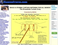
 The Bruce array is a simple, often-forgotten wire antenna array that is advantageous for 80 and 160 meters, where typical gain antennas are very large. This bi-directional broadside vertical array is only 1\4 lambda high and does not require a ground system. It offers substantially greater SWR bandwidth than the half-square or bobtail curtain. A 4-element Bruce array used by N6LF showed a gain of about 4.6 dB compared to a 1\4 lambda vertical with 8 elevated radials, with a 2:1 SWR bandwidth greater than 400 kHz. The antenna is simple and its dimensions are flexible.
 -
 Delta Loop Antenna for 15m band. This antenna is made for operating from outdoors, mainly from mobile shack. Drive to a parking you like, then build it up. Just half an hour later, you can enjoy slightly better gain than normal dipole.
 -
 Presents a catalog of **QRP** transceivers, antenna tuners, and related accessories for amateur radio operators. The product line includes the ZM-2 antenna tuner, designed for efficient impedance matching across HF bands, and the NW-series QRP transceivers, offering low-power CW operation. Additionally, the site details various ladder line insulators and specialized connectors, emphasizing robust construction for field deployment and home station use. Each product listing provides specifications, operational parameters, and pricing information. Compares the features of different **QRP transceiver** models, such as the NW-40 and NW-20, highlighting their respective band coverage and power output capabilities. The ZM-2 tuner's performance is detailed with typical SWR reduction figures for various antenna types, demonstrating its utility for portable and fixed stations. Customer testimonials and product images illustrate the practical application and build quality of EMTECH's offerings, providing insights into their durability and ease of integration into existing amateur radio setups.
 -
 The cobweb antenna it is basically a 5 band antenna comprising of 5 full half wave dipoles for each band - between 10 meters and 20 meters, the antenna is also resonant on 6M and can be modeled even for VHF frequencies.
 -
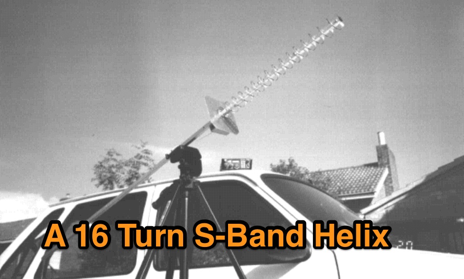 This design represents the smallest practical antenna for Oscar-13 mode-S. Perfect beacon reception at all times is possible, and acceptable SSB even at 43,000 km range.
 -
 A simple dual band VHF UHF jpole antenna Projects by Dale Kubichek