Search results
Query: c band antenna
Links: 1419 | Categories: 68
Categories
- Antennas > 20M > 20 meter Dipole Antennas
- Antennas > 20M > 20 meter Vertical Antennas
- Antennas > 20M > 20 meter Yagi antennas
- Antennas > 40M > 40 meter Dipole Antennas
- Antennas > 40M > 40 meter Loop Antennas
- Antennas > 40M > 40 meter Yagi Antennas
- Antennas > 6M > 6 meter J-Pole Antenna
- Antennas > 6M > 6 meter Moxon Antennas
- Manufacturers > Antennas > VHF UHF Microwave > Discone Antennas
- Radio Equipment > HF Vertical Antenna
- Manufacturers > Antennas > VHF UHF Microwave > HT Antennas
- Manufacturers > Antennas > VHF UHF Microwave > Mobile Antennas
- Manufacturers > Antennas > VHF UHF Microwave > Quad Antennas
- Manufacturers > Antennas > HF > Quad Antennas
- Manufacturers > Antennas > VHF UHF Microwave > Satellite antennas
- Manufacturers > Antennas > HF > Mobile Antennas > Screwdriver Antennas
- Operating Modes > Top Band
- Manufacturers > Antennas > VHF UHF Microwave > Vertical Antennas
- Radio Equipment > HF Portable Antenna
- Antennas > 10M
- Antennas > 17M
- Antennas > 20M
- Antennas > 23cm
- Antennas > 2M
- Antennas > 30M
- Antennas > 4M
- Antennas > 60M
- Antennas > 80M
- Radio Equipment > HF Vertical Antenna > Butternut HF2V
- Antennas > CobWebb
-
 A 30 cm antenna for the six meters band in japanese
 -
 Experimental Long Boom Antennas - CP, LPDA, multiband with several NEC Files for 50MHz 144MHz 222 MHz 432MHz but also 902MHz and 1296 MHz Antenna projects. Includes also for each antenna model, in a general comparison table each antenna characteristics including Directive Gain, G/T, E-F/R, H-F/R abd Boom Length. This is a great value comparison table of several commercial and home made VHF UHF antenna projects.
 -
 TelExpress provides a wide array of RF and data connectivity products, including various coaxial cables like LMR-series equivalents, fiber optic cables, and Ethernet solutions. Their inventory supports diverse amateur radio and telecommunications requirements, from antenna feedlines to network infrastructure. The site emphasizes bulk cable availability and custom assembly services, catering to both individual hams and larger installations. Key offerings include _low-loss coax_ for HF and VHF/UHF applications, along with a comprehensive selection of RF connectors. They also supply patch panels, Ethernet cables (Cat5e/Cat6), and general wireless and telecom hardware. Customers can find components for building robust station infrastructure, ensuring signal integrity across various frequency bands. The platform facilitates procurement of essential parts for new builds or upgrades, supporting reliable RF system performance.
 -
 A j-pole antenna plan with drawings and dimensions that can help you on building your own j-pole antenna for the six meters band
 -
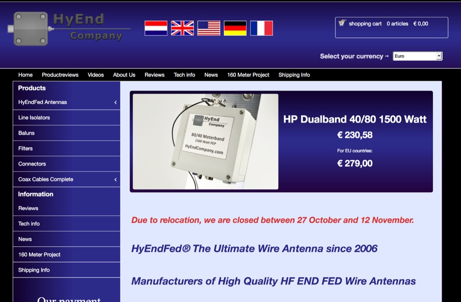 HyEnd is a dutch amateur radio antenna manufacturer. Makers of the popular HyEndFeed Antennas, produce Baluns, bandpass filters and selle Line isolators, coax cables and connectors.
 -
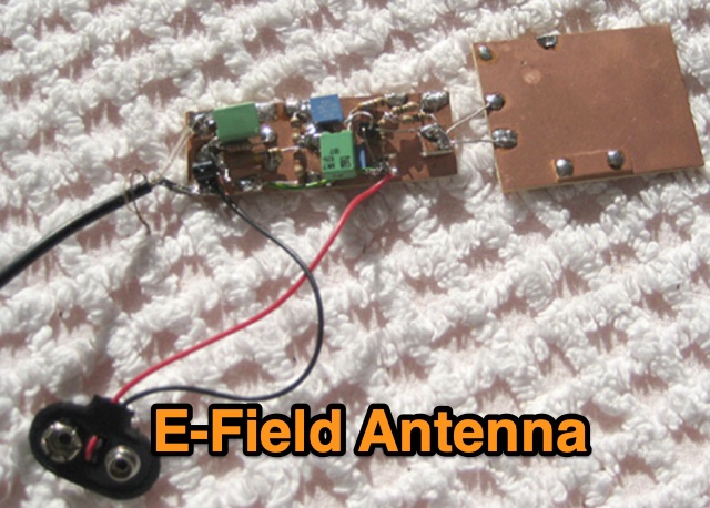 A small active voltage probe antenna to aid reception on the LF bands
 -
 An article about the Beverage antennas, super long wire receiving antennas thar are unidirectional and have a very low noise that makes this antenna excellent for low band dxing. By Thomas R. Sundstrom W2XQ, 73, June 1981, 73 Magazine
 -
 A very essential j-pole antenna for 144 MHz. To adjust the SWR you will have to play with the 40mm distance between the coax feed and the braid inner conductor connection
 -
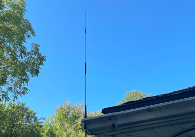
 This article describes a simple yet effective multi-band vertical HF antenna design that performs exceptionally well across 80m to 10m bands. The antenna consists of a 13.4m wire mounted on a 12.4m Spiderpole, complemented by four 12m radials and a ground rod. Initially tuned with a manual LC circuit, it was later upgraded with a CG3000 remote auto ATU for convenient band switching. Despite antenna modeling software suggesting limited performance on higher frequencies, the system demonstrated excellent DX capabilities across all bands, outperforming more complex vertical antenna designs.
 -
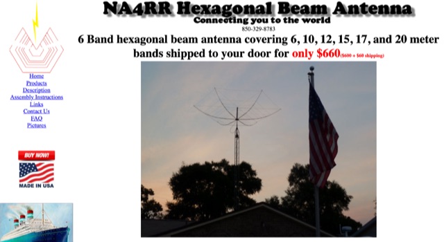 NA4RR manufacture a six band hexagonal beam antenna for ham radio, covering 6, 10, 12, 15, 17, and 20 meter.
 -
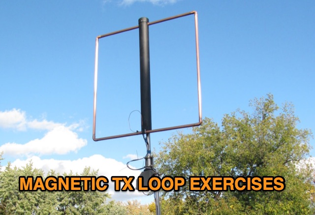 Explore two magnetic loop antenna constructions, utilizing a 6-foot and a 12-foot square loop. Accompanied by a detailed description, the 6-foot loop features a built-in stepper motor control circuit, while the 12-foot loop incorporates a separate loop controller. Efficiency, tuning ranges, and the innovative autotuning solution using a microcontroller are discussed, offering insights into overcoming the antenna's narrowband limitations.
 -
 HF Antennas is a division of Comsystems Solutions we manufacture wire broadband antennas and different type.
 -
 This article shares the author's experience with building antennas. After putting a large magnetic loop project on hold, they decided to try a base-loaded vertical antenna. The author explains how they chose to design a new antenna from scratch, aiming for a frequency of 7 MHz. They describe the calculations needed to find the right coil inductance and how they used 3D-printed parts for the construction. The article wraps up with results from their initial tests, showing good communication on different bands and highlighting the success of their design.
 -
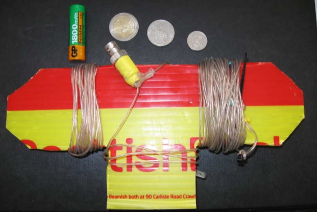
 Experimentin wire antennas on top band using several type of aerials. This includes a 40 to 160 meters EndFed Half Wave kite antennas and 160m/80m loaded vertical antenna.
 -
 Extended Double Zepp measurements for all ham bands, and online calculator. The antenna is constructed much like an ordinary Dipole antenna but with 5/8 Wavelength Elements matched with an added Impedance Matching Section of balanced feed line
 -
 Operating marine mobile with antennas for 15-17-20 meters band.
 -
 The original HEXBEAM was developed by Mike Traffic, N1HXA, in the early nineties. It is true that an M over W configured yagi antenna that resembled a butterfly was earlier tried successfully. But the advanced electrical design, the characteristic nesting concept and central terminal post that enable the multi band functionality along with the basic hardware design were all developed by Mike Traffie.
 -
 Operating an amateur radio station effectively requires reliable coaxial cable to minimize signal loss between the transceiver and antenna. SIVA Cavi, an Italian manufacturer, produces a range of coaxial cables, including specific 50 Ohm low-loss types suitable for amateur radio applications. Their product line features cables like **RG 58 SHF1**, **RG 213 SHF1**, and **RF 400 SHF1**, which are commonly deployed in HF and VHF/UHF setups. The company also offers specialized cables such as the **HF 214 UF Ultraflex**, a high-performance broadband low-loss 50 Ohm cable designed for flexibility and reduced attenuation across various amateur bands. These cables are engineered with solid or foam dielectric materials, impacting their electrical characteristics and suitability for different power levels and frequency ranges. For instance, foam dielectric cables often exhibit lower loss at higher frequencies, a critical factor for VHF/UHF operations. Beyond amateur radio, SIVA Cavi manufactures cables for digital video broadcast, offshore marine use, and fire detecting systems, demonstrating a broad engineering capability in coaxial cable technology.
 -
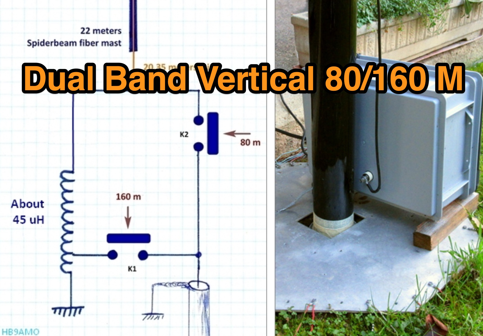 This page provides detailed information on various antenna designs specifically tailored for hams operating on the 80m and 160m bands. The article covers the pourpose and usefulness of each design, helping hams optimize their radio communication capabilities on these popular bands. Whether you are a beginner looking to improve your setup or an experienced operator seeking new ideas, this page offers valuable insights to enhance your ham radio experience on the 80m and 160m frequencies.
 -
 A dual band 40-80 vertical antenna on an 18m Spiderbeam Fiberglass Spiderpole, with monoband performance
 -
 This article explores the evolution of antenna choices for DXpeditions, focusing on the shift from mono-band VDAs to a multi-band solution. It details the design and construction of a lightweight, versatile 20-17-15m VDA, utilizing readily available materials like fishing rods and IKEA breadboards. The author discusses challenges, adjustments, and offers guidance for replication.
 -
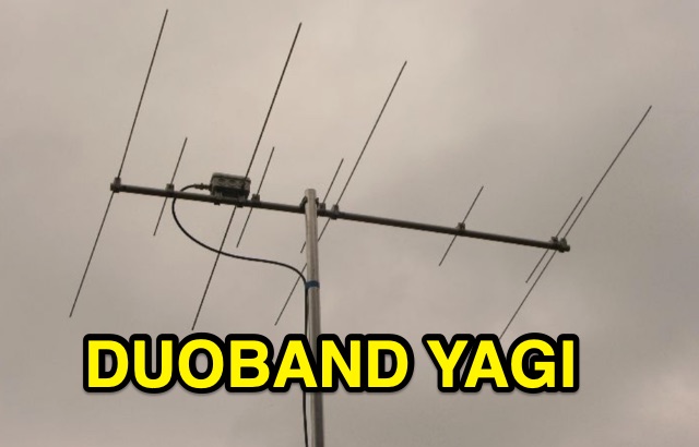 Duoband Yagi 2m/70cm with 4 Elements on 2 m and 5 Elements on 70 cm and one Feed point. The 4-El.-Ultralight-Yagi for 2m can be used on 70cm with an SWR of 1,5 without any changes.
 -
 Explains the fundamental purpose of a repeater, detailing how these automated relay stations overcome distance and terrain limitations for VHF/UHF communications. It traces the historical development from early Bell Telephone Labs "relay" stations in 1922 to Art Gentry, W6MEP's, pioneering K6MYK amateur radio repeater in the mid-1950s, which remains active today. The resource clarifies the distinction between simplex and duplex operation, including the unique function of a "parrot repeater" for single-frequency recording and playback. Delving into the internal workings, the guide breaks down a repeater into its core components: the antenna system, feedline (often _Heliax_ or hardline for minimal loss), duplexer, receiver, transmitter, and controller. It emphasizes the critical role of the duplexer in preventing receiver desensitization by isolating transmit and receive signals, even with distinct frequencies. The discussion highlights the importance of high-performance, durable antennas and low-loss feedlines, citing examples of equipment installed in the 1960s and 1970s that are still in perfect working order. Operating a repeater is also covered, with an explanation of frequency offset (e.g., the 600 kHz standard for 2 meters) and the function of _CTCSS_ (PL tone) for access. It outlines standard input/output offsets for various bands, from 6 meters to 23 centimeters, while noting regional variations. The guide also touches on features like autopatch and Digital Voice Recorders (DVRs), providing a solid foundation for understanding repeater technology and usage.
 -
 A homebrew 13 elements yagi antenna for two meters band. These project includes two model of the same antenna with a 6 and 7 meter boom length. Detailed pictures and nec files are available for download
 -
 1260 MHz yagi antenna for ATV with a total Bandwidth (3 dB) 1240-1280 MHz and 10 dBd gain
 -
 A dual band X-frame wire antenna made using 4 turns for response down to 3 MHz or so, and 2 turns (switched) for response up to around 18 MHz. The loop configurations are tuned using common eBay 365 pF tuning caps.
 -
 In the quest for an ideal field portable antenna, the author recounts experiments involving various wire configurations. While a previous candidate, a 41ft random wire, proved effective but lacked stealth, the search led to a surprising rediscovery of a design previously rejected—the Rybakov Antenna. With a focus on simplicity, rapid deployment, and multiband capability, the author explores the versatility of a 26ft Rybakov, avoiding the halfwave trap. The article delves into the antenna's performance and its potential as a discreet, resonant solution for field operations, addressing the challenges encountered during a POTA activation. Additionally, the Unun/Balun design used in conjunction with the Rybakov Antenna is discussed, providing insights into achieving a balanced system.
 -
 The author reflects on expanding their antenna for 80m coverage during lockdown. They extend the End Fed Half Wave (EFHW) using a Spiderbeam pole and "cheating" by dog-legging across their garden. Despite challenges, they achieve coverage for multiple bands with minimal cost. Practical Wireless features EFHW antennas, including a pre-made 20m EFHW extended for 40m.
 -
 Building an End-Fed Half-Wave (EFHW) antenna from a kit, as detailed by Frank Bontenbal, PA2DKW, with process photos by Bob Inderbitzen, NQ1R, offers a practical approach for hams. This specific kit, a collaboration between ARRL and HF Kits, targets 10, 15, 20, and 40 meters, making it a versatile option for HF operations. Unlike a center-fed dipole, the EFHW is a half-wavelength antenna fed at one end, which simplifies deployment, particularly for portable use. The construction guide meticulously outlines the assembly of the 49:1 impedance matching network, crucial for transforming the antenna's high impedance (around 2,500 Ohms) to a transceiver-friendly 50 Ohms. Steps include preparing the enclosure by drilling holes for the coaxial connector and antenna connections, followed by the precise winding of enameled copper wire onto a toroid to create the transformer. The guide emphasizes careful insulation removal and soldering for reliable connections. Final assembly involves integrating a 100 pF capacitor for higher band compensation, soldering the transformer's primary and secondary sides, and conducting SWR tests with a 2K7 resistor or a half-wavelength wire. The document also provides examples of wire lengths for different bands, such as 16 feet for 10 meters or 66 feet for 40 meters, demonstrating the transformer's adaptability for various half-wavelength configurations.
 -
 The _G3TSO_ Mobile Antenna Page details construction and tuning methods for mobile antennas operating across **10 to 160 metres**. The content describes a Hustler-based design, optimized for RF performance and vehicle speeds, featuring centre loading. For optimal operation on various bands, the loading coil placement requires clearance from the vehicle body. Antenna resonance is critical for efficient mobile operation. A mobile antenna's base impedance may be as low as 27 ohms, requiring specific matching to achieve maximum radiation, as a minimum SWR at the transmitter does not always indicate resonance or maximum output. Tuning involves physical adjustment of antenna length to achieve resonance at the operating frequency. The _G3TSO_ page outlines a tuning procedure utilizing a low-power signal source and a field strength meter to identify maximum radiation before impedance matching. Loading coil placement, either at the base, center, or top of the antenna, influences radiation efficiency and mechanical stability for mobile installations. Centre-loaded whips, such as the Hustler design, offer a compromise between efficiency and stability, often for single-band operation. Helically wound antennas, including those for **28 MHz**, may present base impedances around 17 ohms, resulting in a 3:1 SWR at resonance. Low resistance grounding at the antenna base is also specified for optimizing performance and minimizing RFI during mobile operation. DXZone Focus: Mobile | Any | Antenna Tuning | HF
 -
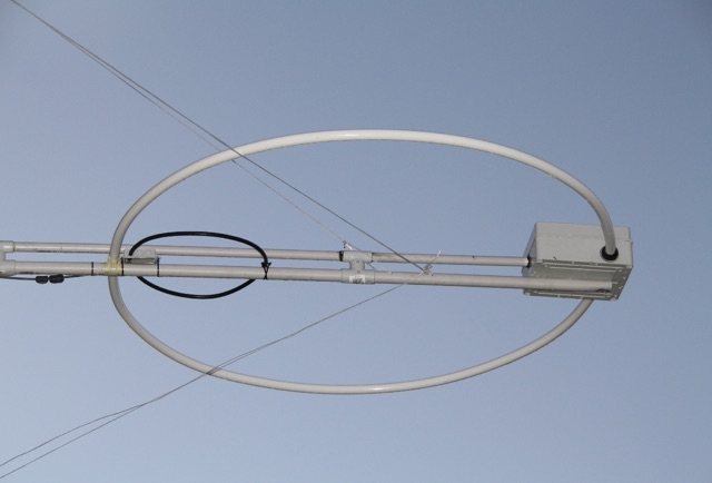 Pictures of a magnetic loop antenna for hf bands that works from 10 MHz to 24 MHz
 -
 Operating within the low-frequency spectrum, transformers serve critical roles in antenna systems, particularly for 160m applications. The resource details the construction and performance of 1:1 transformers built on BN-73-202 cores, emphasizing their use as hybrid combiners or phase inverters for RX antenna arrays. Measurements reveal that these transformers exhibit minimal losses, around 0.12 dB at 1.8 MHz, with variations based on wire type and number of turns. The analysis includes comparative data on transformer performance, highlighting the impact of different winding techniques on frequency response. Notably, the use of coaxial cable for winding improves bandwidth while maintaining low-frequency efficiency. The resource also discusses braid breaker transformers, which minimize inter-winding capacitance, achieving low losses around 0.21 dB at 1.8 MHz. These insights are crucial for optimizing low-band antenna systems, allowing operators to make informed decisions regarding transformer design and implementation.
 -
 Dipole for 40m band. It is a simple linear loaded dipole feeded with 450-Ohm openwire feedline. Designed it for resonance at 7.050 MHz, can be tuned on 30m and 80m bands with an external antenna tuner. Build with simple electrical copper wire (2.5 mmq/13 awg) and two fishing poles with size of about 7 m/23 ft.
 -
 A portable loop antenna, made with a 3 meter loop resonates with the chosen capacitor from just below 7MHz to about 28.300MHz which makes it usable on the bands from 40m to 10m.
 -
 The antenna I built was inspired by a portable delta loop designed by Doug DeMaw, W1FB. Given that I constrained myself to a 50-foot roll of speak wire, I scaled my antenna for the 20M band. Using the formula, 1005 divided by the frequency in megahertz, I calculated a total length of 71 feet (21.6 meters) for the center of the 20M band.
 -
 Constructed in May 2008, this innovative 4m tall electrically full-size halfwave vertical dipole, tunable to multiple bands, offers HF coverage despite its space-saving design. Inspired by cost-effective DIY alternatives, the antenna design departs from conventional center-fed approaches, utilizing asymmetrical dimensions. Despite resonance challenges, the antenna's performance remains viable, boasting broad bandwidth and adaptability, as demonstrated through SWR measurements and EZNEC predictions.
 -
 This multiband transverter project features power output at 13,8V 50MHz 15W, 70MHz 10W, second harmonic < 65dBc. Single N connector of antenna, suitable for a dual band Yagi. Article include Block Diagram for Dual Transverter and low pass filters
 -
 A concept to use common, low-cost parts to mount a VHF/UHF dual-band antenna to help people who have HOA restrictions, are renters, or desire low-visibility characteristics get on the air.
 -
 Originally designed by John Kraus, W8JK in about 1940, this antenna has some interesting properties. The W8JK antenna is 2 (Two) centre-fed double-dipole fed by a pair of anti-phase signals. Small size, simple antenna, offer nice performance but need a tuner. Tested in this project from 30m to 6m bands
 -
 A coaxial cable trap is a fundamental component in multiband antenna design, enabling a single radiator to resonate efficiently on multiple frequencies by electrically shortening or lengthening the antenna element. This project focuses on constructing such a trap for a vertical antenna operating on the 10 MHz (30m) and 14 MHz (20m) amateur bands, providing practical insights into its fabrication and integration. The article outlines the specific dimensions and winding techniques for the coaxial trap, emphasizing the use of readily available materials. It details the physical construction of the vertical element, including the mast and radiating sections, to achieve optimal performance across both target bands. The author shares personal experiences with similar trap designs, noting their effectiveness in previous horizontal dipole configurations. Key construction steps are illustrated with _original photos_, showing the assembly of the trap and its incorporation into the overall antenna structure. The design aims for a compact footprint, making it suitable for limited space installations while still delivering effective DX capabilities on the **30-meter** and **20-meter** bands.
 -
 In this article, Steve G0UIH presents a straightforward guide for constructing a lightweight 15m 3 Element Yagi antenna with impressive performance metrics. With a focus on ease of construction and efficiency, the design boasts a nearly 8.2dbi forward gain and 30db front to back ratio. Utilizing readily available materials and a hairpin match for impedance matching, this Yagi offers broad bandwidth and simple tuning for optimal operation across the 15m band.
 -
 Learn how to easily build a 10-meter vertical antenna, perfect for DX contacts on the amateur radio bands. This flowerpot or T2LT design is portable, efficient, and ideal for ham radio operators looking to improve their DX performance. With just a few basic tools and materials, you can construct this antenna for portable operations or as a home station setup. Discover how to set up the antenna, improve its performance by raising it higher, and start making contacts with stations around the world. Watch a step-by-step guide on YouTube for building and testing this DIY ham radio antenna.
 -
 This antenna works on 17, 20, and 30 meters, with the best bandwidth on 20 meters. The bandwidth on 17 and 30 is quite small but usable. There is a 20 KHz bandwidth on 20 meters.
 -
 Integrating a **160-meter vertical wire antenna** with an existing 80-meter Yagi system presents unique challenges for Top Band operation. This project outlines the author's experiences with seasonal antenna removal and reinstallation, a necessary task for agricultural land use. It details specific issues encountered, such as incorrect coil sizing and relay configuration problems, providing practical insights into common pitfalls. The article describes the iterative tuning process, comparing **NEC model** predictions with actual on-air performance. It emphasizes the importance of precise measurements and adjustments to achieve optimal resonance and impedance matching. The author shares lessons learned from troubleshooting, including the impact of ground system integrity and feedline considerations. Concluding with an antenna checkup, the resource addresses long-term maintenance aspects, including galvanic corrosion prevention and general upkeep for reliable operation.
 -
 This article describes the construction of a three-band vertical antenna for the WARC bands (10, 18, and 24.9 MHz). Unlike a previous design using thin wire requiring a complex matching device, this version uses a telescopic set of pipes, reducing reactances and simplifying the matching device to two coils and two capacitors. The article provides details on the antenna model, the matching device circuit, and tuning methods, including the use of frameless coils and variable capacitors. With proper tuning, the antenna achieves a VSWR not exceeding 1.3 across all bands, demonstrating a practical and efficient design for amateur radio enthusiasts.
 -
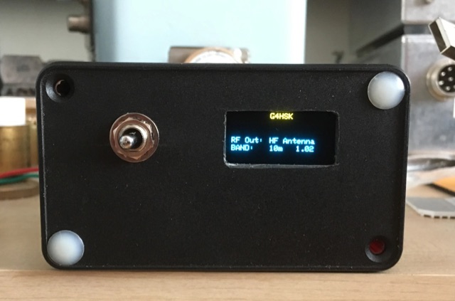 An Arduino Based Antenna Switch For The IC-7300 that monitors the band voltage from the rear accessory socket on the IC-7300. Two RF antenna relays are used to switch to the appropriate output.
 -
 The reason for making this antenna was the desire for a vertical (hence DX-ish) antenna that would cover at least 20m that would fit on my 5m fishing pole. This antenna can work on 20m 17m 15m bands and it is suitable for SOTA operations
 -
 The HB9CV antenna calculator aids amateur radio enthusiasts in designing antennas for VHF and UHF bands. By inputting the working frequency, users can obtain crucial dimensions like dipole lengths and distances. The tool, based on the HFSS antenna model, provides data on impedance, VSWR, and gain, optimizing front/back radiation ratios. It includes tips for fine-tuning using a Г-matching balun and compensating capacitor, ensuring effective performance and minimal VSWR for enhanced radio communications and direction finding.
 -
 Build A Shortened 40 Meter Vertical antenna For POTA / SOTA Activations. A project for a portable wire antenna for 40 meters band suitable for POTA or SOTA operations.
 -
 A medium power End Fed Half Wave Antenna coupler, specifically tuned to the QRP frequency of 7030 kHz. Constructed from coil stock and capacitors, it achieves an impedance ratio of 64:1. The coupler has proven effective for power ranges from 2 to 100 Watts on the 40m band.