Search results
Query: band
Links: 716 | Categories: 111
This query is too generic. Please try adding an additional term to focus your research.
Categories
- Ham Radio > Band Plans
- Antennas > Multiband
- Operating Modes > Top Band
- DX Resources > Beacons > 10 GHz Beacons
- DX Resources > Beacons > 10 meter beacons
- Antennas > 10M
- Antennas > 17M
- Antennas > 20M > 20 meter Dipole Antennas
- Antennas > 20M > 20 meter Vertical Antennas
- Antennas > 20M > 20 meter Yagi antennas
- Antennas > 20M
- Antennas > 23cm
- Antennas > 2M
- Antennas > 30M
- Antennas > 40M > 40 meter Dipole Antennas
- Antennas > 40M > 40 meter Loop Antennas
- Antennas > 40M > 40 meter Yagi Antennas
- Antennas > 4M
- Antennas > 6M > 6 meter J-Pole Antenna
- Antennas > 6M > 6 meter Moxon Antennas
- Antennas > 60M
- Operating Modes > 70 MHz
- Antennas > 80M
- Radio Scanning > Aeronautical
- Operating Modes > Aircraft scatter
- Radio Equipment > VHF-UHF Handhelds > Baofeng UV-3R
- Technical Reference > Beacon keyers
- Software > Beacon Monitoring
- DX Resources > Beacons
- Technical Reference > Radio Frequency Interference > BPL
-
 Band Master is a program for Radio Amateurs that downloads DX spots and displays them in different ways, including a graphical band map. It can be used either as a stand alone application or as part of a logging or contesting software. Price USD 25
 -
 An homebrew project for a 3 elements yagi monoband antenna for the 20 meters by 9M2MSO
 -
 This technical note explores the application of **Moxon rectangle** antennas for WARC bands, specifically 17 and 12 meters, as compact directional alternatives to standard Yagis. It details three design approaches: a dual-band Moxon using open-sleeve coupling, a Moxon-Yagi combination, and a simplified 1.5 Moxon rectangle. The document provides specific dimensions in feet for aluminum tubing elements (0.75" and 0.5" diameter) for each configuration, along with projected free-space gain, front-to-back ratio, and feedpoint impedance (R+/-jX Ohms) across the respective band segments. Performance tables illustrate gain (dBi), front-to-back ratio (dB), and 50-Ohm VSWR for each design. The dual-band Moxon, despite its compact 7-foot boom, is not recommended due to extreme sensitivity to construction variations, leading to rapidly changing performance characteristics. The Moxon-Yagi combination, featuring a 17-meter Moxon and a 12-meter director-driver Yagi, is presented as a more practical and adjustable solution, offering stable performance with a 10-foot boom. NEC model descriptions are included for simulation in programs like EZNEC, NEC-Win Plus, AO, or NEC4WIN.
 -
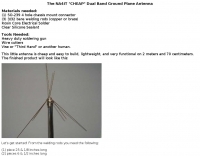 This little antenna is cheap and easy to build, lightweight, and very functional on 2 meters and 70 centimeters by NA4IT
 -
-
 If you are looking for an easy antenna for your favorite band, you can't go wrong with an halfwavelenght dipole, all you need is 3 insulators and some wire
 -

-
 Why Multi-band Dipoles Need HEAVY Open Wire Line by Tom, K1JJ
 -
 A homebrew project for a multiband end-fed antenna made with a single FT140-43 and 50pf capacitor and 20 meters of wire.
 -
 The 6 Band Inverted L Antenna MK3 is a versatile multiband antenna designed for amateur radio operators. This antenna covers 160m, 80m, 40m, 20m, 15m, and 10m bands, making it suitable for a wide range of HF communications. The design is based on a W3DZZ configuration, incorporating traps for optimal performance. The MK3 version features a sturdy 5/8th CB mast, replacing the original timber mast, which enhances durability against harsh weather conditions. The antenna's construction allows for effective operation, particularly on the 40m band, where it has been successfully used to contact distant locations including ZL, VK, and Antarctica. Constructing this antenna requires careful attention to detail, especially regarding the radials and grounding. The traps resonate at specific frequencies, and additional resources are available for building coaxial traps. The antenna is designed to work efficiently without an ATU on the lower bands, while higher bands may require tuning. This project is ideal for both beginner and intermediate operators looking to enhance their station with a reliable multiband antenna.
 -
 Modifying the _ICOM IC-706MKII_ transceiver for out-of-band transmit capability involves specific surface-mount device (SMD) removal on the main circuit board. This procedure enables transmit functionality from 0.5 MHz to 200 MHz, excluding the commercial FM-Wide broadcast band, significantly expanding the radio's operational frequency range. The modification requires careful handling of small components and a fine-tipped, low-wattage soldering iron. Prior to beginning, all programmed memories and initial setup configurations must be noted, as the modification process will erase them. The instructions detail the necessary tools, preparation steps, and the precise location of the two SMD diodes to be removed. These diodes are situated near an oblong crystal can and a test point labeled _CP3_ on the main board. Successful completion returns the unit to its default configuration, necessitating manual reprogramming of memory channels and initial settings. This project is suitable for operators with experience in SMD work and fine soldering.
 -
 The document details the optimization and construction of the _Maria Maluca_ antenna, a compact 6-band (20m-6m) directional beam. It presents a comparative analysis of shortwave antenna principles, highlighting the efficiency gains achieved by using an open feeder line and tuner as a resonant unit, contrasting this with the losses associated with traps or capacitive loads in multiband antennas. The resource specifically revisits an older South American 2-element design for 10, 15, and 20 meters, applying modern NEC-based software to develop a six-band version. Performance data is meticulously tabulated, showing impedance, free space gain, gain at 12m height, elevation angle, and front-to-back (F/B) ratio for each band from 20m through 6m. For instance, on 15m, the antenna achieves 5.1 dBd free space gain and 13.72 dB F/B ratio. The construction section provides practical guidance on element assembly using aluminum pipes and hose clamps, detailing the use of a heavy-duty glass fiber reinforced polyamide rod for electrical separation and bending strength. It also specifies the use of 450-ohm _Wireman_ line CQ 552 for the transmission line. The document includes diagrams for rod fixing, an air-wound balun, and a vertical elevation diagram for the 15m band, illustrating its DX qualification. It also discusses the antenna's suitability for portable and expedition operations, noting its compact transport dimensions (max 1.50m length, 12 lb weight) and quick assembly time (under 15 minutes). The author, Dipl.Ing. Helmut Oeller, DC6NY, is identified as a source for material kits.
 -
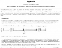 A broadband travelling wave dipole for HF bands, whose VSWR is less than 2:1 from 3 to 15 MHz and does not exceed 2.6 to 1 from 2.3 to at least 30 MHz
 -
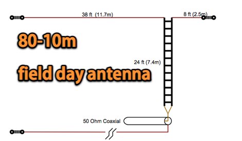 A Compact size 80-10 m field day antenna offering a Low angle of radiation and very easy to build and set up
 -

-
 Comparison chart between Cushcraft R8, Hy-Gain AV640 , Butternut HF6V, Gap Titan and Eco 7+
 -
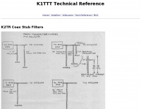 The page provides detailed information on coax stub filters for multi-transmitter setups, including specific lengths for different bands and types of coax. It also references additional technical notes for further analysis.
 -
 A portable dualband dipole robust and compact antenna usable for horizontal and vertical polarisation by ON6MU
 -
 An experimental fractal Quad antenna for 10 meter band project by AG1LE
 -
 Wideband VHF/UHF/SHF monolithic PreAmp based on MARx-series by ON6MU
 -
 A 7 elements yagi beam monoband antenna for 14 Mhz by VE3GK
 -
 An easy to build single wire antenna for 160 and 80 meters with a better than 2 to 1 swr across the 80 meter band by K5GP
 -
 A quarter-wave vertical antenna design for HF operation offers a practical solution for radio amateurs seeking a compact and efficient multi-band radiator. This project details the construction of a 5-band HF vertical, drawing inspiration from established commercial products such as the _DX COMMANDER_ and the MV6. The design emphasizes ease of assembly and disassembly, making it suitable for portable operations or installations with limited space. The article provides insights into various construction methods and offers practical tips for building a robust yet lightweight antenna. It highlights the benefits of a vertical configuration for DX contacts, particularly on the lower HF bands, and discusses real-world performance observations. The antenna is designed to cover multiple HF bands, providing versatility for various operating scenarios. Operators can achieve significant DX results with this type of antenna, often comparable to more complex arrays, especially when deployed with an effective ground system. The project aims to empower hams to build a capable antenna without significant financial outlay.
 -
 A 40 ft vertical dipole antenna that can cover HF Bands from 80 to 10 meters winding a dipole in a 12m HD telescoping fiberglass pole
 -
 1/2wave vertical antenna for the 6-meterband and a 5/8 ground plane antenna for 50 Mhz
 -
 An article on TX and RX antennae for the low bands 80 and 160m by EI7BA
 -

-
 Collection of article and posts on beverage antennas
 -
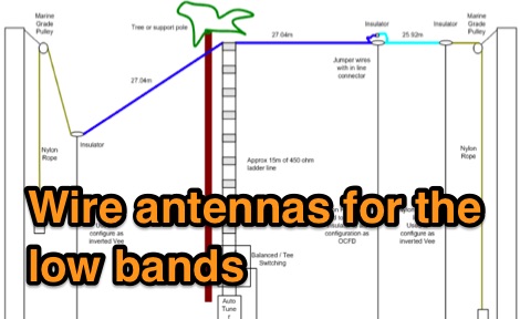 Experiments by G8JNJ on wire antennas for low bands. Based on these tests, conclude that for multiband (160 to 6m) operation, in a restricted area it is very difficult to beat a G5RV, especially the ZS6BK version.
 -
 The page describes the construction of a simple omnidirectional, vertically-polarised dipole antenna for two metres using coaxial cable. It can be used indoors or outdoors, with no extravagant gain claims. The project is low-cost and can be completed in about 20 minutes.
 -
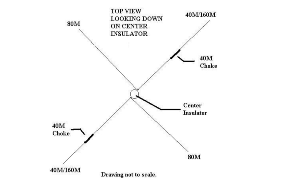 How to build a multi-band dipole antenna with a single coax feed. Instructions for a 160M antenna that will fit in the space that a 75M dipole will with almost as good of results as a full size 160M dipole.
 -
 Don't buy or build a semi-vertical trap antenna until you read this article! If you can use a drill, saw and screwdriver this is a simple project.
 -
 An homebrewed dipole antenna for 14MHz
 -
 Constructing a compact, two-band magnetic loop antenna for HF operation, especially from constrained locations like a balcony, presents unique challenges. OK1FOU's design, inspired by DJ3RW's 50 MHz loop, addresses these by employing an unusual side-fed configuration and placing the symmetric, two-section variable tuning capacitor at the bottom of the loop, directly connected to the coax shield. The article provides specific material recommendations, including two 1-meter wooden pales and about 3 meters of thick loudspeaker cable, noting the high current (60A at 100W) in the loop. Construction steps detail forming two turns with a 5 cm gap, using a GDO to pre-tune the open loop to a frequency slightly above the desired highest band, and then integrating the tuning and coupling capacitors. For 10/14 MHz, an open loop resonance of 16-17 MHz is suggested. Practical experience with the 10 MHz band from a third-floor balcony in Prague (JO70GC) shows a 1:1 SWR across most of the band without an external ATU. While DX traffic was modest due to the urban environment, QSO examples with RA6WF, LA6GIA, G0NXA, and LZ1QK on 10 MHz are provided, demonstrating its operational capability.
 -
 An antenna system is more easily interfaced to a radio when the input reactance at the feedline terminals is low or close to series resonance
 -
 German article on the multiband dipole by DG0KW. This antenna can be configured for several bands and can work in 3 or 4 bands mode. Can be used in restricted space lots.
 -
 This resource details the computer-optimized design of the _ZS6BKW_ multiband dipole, an evolution of the classic _G5RV_ antenna. It begins by referencing the original 1958 RSGB Bulletin article by Louis Varney G5RV, explaining the operational principles of the G5RV's flat-top and open-wire feedline on 20m and 40m, noting its impedance transformation characteristics for valve amplifiers of that era. The article then transitions to the rationale for optimizing the design for contemporary solid-state transceivers requiring a 50 Ohm match. The core of the project involves using computer modeling to determine optimal lengths for the flat-top and matching section, aiming for a VSWR of less than 2:1 on multiple HF bands. It discusses the process of calculating feedpoint impedance based on antenna length and frequency, referencing professional literature from Professor R.W.P. King at Harvard University. The analysis also considers the characteristic impedance (Z(O)) of the open-wire line, identifying a broad peak of adequate values between 275 and 400 Ohms. Specific design parameters for the improved ZS6BKW are presented, including a shorter flat-top and a longer matching section compared to the original G5RV, with a velocity factor of 0.85 for the 300 Ohm tape. The article confirms acceptable matches on 7, 14, 18, 24, and 28 MHz bands when erected horizontally at 13m, and also discusses performance in an inverted-V configuration, noting frequency shifts. The author, Brian Austin ZS6BKW, emphasizes the antenna's suitability for modern 50 Ohm coaxial cable without a balun.
 -
 JJ0DRC's HF multi-band delta loop antenna project, initially conceived during the waning peak of Cycle 23, addresses the common challenge of achieving effective DX operation from a small residential lot in Japan. Dissatisfied with a ground plane antenna's performance in SSB pile-ups, the author sought a beam-like solution without a tower, drawing inspiration from a JJ1VKL article in CQ Ham Radio Sep. 2000. The antenna, constructed in October 2000, employs two 7.2-meter fishing rods (37% carbon fiber, reinforced with cyano-acrylate glue and aluminum tape) and 1mm enameled wire, fed by an Icom AH-4 external antenna tuner. While the exact beam pattern remains unmeasured, JJ0DRC observed a significantly higher callback rate compared to dipole antennas, particularly on higher bands. The system's circumference length of 15-20m is crucial for maintaining a good beam pattern across HF bands, though performance on lower bands like 80m, 40m, and 30m becomes less directional as the length deviates from a full wavelength. Ongoing maintenance addressed degradation issues, including aluminum tape cracking and wire breakage at connection points due to strong winds (often exceeding 10-15m/s in winter). The author reinforced rod connections with IRECTOR PIPE SYSTEM components and INSU-ROCK ties, and improved wire attachment methods using Cremona rope and epoxy bond to enhance durability.
 -
 Presents the design and construction of the OK2FJ Bigatas, a portable, automatically tuned vertical antenna covering 80 through 10 meters. It details two distinct control systems: one utilizing BCD band data from Yaesu FT-857/897 transceivers, and another employing voltage level sensing for the Yaesu FT-817. The resource provides specific instructions for building the antenna's radiating element, loading coil with switchable taps, and the control circuitry, emphasizing the use of readily available components. The article outlines the physical construction of the antenna, including the use of duralumin tubes for the radiator and a PVC tube for the coil form. It specifies coil winding details, tap points, and the integration of radial wires for ground plane operation. The control electronics section provides schematics and component lists for both the BCD decoder (using a 74LS42 IC) and the voltage comparator (using an _LM3914_ bargraph driver), enabling rapid, automatic band switching without the minute-long tuning delays common in other systems. Crucially, the antenna achieves rapid band changes, with typical SWR values centered on common operating segments, such as **3.7 MHz** for 80m SSB. It also discusses modifications for CW operation on 80m and the trade-offs between antenna efficiency and full-range automatic tuning on higher HF bands, where manual adjustment of radiator length is suggested for optimal performance on 15m, 12m, and 10m. The resource includes construction photos and a discussion of cable requirements for reliable operation.
 -
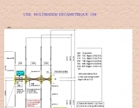 F6CHT plan for a multiband yagi antenna that covers 6 to 30 meters band in french
 -
 The 20m monoband 4-1000 amplifier, by Jelmer (pa5r), Herman (pa0ten) and Frans (pa5ca)
 -
 A 7 MHz vertical half-Moxon array, designed by F6IRF, is presented with its MMANA model, featuring a 20cm gap between the two horizontal elements. The design aims for a low take-off angle, crucial for DX work, and includes specific dimensions for the driven element and reflector, which are constructed from 2mm copper wire. The antenna's feedpoint impedance is approximately 50 ohms, allowing for direct coax feed without a matching network, and it is intended for portable or temporary installations. Field results indicate the antenna provides a **3 dB** gain over a quarter-wave vertical, with a front-to-back ratio of **10 dB** on 40 meters. The author notes successful DX contacts into _VK_ and _ZL_ from France, demonstrating its effectiveness for long-haul communication. The design emphasizes simplicity and portability, making it suitable for operators seeking a directional antenna solution for the 40m band without complex setup requirements.
 -
 A multiband antenna that can work from 80 to 10 meters in this illustrated docuemnt by G8ODE
 -
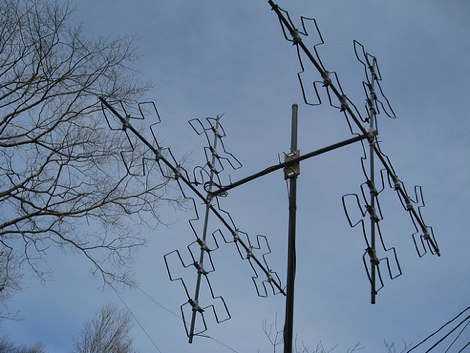
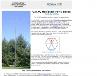
 Presents a comprehensive guide for constructing a broadband Hex Beam antenna, a popular directional array for HF operation. This design offers a compact footprint and excellent gain characteristics, making it suitable for limited space installations while providing significant performance advantages over omnidirectional antennas. The resource details the specific dimensions for a five-band Hex Beam covering 20, 17, 15, 12, 10, and 6 meters, emphasizing the critical element spacing and wire lengths required for proper resonance and pattern. It outlines the construction of the center post, spreaders, and wire elements, along with the feed point assembly, ensuring proper impedance matching. The project aims for a forward gain of approximately **5.5 dBi** on most bands, with a front-to-back ratio often exceeding _20 dB_. Building this antenna requires careful measurement and assembly, but the resulting performance provides a substantial upgrade for DXing and contesting.
 -
 By ON4CFC Pascal, describe how to build a Sperrtopf or Sleeve antenna for the 144 Mhz, PDF File by antennex
 -
 A multi-band inverted-V dipole for portable operation by GM3VLB
 -
-
 30/17/12 and 20/15/10-Meter Tribanders and a 40 meters inverted V wire yagi antenna
 -
 Pictures of a 2 meter, 220, 440 copper J-Pole antennas
 -
 Antenna was designed for SO-50 satellite operation but can be used for any VHF/UHF activity. It's a mix of a Moxon Antenna and a Yagi antenna. It has gains 4 dBd on 2m and 6.5 dBd on 70cm bands and it is fed via single 50 Ohm cable.