Search results
Query: Antenna
Links: 2481 | Categories: 254
This query is too generic. Please try adding an additional term to focus your research.
Categories
- Antennas > 20M > 20 meter Dipole Antennas
- Antennas > 20M > 20 meter Vertical Antennas
- Antennas > 20M > 20 meter Yagi antennas
- Antennas > 40M > 40 meter Delta Loop Antennas
- Antennas > 40M > 40 meter Dipole Antennas
- Antennas > 40M > 40 meter Loop Antennas
- Antennas > 40M > 40 meter Magnetic Loop Antennas
- Antennas > 40M > 40 meter Vertical Antennas
- Antennas > 40M > 40 meter Yagi Antennas
- Antennas > 6M > 6 meter J-Pole Antenna
- Antennas > 6M > 6 meter Moxon Antennas
- Antennas > 6M > 6 meter Yagi Antennas
- Manufacturers > Antennas > HF > Active antennas
- Software > Antenna analysis
- Manufacturers > Antenna Analyzers
- Radio Equipment > Antenna Analyzers
- Antennas > Antenna Books
- Antennas > Antenna Calculators
- Antennas > Theory > Antenna Gain
- Technical Reference > Antenna Launcher
- Manufacturers > Antenna Launcher
- Manufacturers > Antenna Masts and Mounts
- Shopping and Services > Antenna Mount
- Manufacturers > Antenna Parts
- Shopping and Services > Antenna Parts
- Technical Reference > Antenna Rotator
- Manufacturers > Antenna Rotators
- Software > Antenna rotor control
- Technical Reference > Antenna Switch
- Manufacturers > Antenna Switches
-
 This article discusses the Disk-Yagi antenna, also known as the "gun antenna," popularized by the video blogger KREOSAN. It explains the design, differences from standard Yagi-Uda antennas, and key features like the use of patch antennas and the integration of MIMO technology. The article covers the construction, tuning challenges, scaling issues, and provides insights on practical applications, such as optimizing signal performance with a 75-ohm antenna. It emphasizes that while DIY versions may vary, careful tuning and design are crucial for effectiveness.
 -
 Author found a ratio between the lengths of the sides of the Delta Loop that give reasonably low SWR into a 50 ohm coaxial cable almost independent of the high above ground and other surroundings. This ratio also gives good results no matter orientation. Includes an online delta loop antenna calculator.
 -
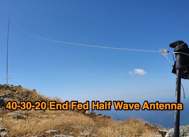 For my SOTA activities, i recently bought a QRP transceiver QRP SW-3B, which is a three-band QRP CW only for 40/30/20 m. So, i needed an antenna that would allow to use these 3 bands in SOTA portable activity. Already having some experience with the EFHW antenna, i decided to build one for 40/30/20m.
 -
 This antenna is reported as being lower noise than conventional yagis and had a very low SWR for 500 KHz.
 -
 This small dual band UHF VHF directional antenna is good choice for portable operations. This antenna is composed by a moxon antenna for the two meters band and it includes two parastatic elements for 70 cm band.
 -
 Operating in antenna-restricted communities presents unique challenges for amateur radio operators, often necessitating creative solutions for antenna deployment. This resource details the design and implementation of stealth antennas within a townhouse community in Exton, PA, where external antennas were strictly forbidden by covenants. The author, WB5NHL, describes his setup, which involved locating the shack in the basement and utilizing an unused space under the roofline of a finished third-floor loft for antenna placement. The content specifically addresses the practicalities of routing coax cables three floors and maximizing antenna performance within limited attic space. It covers solutions for multi-band operation, including dedicated sections for 40-10 meter and 80-meter antennas, along with strategies for mitigating potential interference issues. The approach emphasizes full compliance with community covenants, achieving maximum height-above-ground for horizontal antennas, enabling instant band switching, and efficiently utilizing available attic volume. While acknowledging limitations such as potential interference with high power and fixed antenna patterns, the resource provides a detailed account of a functional compromise for restricted environments. Links to individual pages on _coax cables_, _40-10 meter antennas_, _80-meter antennas_, and _interference issues_ offer deeper dives into each specific aspect of the installation.
 -
 A hexagonal beam is a form of the Yagi antenna which is based on parasitic principles developed early in the last century in Japan for achieving gain in one direction.How HexBeam antennas works. A hexagonal beam operates exactly like Yagi antenna, but instead of a driven element that is straight like a dipole, it is a wire bent into the shape of the letter M.
 -
 A mircovert antenna assembled for the 40m version of the DL7PE antenna. A one meter long aluminum tube with 24mm diameter is used for the base (element 1) and a 50cm aluminum tube with 20mm diameter for element 2 (the extention). A pvc pipe, 34cm long and with a diameter of 38mm, is used to wind the coil on (1mm enamelled copper wire).
 -
 Coax Velocity Factor in Baluns, Does it Matter? Test results show coaxial cable velocity factor does not always enter into stub length calculations especially in the world of Baluns
 -
 Essentially, a J-pole is a 1/2 wave resonant antenna connected to a quarter wave matching stub. The feedline is connected at a point on the matching stub that is at the feedline's characteristic impedance. The result is 3/4 of a wavelength on one side and 1/4 wavelength on the other side.
 -
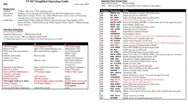 A simplified operating guide for the Yaesu FT-817
 -
 The PAC-12 Antenna, a multi-band portable vertical, is meticulously detailed in this construction article by James Bennett, _KA5DVS_. The design emphasizes ease of homebrewing using readily available components from local hardware stores, including replaceable loading coils. It outlines the preparation of the 72-inch telescoping whip (originally from Radio Shack, with an alternate source now provided by _Pacific Antenna_), the construction of the loading coils from PVC risers, and the fabrication of the aluminum rod base sections. Specific instructions cover threading aluminum rod with a _1/4-20 threading die_ and assembling the feedpoint insulator with a BNC connector, along with recommendations for radial deployment. KA5DVS, an avid traveler and QRP enthusiast, developed the PAC-12 to address the bulkiness of random wire setups and the limitations of commercial portable antennas like the Outbacker or SuperAntennas MP1. His goal was a lightweight, packable antenna that disassembles into 12-inch sections, achieving an assembled length of approximately 8 feet. The design strategically places the loading coil away from the base for improved efficiency. The PAC-12 notably placed first in efficiency compared to a quarter-wavelength wire vertical at the HFPack antenna shootout during the Pacificon conference in October 2001, demonstrating its practical performance for field operations. Appendix C showcases various _NJQRP Club_ members' PAC-12 constructions, including a 20m beam made with multiple PAC-12 elements.
 -
 2 Wavelength ,2 Meter Bi-Square Beam , 5dbd gain. This antennas are very cheeap to build and their radiation pattern is similar to a figure 8 with maximum signal through the loop but they may be used as a near-omnidirectional antenna
 -
 Building an 80-160 meter antenna in a small garden (9m x 14m) involves creative solutions due to space constraints. This project outlines the construction of a trapped 80-160 meter vertical dipole, utilizing a crank-up tower and an 11-meter fiberglass pole. The design prioritizes minimal visibility, ease of construction, and cost-effectiveness, achieving effective operation despite limited space.
 -
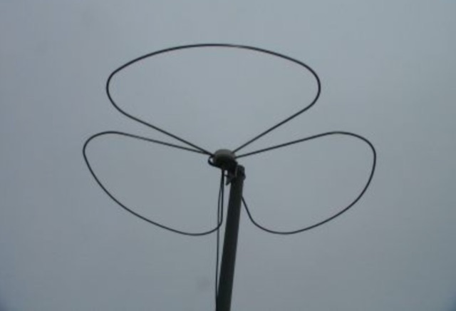 An omnidirectional horizontal polarization antenna for 2 meters band in Italian
 -
 This page describes a couple of parts box medicine bottle antennas that you can build. The ground side of the capacitor is soldered to the ground of the BNC connector. The positive side of the capacitor takes 5 turns around the toroid and is soldered back to itself. The center pin of the BNC connector takes 5 turns around the toroid and then continues on to the wire wound inductor. From there the antenna continues with an attached piece of wire.
 -
 Hy-Gain TH3jr Tri-band HF 3 Element Beam Covers 10, 15 and 20 Meters assembly instruction manual
 -
 You can bend the wires in a half-wave dipole so that it takes up less space, with minimal loss of efficiency.It is advisable to get the ends of the antenna as high as possible, especially if children and animals are kept in the area around the antenna, as there are very high tensions on the ends of the antenna during transmission! In Norwegian
 -
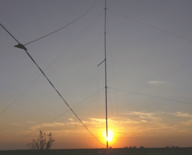
 This article describes a simple yet effective multi-band vertical HF antenna design that performs exceptionally well across 80m to 10m bands. The antenna consists of a 13.4m wire mounted on a 12.4m Spiderpole, complemented by four 12m radials and a ground rod. Initially tuned with a manual LC circuit, it was later upgraded with a CG3000 remote auto ATU for convenient band switching. Despite antenna modeling software suggesting limited performance on higher frequencies, the system demonstrated excellent DX capabilities across all bands, outperforming more complex vertical antenna designs.
 -
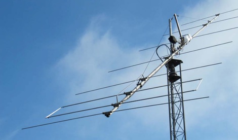
 Experimental Long Boom Antennas - CP, LPDA, multiband with several NEC Files for 50MHz 144MHz 222 MHz 432MHz but also 902MHz and 1296 MHz Antenna projects. Includes also for each antenna model, in a general comparison table each antenna characteristics including Directive Gain, G/T, E-F/R, H-F/R abd Boom Length. This is a great value comparison table of several commercial and home made VHF UHF antenna projects.
 -
 This PDF document reviews the POTA PERformer Antenna by KJ6ER, providing insights and details about its performance and features. The content is aimed at hams looking for information on this specific antenna model to help them make an informed purchasing decision. It contains technical specifications, user experiences, and possibly recommendations for optimal use. The review is valuable for hams interested in portable operation and seeking a reliable antenna solution for Parks on the Air (POTA) activations.
 -
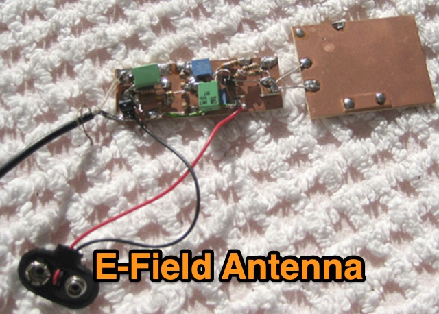 A small active voltage probe antenna to aid reception on the LF bands
 -
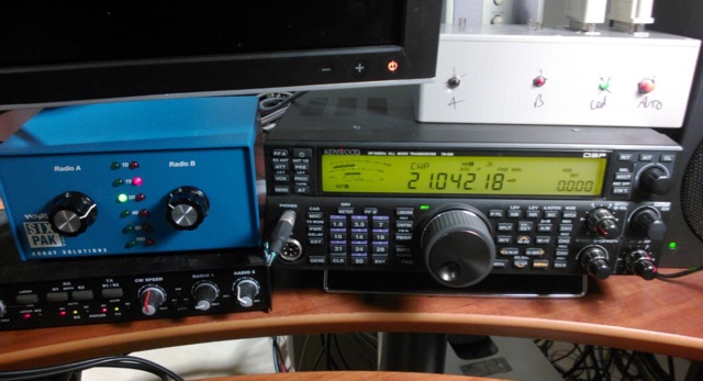 In pursuit of enhanced station efficiency, the author describes crafting an Arduino-based smart antenna switcher for an SO2R setup. Faced with manual antenna switching challenges during contests, the project utilizes a Logos Electromechanical 4x4 Driver Shield and a Power Screw shield for seamless functionality. Despite its raw appearance, the automatic switcher proves indispensable in contest scenarios, prompting considerations for future improvements and standardization of station control protocols.
 -
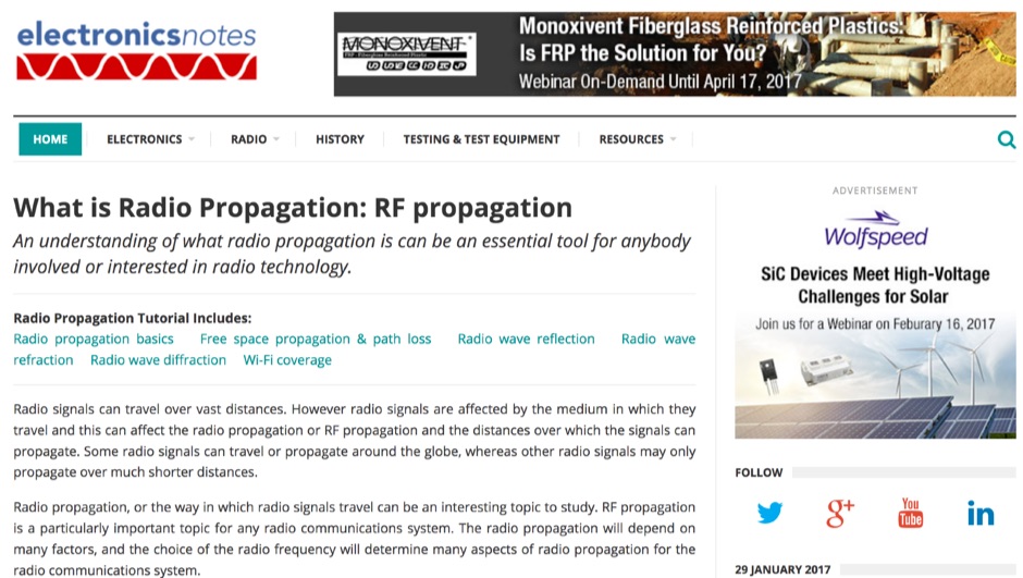 Discover the key facts about what radio propagation is, the different types available and how they affect different frequencies.
 -
 A j-pole antenna plan with drawings and dimensions that can help you on building your own j-pole antenna for the six meters band
 -
 A simple 6dBi Collinear Antenna for LoRa compared to the Lorank8 gateway default antenna.
 -
 Results or performance test using an harpin antenna for the 7 MHz
 -
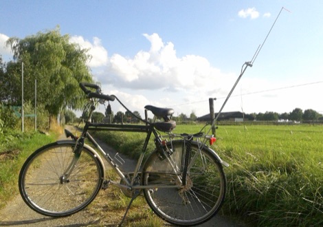 Homebrewing a UHF antenna to be used on a bicycle. This simple project gives you the right hints on how to build and setup and install a 70cm antenna on a bicycle.
 -
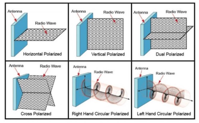 What is antenna polarization, and why does it matter. Horizontal versus Vertical versus Circular polarization. Undestanding how antennas perform better with different polarizations.
 -
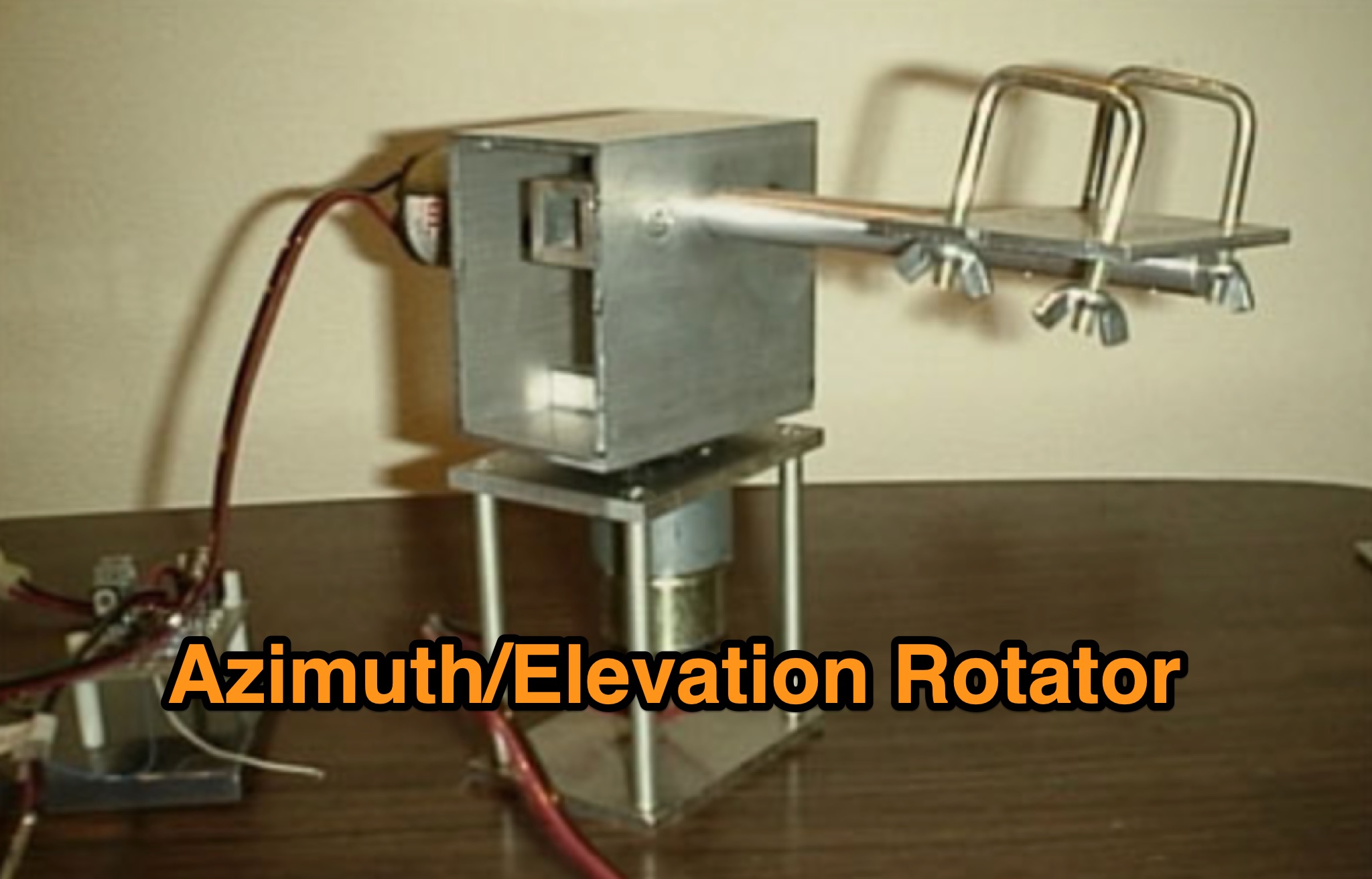 Learn how to build a simple 12vdc azimuth and elevation motor unit for the Arrow Satellite Antenna to improve your FM satellite communication experience. This DIY project involves using a camera tripod and basic materials like aluminum tube and standoffs. Get detailed instructions, including the gearhead motor product number for optimal performance. Discover where to purchase the necessary components and stay updated on alternative motor options. Enhance your ham radio operations with this homemade rotator setup, designed for easy satellite tracking and communication. Share feedback and connect with other radio enthusiasts for more tips and ideas.
 -
 An article about the Beverage antennas, super long wire receiving antennas thar are unidirectional and have a very low noise that makes this antenna excellent for low band dxing. By Thomas R. Sundstrom W2XQ, 73, June 1981, 73 Magazine
 -
 This article shares the author's experience with building antennas. After putting a large magnetic loop project on hold, they decided to try a base-loaded vertical antenna. The author explains how they chose to design a new antenna from scratch, aiming for a frequency of 7 MHz. They describe the calculations needed to find the right coil inductance and how they used 3D-printed parts for the construction. The article wraps up with results from their initial tests, showing good communication on different bands and highlighting the success of their design.
 -
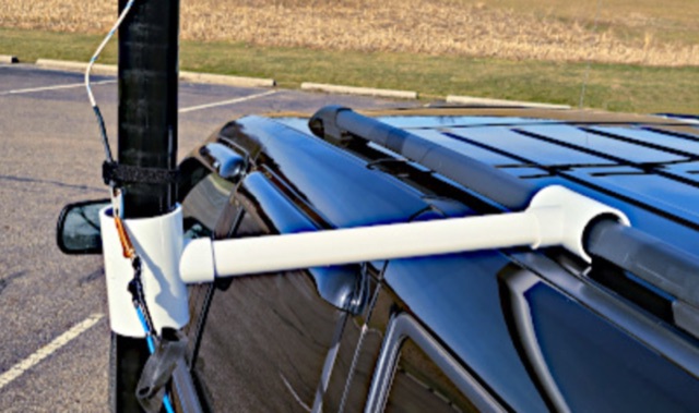 This antenna mast mount uses two Reese hitch extensions that are welded on to a piece of 2 inch square tube. It comes apart in two pieces. The vertical pipe on the left is welded on to a 2 inch piece of square tube that fits into the Reese hitch extension.
 -
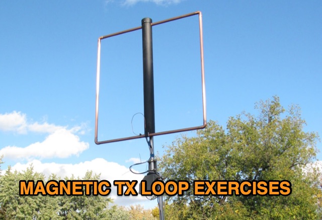 Explore two magnetic loop antenna constructions, utilizing a 6-foot and a 12-foot square loop. Accompanied by a detailed description, the 6-foot loop features a built-in stepper motor control circuit, while the 12-foot loop incorporates a separate loop controller. Efficiency, tuning ranges, and the innovative autotuning solution using a microcontroller are discussed, offering insights into overcoming the antenna's narrowband limitations.
 -
 Pro-cell Co., Ltd was established in 1995 to produce and develop wireless components. In the beginning stage, we concentrated on producing GSM antennas, now produce Commercial- RFID, GSM UMTS GPRS LTE WLAN Wi-Fi Wi-Max, PMR & Tetra antennas
 -
 A Lightweight 2m Yagi for SOTA. The boom is 20mm PVC electrical conduit and the elements are 2.4mm aluminium TIG welding rod. The antenna is carried as a single length of conduit with the elements stowed inside the boom, sealing them in with a bung. The driven element is connected directly to 50 Ohm coax with a BN-43-202 balun core to decouple the coax shield.
 -
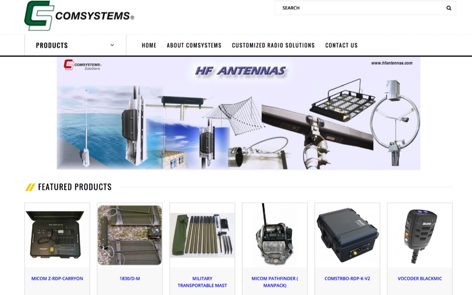 HF Antennas is a division of Comsystems Solutions we manufacture wire broadband antennas and different type.
 -
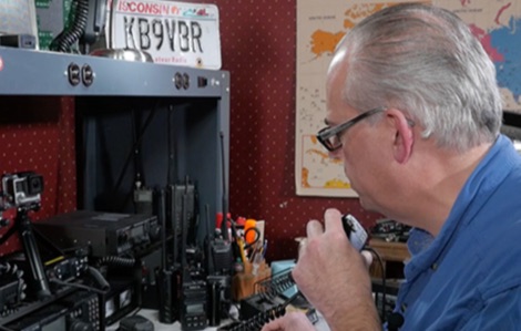 A great way to provide a public service and maintain your skill as an operator is to be a net control station. Being net control is rewarding and not overly difficult.
 -
 The original HEXBEAM was developed by Mike Traffic, N1HXA, in the early nineties. It is true that an M over W configured yagi antenna that resembled a butterfly was earlier tried successfully. But the advanced electrical design, the characteristic nesting concept and central terminal post that enable the multi band functionality along with the basic hardware design were all developed by Mike Traffie.
 -
 This article provides details on building a 6 Meter J-Pole antenna using PVC pipe for an enclosure.
 -
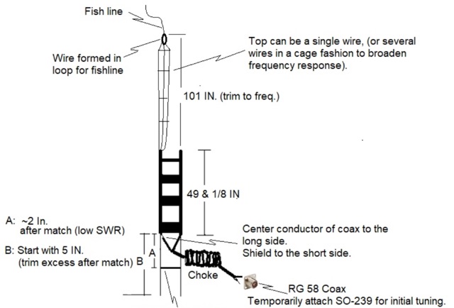
 Experimentin wire antennas on top band using several type of aerials. This includes a 40 to 160 meters EndFed Half Wave kite antennas and 160m/80m loaded vertical antenna.
 -
 Here is a formula and calculator for creating a loaded (shortened) quarter wave vertical or balanced dipole. The calculation refers to either a loaded 1/4 wave or a loaded dipole
 -
 Operating marine mobile with antennas for 15-17-20 meters band.
 -
 Extended Double Zepp measurements for all ham bands, and online calculator. The antenna is constructed much like an ordinary Dipole antenna but with 5/8 Wavelength Elements matched with an added Impedance Matching Section of balanced feed line
 -
 This page by Keith Greiner describes a magnetic loop antenna project, providing step-by-step instructions to create two versions of a system with one large loop and one small loop. It includes details on how to construct the loops using different materials, along with the necessary equipment like antenna analyzers, tuners, and software. The page is divided into five sections covering project discussion, design summary, an improved small loop, construction steps, and radiation pattern analysis. Aimed at hams interested in building their own magnetic loop antennas, the page offers practical guidance and insights into impedance matching for improved performance.
 -
 Learn how to easily build a 10-meter vertical antenna, perfect for DX contacts on the amateur radio bands. This flowerpot or T2LT design is portable, efficient, and ideal for ham radio operators looking to improve their DX performance. With just a few basic tools and materials, you can construct this antenna for portable operations or as a home station setup. Discover how to set up the antenna, improve its performance by raising it higher, and start making contacts with stations around the world. Watch a step-by-step guide on YouTube for building and testing this DIY ham radio antenna.
 -
 A dual band 40-80 vertical antenna on an 18m Spiderbeam Fiberglass Spiderpole, with monoband performance
 -
 This antenna looks like an inverted L antenna, yet it is not, it could also be viewed as a 160m off-center fed dipole antenna, it looks more like an end-fed 1/4 wave 160 meter antenna.
 -
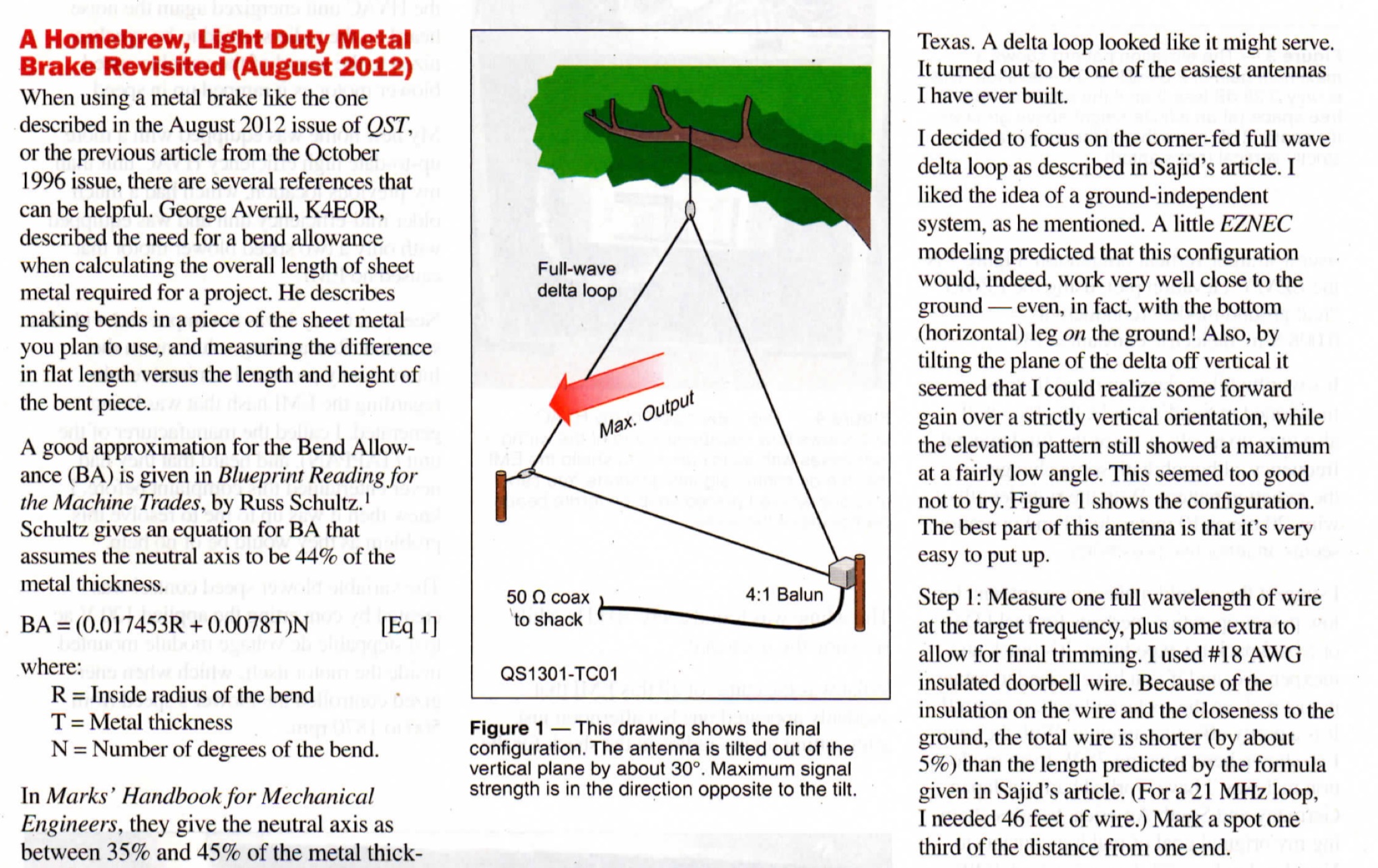 This guide provides step-by-step instructions on how to install a delta loop antenna for hams. It covers the necessary materials, tools, and installation process in a clear and concise manner. Whether you're a beginner looking to set up your first antenna or an experienced ham radio operator wanting to try a new antenna design, this guide is a valuable resource to enhance your radio communication setup.
 -
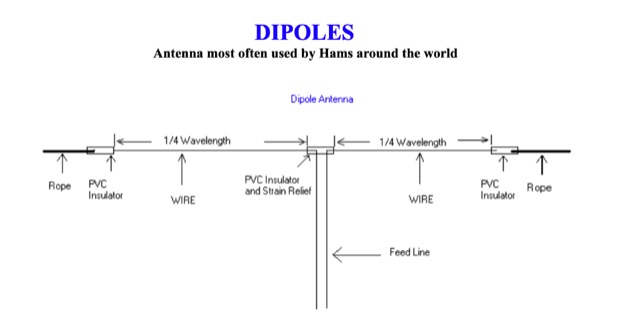 Antenna most often used by Hams around the world. Inexpensive, effective and easy to build, what more could anyone ask for in a home made antenna.