Search results
Query: HF antenna
Links: 899 | Categories: 40
Categories
- Radio Equipment > HF Vertical Antenna
- Radio Equipment > HF YAGI Antennas
- Shopping and Services > Antennas > VHF Antenna
- Radio Equipment > HF Portable Antenna
- Radio Equipment > HF Vertical Antenna > Butternut HF2V
- Manufacturers > Antennas > VHF UHF Microwave > Discone Antennas
- Manufacturers > Antennas > HF
- Manufacturers > Antennas > VHF UHF Microwave > Mobile Antennas
- Manufacturers > Antennas > VHF UHF Microwave > Quad Antennas
- Manufacturers > Antennas > HF > Quad Antennas
- Manufacturers > Antennas > HF > Small & Stealth Antennas
- Radio Equipment > HF Portable Antenna > Super Antennas MP-1
- Radio Equipment > HF Portable Antenna > TransWorld Antennas TW2010
- Manufacturers > Antennas > VHF UHF Microwave > Vertical Antennas
- Antennas > VHF UHF
- Manufacturers > Antennas > VHF UHF Microwave > Yagi Antennas
- Manufacturers > Antennas > HF > Yagi Antennas
- Manufacturers > Antennas > VHF UHF Microwave
- Manufacturers > Antennas > Broadcast
- Antennas > CobWebb
- Antennas > Collinear
- Radio Equipment > HF YAGI Antennas > Cushcraft A3S
- Radio Equipment > HF YAGI Antennas > Cushcraft MA5B
- Radio Equipment > HF Vertical Antenna > Cushcraft R5
- Radio Equipment > HF Vertical Antenna > Cushcraft R7
- Radio Equipment > HF Vertical Antenna > Cushcraft R8
- Antennas > Handhelds
- Radio Equipment > HF Vertical Antenna > Hustler 5-BTV
- Manufacturers > Antennas > HF > Magnetic Loop
- Radio Equipment > HF Vertical Antenna > Maldol MFB-300
-
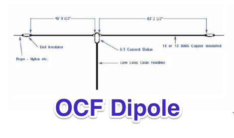 This is a popular antenna design as the performance is very good across the HF bands and requires little or no tuning. It is a dipole fed off center with a 4:1 current balun at the offset feedpoint. The antenna shown covers 80, 40, 20 and 10 meters with 15 meters and WARC bands
 -
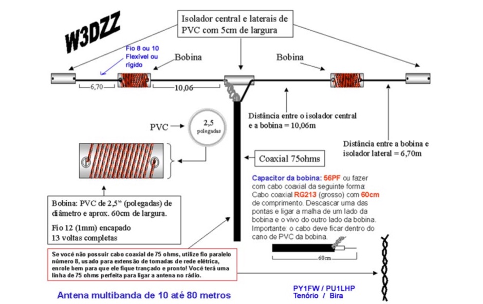 A schematic design of the W3DZZ antenna in portugues with description of trap building
 -
 The MFJ-940 VERSA TUNER II is a useful little antenna tuner for the HF-bands. However it suffers from a minor design error, which can be easily rectified.
 -
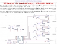 This resource details the construction of a versatile CW/QRSS beacon, designed around a Microchip _PIC16F84_ microcontroller. The project provides a flexible platform for transmitting either standard CW or very slow QRSS signals, making it suitable for LF, VHF, UHF, and SHF applications. It supports two distinct messages, each configurable for speed (from 0 to **127** WPM for CW, or up to **127** seconds per dot for QRSS) and repetition within a six-phase sequence. The core functionality relies on the PIC's EEPROM, which stores all operational parameters, including message content, transmission speeds, phase configurations, and relay control settings. This design allows for parameter modification directly via programming software like _ICProg_ without altering the main program code. The project includes a detailed schematic, a component list, and an explanation of the EEPROM memory mapping for messages, speeds, phase settings, and inter-phase delays. General-purpose outputs (OUT1, OUT2, OUT3) provide dry relay contacts for external control, enabling functions such as power switching, antenna selection, or frequency changes. A 'TRIGGER' input facilitates controlled starts or continuous free-run operation. Sample EEPROM configurations illustrate how to program specific beacon sequences, including message content and relay states.
 -
 Illustrates the specific wiring and configuration steps required to interface an SGC-230 Smartuner with an Icom IC-706 HF/VHF/UHF transceiver. The document details the necessary connections for power, control, and RF signal paths between the two devices, ensuring proper impedance matching and automatic antenna tuning functionality. It specifies the pin assignments for the IC-706's ACC socket and the SGC-230's control port, crucial for successful integration. Outlines the operational considerations for the combined system, including initial setup procedures and potential troubleshooting tips for common connectivity issues. The resource presents a clear, diagrammatic representation of the interconnections, which aids in visual comprehension of the required cable fabrication or modification. Covers the specific settings within the IC-706 menu that need adjustment to enable external tuner control, such as the 'TUNER' function and other relevant parameters. This ensures the transceiver correctly communicates with the SGC-230 for efficient antenna tuning across various amateur bands.
 -
 The Q-signal **QRP** signifies a request to reduce power, and in amateur radio, it defines operating with 5 watts or less for CW and 10 watts or less for SSB. This article addresses common inquiries from new hams regarding the practice, its benefits, and implementation methods. It explains how a 5-watt QRP signal, compared to a 100-watt signal, typically results in only a 13dB drop in signal strength, equating to about two S-units, still providing solid copy under most conditions. Hams choose QRP for various reasons, including seeking a greater challenge in DXing or contesting, reducing band interference, or enabling portable field operations with lightweight, battery-efficient equipment. A modern single-band CW transceiver, key, and antenna can fit into a pocket, offering receiver performance comparable to commercial rigs and extended operation on a small battery. This portability facilitates operations in remote locations where higher-power setups are impractical. Operating QRP can involve simply reducing power on an existing commercial HF rig or building a dedicated QRP transceiver from a kit, such as the **Wilderness Radio SST** with its 2-watt output and 15mA receive current draw. While SSB is viable, CW remains the most popular and efficient mode for QRP due to its superior signal-to-noise ratio. The article lists common QRP calling frequencies across 160m through 10m bands for both CW and SSB, and highlights organizations like QRP ARCI and NorCal that support the QRP community.
 -
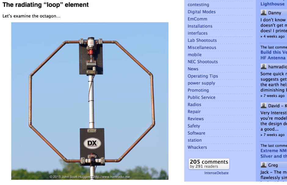 A well documented article on a small magnetic loop antenna for the 40 meters band
 -
 The ZS6BKW wire antenna, a variant of the G5RV, utilizes a specific 13m (42.6 ft) length of 450-ohm window line as its matching section, feeding a 28.5m (93.5 ft) flat-top element. This design aims for lower SWR on 40m, 20m, 17m, 12m, and 10m compared to a standard G5RV, often achieving SWR values below 1.5:1 on these bands without an antenna tuner. The feedpoint impedance transformation provided by the window line allows for direct connection to 50-ohm coax on multiple bands. F4FHH's experience involved constructing the ZS6BKW and evaluating its performance against an _OCF dipole_ (Off-Center Fed) on various HF frequencies. The article includes observations on SWR readings and operational effectiveness, highlighting the ZS6BKW's suitability for multi-band operation. The antenna's overall length, including the flat-top and window line, is approximately **41.5 meters** (136 feet), making it a significant wire antenna for fixed station use. Comparative analysis with the OCF dipole provided practical insights into the ZS6BKW's advantages and limitations, particularly concerning bandwidth and tuner requirements.
 -

-
 Multiband no trap no gap antenna. This Antenna is a small wonder, easy to build and allow you to work all HF spectrum with your TRX and it's internal ATU.
 -
 Presents the Light Loop, a small magnetic loop antenna optimized for 40m through 10m operation, demonstrating its construction for portable QRP use. The design emphasizes lightweight materials and a compact form factor, making it suitable for handheld or backpack deployment during field activities. It details the primary radiating element, the coupling loop, and the variable capacitor required for resonance across the specified HF bands. The article provides specific component choices, such as the 1.5-inch diameter aluminum tubing for the main loop and the 10-365 pF variable capacitor for tuning. It discusses the importance of precise loop circumference and spacing for efficient impedance matching and bandwidth characteristics. The resource includes practical advice on achieving resonance and optimizing performance for low-power transceivers. Construction notes cover the mechanical assembly, including mounting the capacitor and feedpoint connections. It highlights the antenna's suitability for pedestrian mobile operations, offering a practical solution for HF communication without extensive setup. The design aims for a balance between portability and effective radiation on the lower HF bands.
 -
 The AMRAD Active LF Antenna. You can tune into LF activity with this easy-tobuild and erect active antenna. As a bonus, you get MF and HF coverage, to not to mention world-class performance
 -
 Demonstrates the iterative design and construction of a **tapped HF/VHF mobile vertical antenna** by K0EMT, detailing four generations of development. The antenna supports operation on 80m, 40m, 30m, 20m, 17m, 15m, 12m, 10m, 6m, and 2m bands. Initial designs, like Generation 1, featured a 3/8" x 24TPI bolt in a PVC end cap with a 1" aluminum tubing mast, resulting in a 9'9" overall length and resonance around 6.9 MHz with the full coil. Subsequent generations refined the mast and coil forms, transitioning from aluminum to copper tubing (Generation 3, found too weak) and eventually fiberglass for the coil form (Generation 4, in progress). Coil tapping points were adjusted to achieve resonance without an external tuner in Generation 2. The project outlines material costs, totaling approximately $25, and mentions a successful 28 MHz QSO with EA3XA using an ICOM IC-706 mk II at 100 Watts. For 80m operation, an external wire with the maximum coil setting is used, or a 56" extender below the coil for stationary use.
 -
 Presents the detailed construction of the _FLA25HV_ antenna, a specialized array optimized for Earth-Moon-Earth (EME) communications on the 2-meter band. This resource provides schematics and practical insights into building a high-gain antenna system capable of reflecting signals off the lunar surface, a challenging but rewarding aspect of amateur radio. It covers the mechanical and electrical considerations essential for achieving the precise pointing and signal strength required for successful moonbounce contacts, often yielding **20 dB** or more gain. Amateur radio operators pursuing EME operations require robust antenna systems and precise tracking capabilities. The FLA25HV design addresses these needs by focusing on element spacing, impedance matching, and structural integrity to withstand environmental factors while maintaining critical alignment for lunar reflections. Such systems are crucial for making contacts over distances exceeding **768,000 km**. This personal page serves as a practical guide for hams interested in constructing their own EME arrays, offering a glimpse into the technical dedication involved in pushing the boundaries of VHF/UHF propagation.
 -
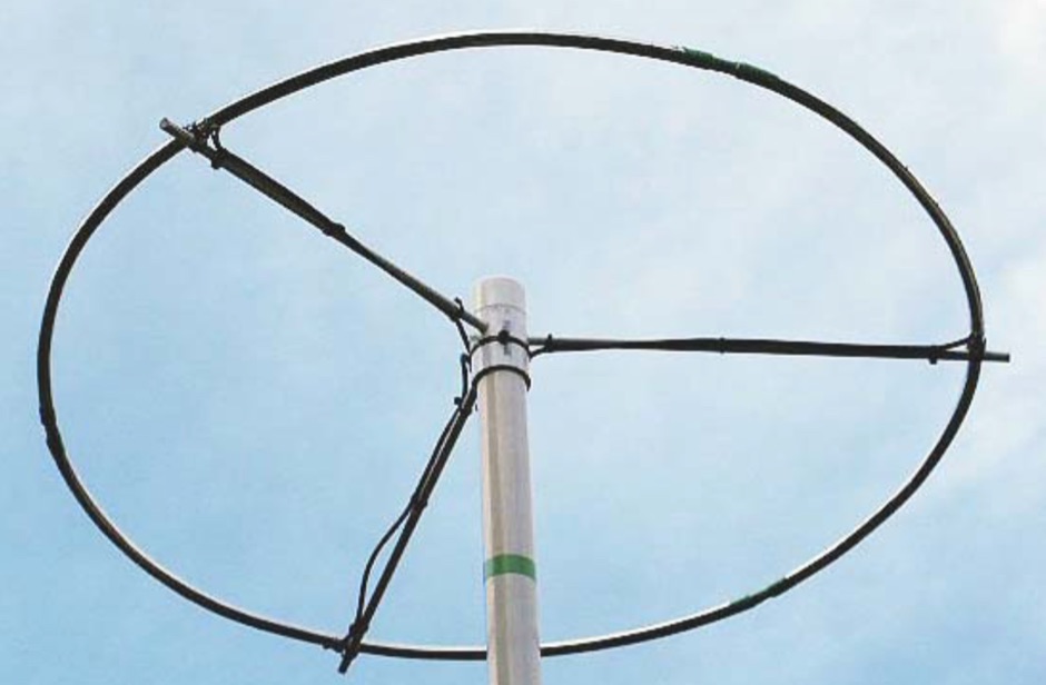 A popular 2 meter antenna returns in an improved, easier to reproduce form, 2008 QST article
 -
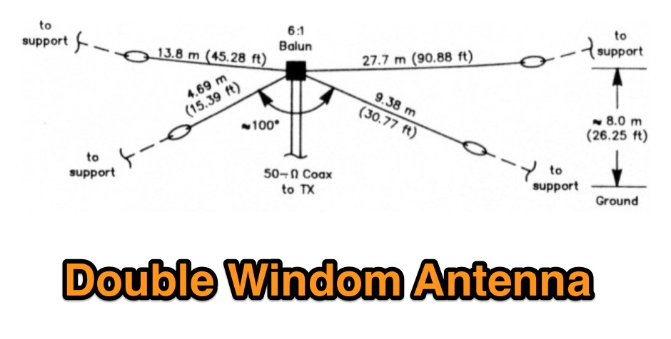 A project for a multiband HF windom antenna by VE2CV and VE3KLO
 -
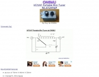 A small portable antenna tuner for HF and VHF bands by ON6MU
 -
 This resource details the construction of a mobile screwdriver antenna, patterned after the original W6AAQ DK3 design from 1991. It covers the mechanical and electrical aspects of building a robust, multiband HF antenna for vehicular operation. Specific components discussed include the lower mast section, the coil wound on Schedule 40 PVC pipe, beryllium copper contact fingers, the motor drive assembly utilizing a Black & Decker screwdriver, and the capacity hat design with a brass hub and steel wires. The article provides insights into material selection, such as heavy copper tubing and silicone grease for assembly, and addresses practical considerations like coil length limitations for 80m operation due to lathe size. The construction results in an antenna capable of tuning from 6.5 MHz (40m) up to 6m, with slightly reduced range when the capacity hat is installed. The author describes the mounting base with soldered brass nuts for secure attachment and a U-channel bracket for vehicle mounting on a Dodge Ram 1500. The article includes close-up photographs illustrating the coil, contact fingers, drive mechanism with rubber tubing clutches, and the capacity hat assembly. It also mentions the use of Rustoleum hammer finish enamel for painting the copper pipe, indicating attention to durability and aesthetics.
 -
 Local and DX contacts from tight spaces, it works from 40 to 17 meters
 -
 Constructing a high-gain, compact antenna for 2 meters often involves balancing theoretical performance with practical build challenges. WB8AHT recounts his journey in building a 6-element _Super Duper Moxon_ antenna for 144 MHz, inspired by designs from M0PXS and GW3YDX. He initially encountered discrepancies in published dimensions for the _HAARP Antenna_ and the _Super Moxon_, leading to on-air SWR issues and suboptimal performance. His methodical approach involved cross-referencing, direct communication with Phil Simpson (M0PXS), and iterative adjustments to element lengths based on observed results and a _SARK-110 Antenna Analyzer_ scan. After modifying the reflector/driven element and third director dimensions, the antenna achieved a respectable 1.35:1 SWR at 144.200 MHz. Field testing with 50 watts yielded contacts up to 500 miles, suggesting performance close to the 15 dBi gain predicted by _4NEC2_ software, despite its compact 40-inch boom. The article includes specific construction notes, such as tubing sizes (1/2-inch and 3/8-inch aluminum) and feedpoint spacing (50mm). The author's experience highlights the importance of real-world validation for antenna designs, even those with strong theoretical backing. He provides a table of tubing lengths for 6m, 4m, and 2m versions, along with his final, optimized dimensions, offering a practical blueprint for fellow hams interested in replicating or further experimenting with this high-performance, small-footprint VHF antenna.
 -
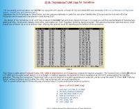 Based on DL6UW Yagi antenna's design-formula The forward gain is 13.6 dBi (about 11.5 dBd) and it's pretty small, about 1,5 m in length
 -
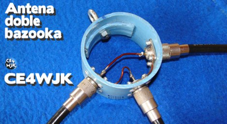 A page dedicated to the doble bazooka antenna with dimensions for all HF bands
 -
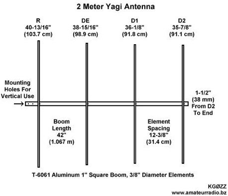 An interesting article on building a 4 elements yagi antenna with gamma match for the 2 meter band. This article include two videos demonstrating assembling procedure by KG0ZZ
 -
 Demonstrates the construction of two distinct wideband RF preamplifiers, detailing their component requirements and performance characteristics. The first design leverages monolithic microwave integrated circuits (MMICs) such as the MAR-6, MAR-8, or PGA103, offering a broad frequency response from DC to 2 GHz with a gain of 22.5 dB at 100 MHz and a noise figure typically below 3 dB. This MMIC-based amplifier incorporates protection against power supply transients and features a 50 Ohm input/output impedance, operating from an 8-20 volt supply with low current drain. The second preamplifier design utilizes a BSX-20 transistor, providing amplification across the 14 MHz to 550 MHz range. This simpler, more economical build achieves an average gain of 12 dB at 145 MHz and a noise figure of approximately 1.1 dB. It operates from a 7-15 volt battery supply with a current draw of 6 mA. Both projects emphasize critical construction techniques, such as maintaining short RF connections, ensuring 50 Ohm impedance paths, and mounting the circuit within a shielded enclosure to optimize performance and minimize noise. The resource also discusses phantom power options for antenna-mounted preamplifiers and precautions for use with transceivers, including output protection diodes and static bleeders.
 -
 Multiband and monoband HF Vertical antennas and rotatable dipoles manufacturer based in Texas USA
 -
 A monoband end-fed half wave for 10m, 20m or any other HF band, includes a PDF with detailed information to build your own monoband or multiband antenna
 -
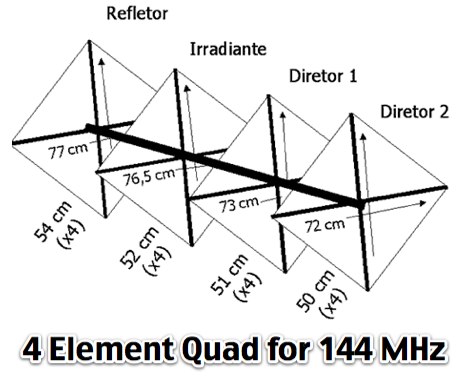 A project for a four element cubical quad antenna for 144 MHz in portuguese
 -
 Here is an antenna for the nineties. It's strong, computer designed, and has lots of gain. It is a full size, four element beam on 10, and three elements on 15 meters
 -

-
 The QRP choke balun described utilizes a high permeability ferrite rod and RG-174 coax, aiming to present high impedance to common-mode currents across the HF spectrum. The construction involves winding as many turns of RG-174 as possible around the ferrite rod, then encapsulating the assembly with hot glue. This design prioritizes maximizing inductance to suppress unwanted shield currents, particularly in unbalanced antenna configurations. While the balun's effectiveness is subjectively reported as good, a potential design consideration involves the dielectric properties of the hot glue. This material could increase turn-to-turn capacitance, potentially reducing the balun's performance at higher HF frequencies, though this specific aspect has not been formally tested by the author, _AA5TB_. The project serves as an illustrative example of a practical, junk-box construction rather than a rigorously engineered solution. Photographs detail the evolution of the balun, from the initial winding process to its integration within a _B&W dipole center insulator_ and final camouflaged assembly.
 -
 Low Noise Antenna pre-amp for SAT, EME & DX-ing
 -
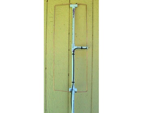 Presents the construction and performance characteristics of a **2-meter vertical Moxon** antenna designed by WB5CXC. The antenna utilizes 1/2-inch PVC and #6 copper ground wire for its physical structure. Performance data includes measured front-to-back ratio using a local repeater, demonstrating significant signal attenuation when rotated. The resource provides **antenna pattern** plots, with blue tracing the design at 146 MHz and red indicating performance at 148 MHz. Gain and SWR plots are also included, alongside a detailed diagram of the antenna's physical layout. The design emphasizes a good front-to-back ratio, aligning with modeling predictions.
 -
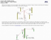 Different band dipoles can be put together with a single feed, learn how by W8HDU
 -
 The antenna is an inexpensive, multiband, end fed HF antenna. It has a matching network consisting of a toroid core and an antenna lead of 30
 -
 Loop antennae have been used from ELF to UHF since the beginning of radiocommunications. At low frequencies, the main problem for loop antennae is to have enough sensitivity; the antenna being very small respect to the wavelength the collected energy is also small. To increase the output level the loop may be made resonant, so loosing it%u2019s intrinsic aperiodic characteristics.
 -

-
 HD Communications Corp specializes in **RF and microwave amplifiers** engineered for demanding communication, defense, and industrial applications. Their product line includes precision-built, high-power solutions, along with RF connectors, filters, HF cables, and various accessories. The company also supplies tower hardware, valves, and tubes, catering to a broad spectrum of radio frequency infrastructure needs. Beyond amplifiers, HD Communications offers a range of **RF filters**, including low-pass filters, antenna filters, and solutions for RFI/TVI mitigation. Their inventory encompasses essential components like coaxial cable and various connector types, supporting both amateur radio and professional installations. The company operates as a manufacturer and vendor, providing direct sales of its specialized RF products.
 -
 A _Topfkreis_ antenna, also known as a "bicycle pump" antenna, is presented as a simple vertical design for the 70 cm band. This variant of the J-pole antenna is notable for not requiring a ground plane, simplifying deployment. The construction details specify using aluminum tubing for the radiating element, with precise measurements for the quarter-wavelength outer tube (32 mm diameter) and the three-quarter wavelength inner sliding tubes (10 mm and 8 mm). Feeding is via a 50-ohm coaxial cable connected 90 mm from the base of the central tube. This design can achieve a gain of **4 to 6 dB** when properly tuned using the adjustable radiating element. The article details the fabrication of a critical aluminum washer, suggesting a method using a hole saw and a drill press as a lathe for precise adjustment. The illustrated example is specifically for the 70-centimeter band, and the author, Pop, clarifies construction points in the comments, including material choices and assembly techniques, ensuring a robust build for VHF/UHF operation.
 -
 The document details the construction of a compact, two-element Quad antenna specifically designed for the 10, 12, and 15-meter HF bands, featuring a single feedline for all three bands. It provides specific dimensions for the driven element and reflector loops, along with boom length and spacing, emphasizing a **0.12 wavelength** spacing between elements. The design incorporates a gamma match for impedance transformation and uses PVC tubing for spreaders, aiming for a lightweight yet robust structure suitable for portable or restricted-space operations. Performance measurements indicate a forward gain of approximately **6 dBd** on 10 meters and a front-to-back ratio of _20 dB_ on 15 meters, demonstrating effective directivity and signal rejection. The antenna exhibits a VSWR below 1.5:1 across the target bands, achieved through careful tuning of the gamma match. This compact Quad offers a viable directional solution for HF DXing and contesting, particularly where full-size Yagis are impractical.
 -
 TRasceivers HF-VHF-UHF, repeaters, GPS, antennas, based in italy
 -
 Dutch Antenna and Tower Manufacturers from Slimline Square Triangular Round Towers. Antennas production include Yagi Monoband/Dipole/HF Quad /50MHz and 70MHz Yagi-Quad, VHF-UHF yagi-Quad and Comby antennas VHF/UHF/SHF
 -
 Cheap and EZ to build Bi-Directional VHF & HF antennas with gain
 -
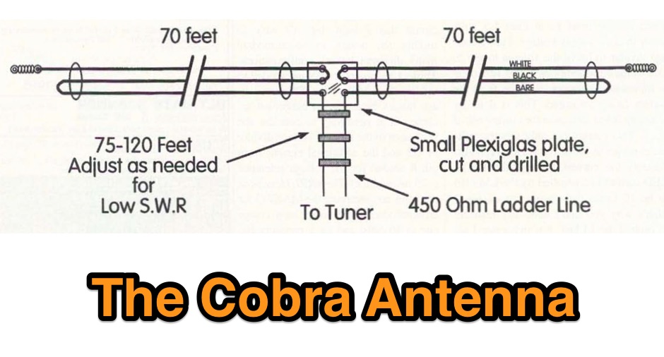 A folded wire antenna for 160 meters as appeared on 73 amateur radio magazine june 1997
 -
 Operational testing of a 10.07-meter portable HF vertical antenna, constructed from telescoping aluminum tubing (36, 32, 22, 17 mm diameters), yielded SWR measurements below 1.5 across multiple bands. Initial trials on 14.150 MHz showed an SWR of 1.6, while 7.075 MHz was problematic. Subsequent adjustments, including a 13 cm extension to the radiating element, improved performance, enabling operation on 6, 15, and 40 meters without a balun, and adding 12 meters with a balun. The design prioritizes portability, allowing transport in a standard vehicle and single-person deployment. Four 10.07-meter radials are connected at the base to enhance ground plane effectiveness. The article details the mechanical assembly, including custom adapters for tube transitions and a PVC sanitary tube sleeve for base insulation, ensuring robust field deployment. Final SWR measurements, documented with an _MFJ-259_ antenna analyzer, confirm operational ranges: 6.800-7.500 MHz (SWR < 1.5), 20.800-22.500 MHz (SWR < 1.5), and 48.800-51.500 MHz (SWR < 1.5) without a balun. With a balun, the antenna achieved SWR < 1.5 on 13.750-15.000 MHz and 24.890-28.350 MHz, demonstrating its versatility for portable _DXpeditions_.
 -
 Constructing an effective mobile antenna system for HF bands often presents challenges in achieving multi-band operation with a compact footprint. This project details the assembly of a versatile mobile antenna utilizing a standard _Hamstick_ base, enabling operation across 40, 20, 15, and 10 meters. The design incorporates a 102-inch whip and a custom-fabricated coil, allowing for quick band changes by adjusting the coil tap point. The document provides a parts list, step-by-step assembly instructions, and tuning considerations for optimizing SWR on each band. It emphasizes practical construction techniques for the coil and mounting hardware, ensuring mechanical integrity for mobile use. The antenna's performance is discussed in the context of typical mobile operating environments, highlighting its adaptability for various HF frequencies. Final adjustments involve precise trimming of the whip and coil taps to achieve resonance, with a focus on minimizing losses and maximizing radiation efficiency.
 -
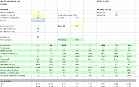 Excel spreadsheet that help calculating dimensions of a high efficiency magnetic loop antenna for HF bands. Giving in input the loop perimeter, loop diameter and loop conductor will calculate electric characteristics, bandwidth, and efficiency
 -

-
 A Low -Power, Distributed Capacitance Twisted Loop , indoor portable HF antenna by Monty Northrup, N5ESE
 -
 The PDF document, titled "J-Poles," presents various J-pole antenna designs covering the 50 MHz to 450 MHz frequency range. It includes construction details for several specific bands, such as a 6-meter J-pole, a 2-meter J-pole, and a 70-centimeter J-pole. The content outlines the fundamental principles of J-pole operation, including the quarter-wave radiator and half-wave matching stub. Each design features specific dimensions for elements like the radiator length, stub length, and spacing, often expressed in inches. The document also discusses feeding arrangements and impedance matching considerations inherent to J-pole antennas. It provides practical guidance for homebrewing these antennas using common materials like copper pipe or wire elements. The resource offers insights into the advantages of J-poles, such as their omnidirectional pattern and ease of construction, making it a practical reference for radio amateurs interested in VHF/UHF antenna projects.
 -
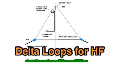 Planning and modelling Delta Loop antennas for all the ham radio HF bands include calculated wire lengths at each mid-band