Search results
Query: rf signal
Links: 330 | Categories: 10
Categories
- Technical Reference > RF Signal Generators
- Technical Reference > RF Design
- Technical Reference > Test Equipment > RF Probe
- Software > RF Coverage Mapping
- Technical Reference > Filters
- Radio Equipment > HF YAGI Antennas
- Antennas > Theory > Impedance matching
- Software > Oscilloscope
- Technical Reference > Receiver Front-End Protector
- Technical Reference > Test Equipment
-
 Learn about the practical design and construction of Yagi antennas for ham radio operators. This post explores the benefits of Yagi antennas in receiving and transmitting RF signals, concentrating signal energy in one direction for long-distance communication. Discover the theory behind Yagi antennae, the importance of element size and spacing, and the resources available for sizing and construction. Whether you're interested in OTA television or amateur radio communication, understanding Yagi antenna design can enhance your signal reception and transmission capabilities.
 -
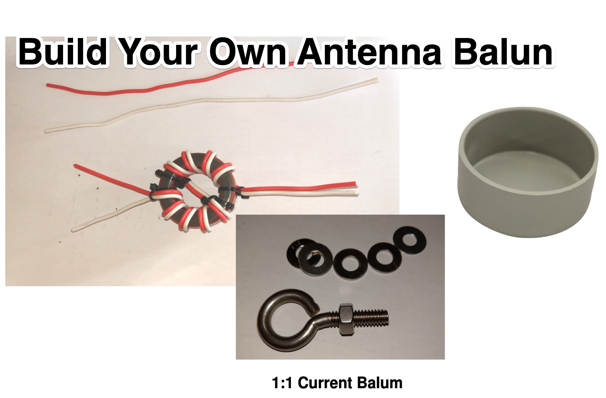 This PDF guide provides step-by-step instructions on how to build a Bunnings Balun for your ham radio antenna. A balun is essential for matching the impedance between your antenna and radio, improving signal transmission. The guide is perfect for hams looking to enhance their radio setup on a budget. Follow the detailed instructions to create your own balun using easily accessible materials from Bunnings or any hardware store.
 -
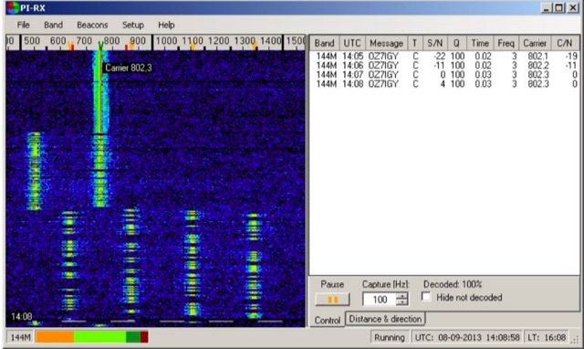 PI-RX is a beacon monitoring program capable of decoding PI4 and showing the performance of the decoded signal
 -
 This blog chronicles the development of an 80-meter vertical antenna for amateur radio operation. The author constructs a top-loaded vertical using fiberglass poles, achieving significant performance improvements over their previous end-fed wire antenna. Comparative testing using the Reverse Beacon Network and on-air contacts demonstrates 8-10 dB gain on the east coast. The project evolved to include 40-meter capability through a modified design featuring a four-wire vertical cage, loading coil, and strategic guying system. Despite challenges with signal wobble during windy conditions, the vertical consistently outperforms the end-fed wire, particularly for reaching distant stations during nighttime propagation.
 -
 The HF Beacon Tracker is an advanced interactive tool designed for DXers and ham radio opoerators in general to monitor active beacons operating below 14 MHz. Built upon a high-fidelity 3D Earth globe, the application provides a spatial perspective on signal paths by integrating real-time environmental data with a comprehensive beacon database curated by Mirek OK1DUB. Beacons are plotted using precise Maidenhead locators and feature a real-time day/night terminator overlay to help operators identify Gray Line propagation opportunities. With a single click, users can calculate the exact distance from their own QTH to any beacon, visualized via an animated Great-Circle Path arc on the globe surface. To enhance its diagnostic capabilities, the tool seamlessly integrates with PSK Reporter, allowing users to right-click CW beacons to instantly fetch current reception reports and signal strength data. The interface is fully optimized with a mobile-responsive design, smooth globe rotation, and togglable Dark/Light themes suitable for any shack environment. Whether you are performing antenna gain tests, conducting ionospheric research, or simply hunting for band openings, the HF Beacon Tracker transforms raw database information into an intuitive, visual diagnostic suite. It serves as an essential asset for any operator looking to master HF band conditions.
 -
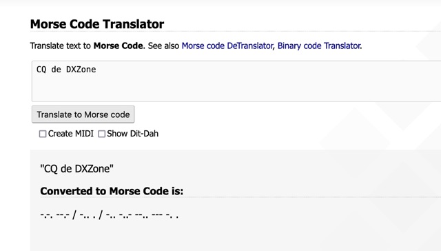 One primary function of this online utility is to convert plain text into _Morse code_, presenting the output in either a visual dit-dah sequence or as a downloadable MIDI file for auditory practice. The tool also provides the reverse capability, allowing operators to input Morse code and receive a decoded text translation. This bidirectional functionality supports both encoding messages for transmission practice and decoding received signals for improved copy. Operators can utilize the web interface for quick translations, making it accessible without software installation. The resource focuses on the fundamental aspects of CW communication, aiding in both learning and practical application of the code. Its design emphasizes simplicity and direct utility for amateur radio enthusiasts working with CW.
 -
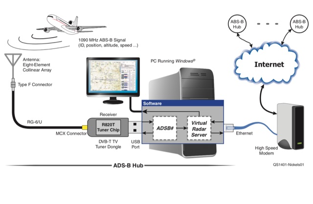 Track aircraft by reprogramming an inexpensive digital TV USB stick to receive Automatic Dependent Surveillance-Broadcast signals.
 -
 WB8LZR details the construction and initial field results of a multi-band vertical wire antenna, designed to complement his existing horizontal loop for improved DX on 80 meters. The antenna utilizes a 67-foot vertical wire, configured as a quarter-wave radiator on 80m, and employs a 1:1 current balun for RF isolation on 80m, 30m, and 17m. For bands like 40m, 20m, and 10m, where the wire acts as a half-wave or full-wave radiator, an additional impedance transforming _unun_ is integrated to manage the significantly higher feedpoint impedance and voltage. The author notes the vertical's performance as a receiving antenna, observing reduced noise compared to his main horizontal loop, particularly on 80m, and even hearing some long-path signals the loop missed. Initial QRP contacts, including a **1-watt** QSO with a _VP2 station_ on 30m, demonstrate its transmit capability. While the radial system is currently rudimentary, the project outlines practical considerations for multi-band vertical deployment and impedance matching.
 -
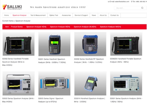 Saluki manufacturer of Spectrum Analyzer, Handheld Spectrum Analyzer, Signal Analyzer, Cable and antenna analyzer, Network Analyzer|RF Signal Generator, Cable Antenna Analyzer
 -
 This document provides a detailed guide on constructing and mounting a folded dipol for the 146 MHz frequency in a vertical configuration to be used in Yagi antennas. The step-by-step instructions and diagrams included make it easy for hams to build and set up this type of antenna. Understanding and implementing this design can enhance the performance of radio communication for Amateurs operating in the 2-meter band. Whether you are looking to improve your signal strength or experiment with antenna designs, this resource offers valuable insights and practical information.
 -
 This project focuses on testing and comparing various antennas for receiving ADS-B (Automatic Dependent Surveillance-Broadcast) signals, utilizing software tools like RTL1090 and Virtual Radar with an RTL-SDR dongle. The goal is to evaluate the reception range ("ReceiverRange") and performance of different antenna types when tracking aircraft signals, particularly around the Amersfoort area. The project includes a comprehensive photo album documenting the antenna designs and setup processes, serving as a valuable resource for enthusiasts building ADS-B reception systems
 -
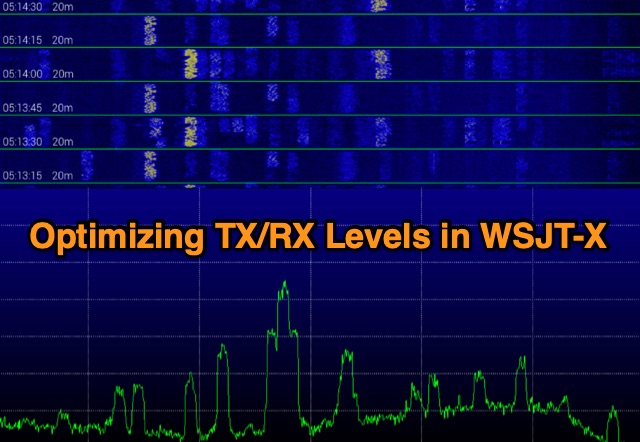 Exploring digital radio modes, the author rethinks how to adjust transmit and receive levels in WSJT-X. Despite effective communication using Yaesu's settings, a new procedure aims for better performance. For RX, set audio device levels to 100%, disable AGC, and adjust RF gain. For TX, enable "Remember power settings" and adjust power output to avoid ALC engagement. This method ensures reliable communication without signal degradation, enhancing dynamic range and minimizing noise.
 -
 The article describes the construction of a 1:49 impedance transformer designed to match the high impedance (around 2500Ω) of an end-fed half-wave (EFHW) dipole antenna to the 50Ω impedance of a typical transceiver. The EFHW is a popular portable antenna due to its simple construction, but feeding it can be challenging compared to a center-fed dipole. The transformer was built using an FT240-43 ferrite toroid core, with 2 primary and 14 secondary windings for a 1:49 impedance ratio. A capacitor was added in series with the primary winding to improve performance at higher frequencies. The author compared versions with one and two cores, and found that 100pF worked best for the single core design while 200pF was optimal for the dual core transformer.
 -
 The document details the construction and performance of a rotatable flag antenna designed for a small lot. The 7x14 feet flag, built with fiberglass poles and an aluminum hub, shows improved reception compared to the author's previous transmit antenna. Key components include a conventional transformer for impedance matching and a variable resistance termination system to optimize performance. Despite challenges like nearby objects affecting signal patterns, the antenna consistently provides better signal-to-noise ratios, making it a valuable addition for low-band listening in suburban areas.
 -
 This study details a reception comparison between vertical and horizontal active loop antennas, specifically two identical _Wellgood active loop antennas_, on various HF bands. The experiment, conducted in a densely populated QRM-prone area, monitored FT8 signals over a 24-hour period using two identical receivers. The methodology involved direct comparison of signal reception across the HF spectrum, aiming to identify performance differences based on antenna orientation. The results indicate that vertical loops demonstrated superior performance on higher bands (10m, 15m, 20m), while horizontal loops excelled on lower bands (30m, 40m, 160m), particularly for receiving long-distance (DX) signals. The horizontal loop's advantage on lower bands is attributed to potentially better low-angle performance and reduced sensitivity to man-made noise, yielding a **2-3 S-unit** improvement on 160m. The study provides practical insights for optimizing antenna placement in challenging urban environments, noting that the horizontal loop consistently showed a **10-15 dB** signal-to-noise ratio improvement on lower bands.
 -
 The 222 MHz Transverter project, based on Zack Lau's (W1VT) original July 1993 QEX magazine design, provides an IF of 28 MHz for both transmit and receive paths. Rick Bandla (VE3CVG) contributed supplemental notes and construction details, including modifications to achieve 10 mW output power from an initial 4 mW PEP. The design incorporates three distinct boards: a Local Oscillator (LO), a Transmitter (Tx), and a Receiver (Rx), with an estimated parts cost of just over $150 CDN, significantly less than commercial kits. Construction involves both through-hole and surface-mount components, with specific guidance on mounting MAV and MAR devices, grounding techniques, and component selection. The project details include parts lists, schematics for the LO, Tx, and Rx, and board layouts. Troubleshooting advice emphasizes sequential testing, starting with the LO, then Tx, and finally Rx, using a 194 MHz and 222.100 MHz capable FM handheld for signal tracing. Further enhancements are discussed, such as an optional Tx driver stage to boost output to 100 mW and the potential modification of a Motorola Maxor 80 PA for 222 MHz SSB/CW operation. The resource also covers practical aspects like power attenuation pads for IF radios (e.g., FT817) and considerations for enclosure design, including repurposing a Maxor 80 case. Performance reports indicate successful 70 km contacts with only 4 mW output.
 -
 This innovative antenna tuning unit (ATU) enables QRP operators to match their antennas without transmitting RF signals. Using a noise bridge technique instead of traditional transmit-and-tune methods, it achieves truly silent operation. The design incorporates an L-match network with switched inductors and variable capacitor, handling impedance matching from 3-30MHz. Operating from a 9V battery, it includes a built-in RF power meter and dummy load for QRP transmitter testing. The compact unit is particularly suitable for portable operations where minimal RF emissions during tuning are desired.
 -
 Ground Station offers real-time satellite tracking and radio communication capabilities, primarily for amateur radio operators engaged in satellite operations. It utilizes **TLE data** from sources like CelesTrak and SatNOGS for precise orbital prediction and integrates with various SDR devices, including RTL-SDR, SoapySDR, and UHD/USRP radios, to receive live signals. The software provides automated antenna rotator control and **Hamlib-compatible** rig control with Doppler correction, crucial for maintaining signal lock on fast-moving LEO satellites. It supports IQ recording in SigMF format and decodes several digital modes such as SSTV, FSK, GFSK, GMSK, and BPSK with AX25 USP Geoscan framing. Dedicated interfaces are available for satellite tracking, SDR waterfall displays with live transcription and packet decoding, and telemetry packet viewing. Users can manage TLE data synchronization and SDR hardware, along with browsing decoded outputs through an integrated file browser. An observations dashboard and DSP topology view further enhance the operational experience, providing comprehensive tools for monitoring and analyzing satellite passes.
 -
 This page provides detailed instructions on refining an end-fed vertical dipole antenna for ham radio operators looking to improve their signal reception and transmission. The content offers practical tips and techniques for optimizing the performance of this specific type of antenna. The page is useful for hams who are interested in experimenting with different antenna designs and configurations to enhance their overall radio communication experience.
 -
 The article details the design and construction of a four-band Moxon beam by a radio amateur. The beam, mounted atop a rooftop tower, aimed for gain over a dipole on 20 meters, cost under $500, and included additional bands. The design features fiberglass spreaders, four bands (20/15/10/6 meters), and a single feedpoint. The construction involved computer modeling, NEC source code, and specific dimensions. The article outlines the assembly, materials, and tuning process, including in-situ adjustments for optimal performance. Despite initial challenges, the beam improved signal strength and facilitated contacts on multiple bands, marking it as the best HF antenna the author has owned.
 -
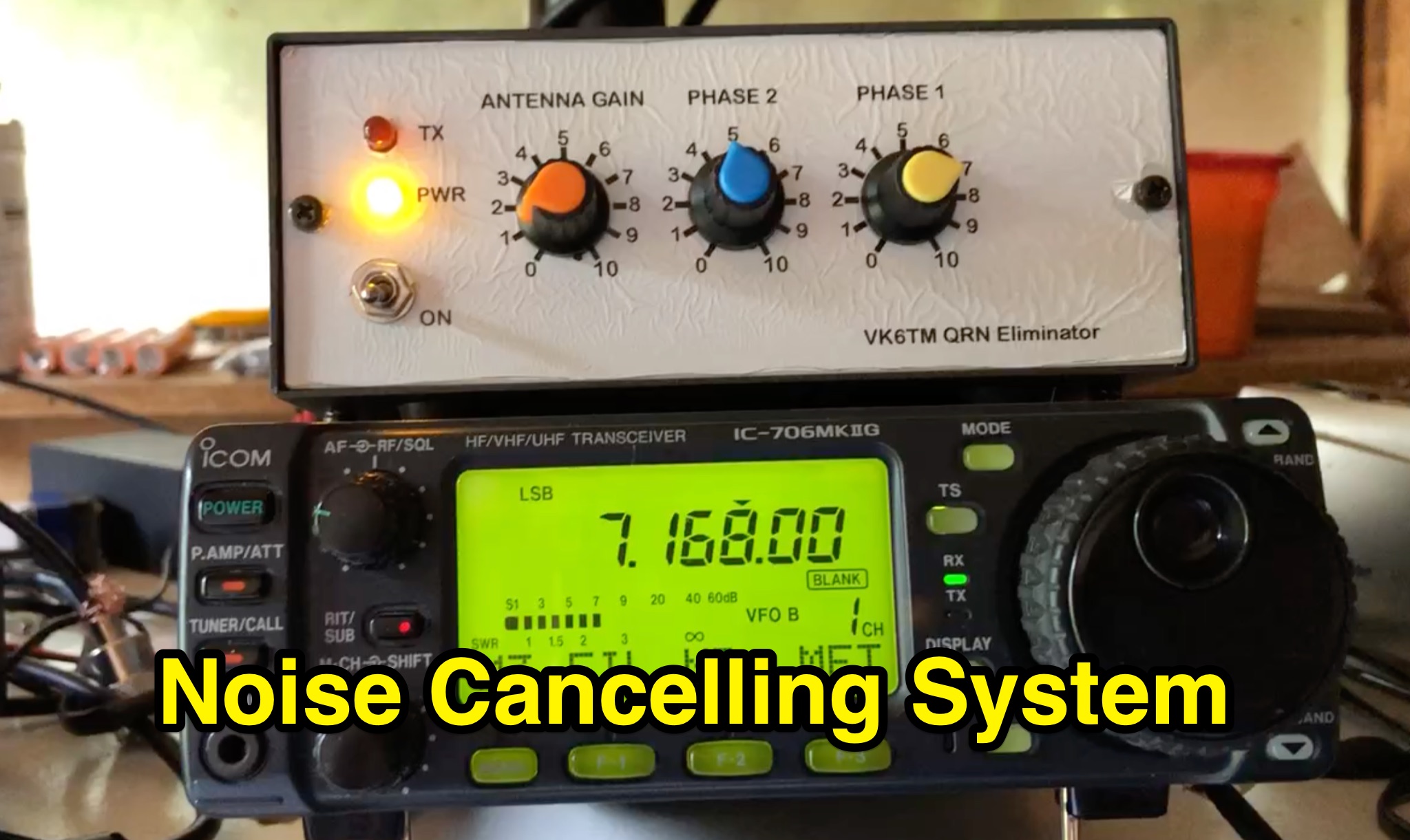 Learn how to improve reception on the hf bands by setting up a noise cancelling system that nulls out local interference. This article describes a system using a 'Main Station Antenna' to receive a wanted signal and associated QRM, and an 'Auxiliary Antenna' to pick up unwanted interference. Gain and phasing controls are used to reduce/remove interference, leaving only the wanted signal. Tips are provided based on the author's personal experience, applicable to commercial noise cancelling products, kit form, or homebrew setups. Discover the importance of configuring the 'Auxiliary Antenna' to optimize your system and improve readability of wanted stations.
 -
 A small magnetic loop antenna, often employed by hams facing antenna restrictions or high local RFI, offers a compact solution for HF operation. This resource details the construction of a foldable magnetic loop designed for the 40m through 17m bands, emphasizing its high-Q factor and _Faraday coupling_ for effective noise rejection and narrow-band filtering. The guide outlines material selection, advocating for copper over aluminum to maximize efficiency, and provides insights into the physics governing its operation, including impedance matching and resonance principles. Practical application of this antenna design is particularly beneficial for QRP enthusiasts and portable operators seeking a stealthy, high-performance antenna. The construction process includes specific details for a 1-meter diameter loop, a 140pF variable capacitor, and a _gamma match_ for impedance transformation. Performance comparisons suggest that while a full-size dipole might offer slightly better gain, the magnetic loop's ability to mitigate local noise often results in a superior signal-to-noise ratio, making it a viable option for challenging RF environments.
 -
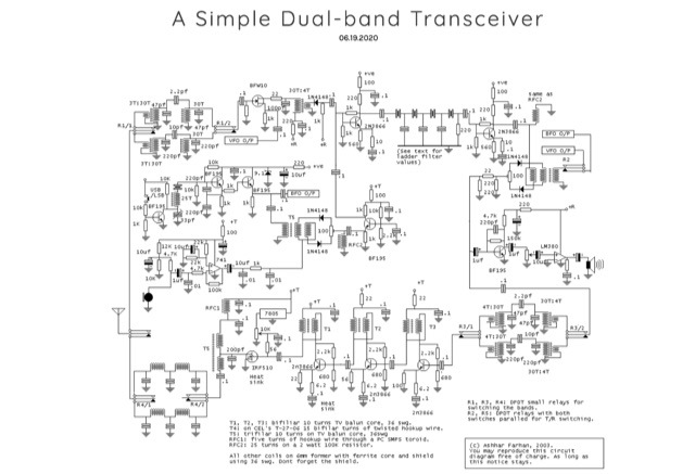 This a well performing, simple two band transceiver. The transceiver design is inspired by the S7C superhet. A dual-band transceiver with a crisp receiver and a clean SSB signal
 -
 Spotty leverages Philip Gladstone’s pskreporter.info data, delivered via an MQTT broker by Tom Fanning (M0LTE), to offer a responsive web application for visualizing propagation. The Map View presents a default visualization (grid AA00 / callsign MY8CALL) and distinguishes signal types: small spots for signals heard by a location, large spots for transmissions from a location, and teardrop markers for transmissions from the monitored callsign. Clicking a spot reveals detailed signal data in an overlay. The application includes a Log View for raw spot data and a Settings tab for customization. Users can filter tracking by specific Callsign or Grid, with preferences saved to the browser. A notable feature is the Time to Live (TTL) setting, adjustable from the default 60 seconds, which controls spot visibility duration to manage map clutter during high-traffic periods. The tool provides a clear, logic-driven interface for real-time signal monitoring.
 -
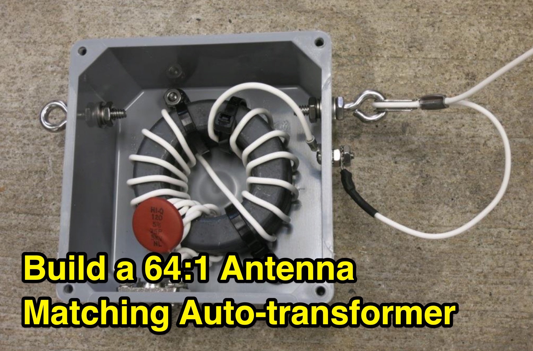 This PDF document provides information on a 64 to 1 antenna matching auto-transformer for ham radio operators. It likely includes details on how to build or use this specific type of antenna matching device, which can be helpful for hams looking to optimize their antenna setup. The document may contain technical specifications, diagrams, and instructions on how to properly implement the auto-transformer. Overall, it serves as a useful resource for hams interested in improving their antenna performance and signal transmission.
 -
 DecoAlert 1.0 Beta is a companion application designed to enhance the digital mode operating experience, specifically for FT8, FT4, and FT2. It operates by monitoring UDP data streams from primary decoding software like _Decodium_ and _WSJT-X_ on port 2237. The software provides real-time, priority-based audio alerts using WAV sounds for various conditions, including All Time New Ones (ATNO), new DXCC entities per band/mode, user-defined watchlist callsigns, new Maidenhead grid squares, and LoTW-active stations. It also highlights previously worked stations (B4) and integrates live DX spots from Telnet clusters, offering a comprehensive suite of tools for serious digital mode operators. The application features a built-in SQLite database for tracking worked stations and integrates with LoTW user lists to identify confirmed contacts. A DX Cluster client supports multiple Telnet servers, providing a broad view of propagation. PSKReporter statistics are available by band and mode, offering insights into signal paths. The QSO log viewer includes search and filter capabilities, while an _OpenStreetMap_ (OSM) interface visualizes spot locations, aiding in situational awareness. DecoAlert requires Windows 10/11 (64-bit) and compatible digital mode software configured to send UDP data.
 -
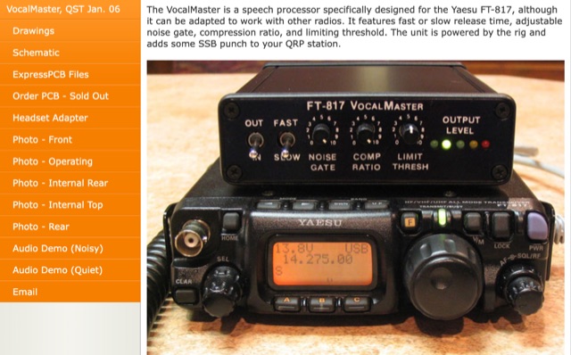
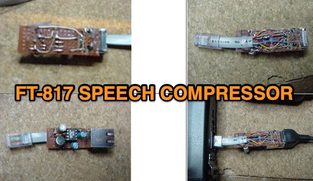 Designed for the FT-817, this audio speech compressor, centered on the Analog Devices SSM2165, offers a 40 dB compression range, enhancing signal power. Built externally with the SMD version to preserve warranty, the circuit interfaces smoothly with electret microphones. Testing shows a 6 dB average power increase. Adaptable to rigs with electret microphones, it maintains unity gain and 40 dB compression.
 -
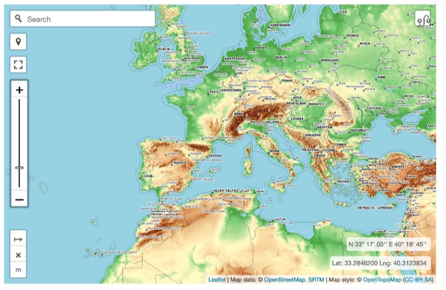 Online interactive elevationmap can help radio amateurs by predicting signal propagation, optimizing antenna placement, planning coverage, ensuring line-of-sight, mitigating interference, and enhancing emergency communication. T
 -
 This project describes the construction of a W3HH (T2FD) antenna for HF bands (3-30 MHz). While less efficient than a tuned dipole, it offers broad frequency coverage with a maximum SWR of 3.4 and reduces QRM (noise) significantly. On the 80-meter band, it shows slightly weaker signals than a dipole but with improved signal-to-noise ratio. The design includes non-inductive resistors, a 13:1 balun, and a "frog ladder" transmission line. Though not a high-performance antenna, it is compact and versatile, making it ideal for wide-band HF communication. Article in French
 -
 PH0NO conducted field tests comparing a mobile antenna (DX-UHV) to an end-fed half-wave wire. Results on 20m showed the end-fed wire outperforming the mobile antenna, with a significant difference in signal strength. On 40m, the end-fed wire surpassed the mobile antenna in spots and reach. While the mobile antenna is more practical, the end-fed wire offers superior performance. Further testing is planned.
 -
 Inspired by Heathkit, author aimed to enhance his Yaesu FT-817 with audio and RF processing. Design goals included a compact enclosure, PCB simplicity, matching jacks, a visual meter, and a built-in signal generator. Despite challenges in finding a suitable compressor IC for a 5V DC mic jack, he chose the Analog Devices SSM2165/2166 series. Prototyping with a solderless breadboard, author planned a PCB layout for its versatile performance in communication use.
 -
 Chokes and isolation transformers are essential for receiving antennas to mitigate common mode current, which induces noise and interferes with signal quality. Common mode chokes, formed by winding feedline through ferrite cores, block unwanted current effectively. Proper selection of core material and winding turns ensures resonance near the operating frequency, reducing interference. Isolation transformers further minimize interference, crucial for multi-transmitter stations.
 -
 This article focus on the radiation angle of vertical antennas and the fundamentals of electromagnetic wave propagation. The calculation of antenna length at 145 MHz is followed by an explanation of electromagnetic wave speed and the link between wavelength, frequency, and velocity. Author discusses the 5/8th wave vertical antenna, namely its performance and the influence of radiation angle on signal transmission. Figures and analogies demonstrate how different antenna types produce distinct radiation patterns. This highlights the importance of selecting the right antenna for a certain purpose, such as local traffic or dxing. The article discusses a variety of factors that affect antenna performance, including SWR, propagation conditions, and equipment dependability
 -
 Demonstrates the construction and portable deployment of a 40-meter horizontal loop antenna, often referred to as a "Sky Loop" or "DX-Buster." The design adapts a full-wavelength horizontal loop for field use, eliminating the need for traditional insulators by employing four 5-meter heavy-duty _squid poles_ and metal post bases for support. This setup facilitates rapid assembly, crucial for portable operations, with the antenna wire length specified at approximately 43-45 meters for optimal 40-meter band performance. The resource details the specific construction methodology, including winding the antenna wire around rubber caps on the squid poles and securing it with electrical tape. It provides a parts list and assembly techniques, focusing on minimizing components for ease of transport and quick setup. The article, originally published in the February 2013 edition of the Central Coast ARC "Smoke Signals" magazine, reflects practical experience. This documentation offers a field-deployable 40-meter loop antenna solution, utilizing readily available components like fiberglass squid poles. It presents a practical approach for operators seeking a robust, portable antenna for the 40-meter band, emphasizing simplicity and efficiency in its design and deployment.
 -
 This document provides comprehensive guidance on modeling and constructing multiband dipole antennas using traps. It addresses common segmentation issues in EZNEC modeling software, recommends optimal segment lengths for trap models, and compares trapped dipoles with paralleled multiband dipoles. While trap dipoles are significantly shorter, they exhibit lower gain and narrower bandwidth. Detailed instructions for building weatherproof coaxial traps include material lists, construction steps, and tuning methods. The guide notes that properly constructed coaxial traps introduce only minimal signal loss (0.6 dB) while offering practical multiband performance in a compact design.
 -
 Chavdar Levkov, LZ1AQ, presents an experimental comparison of small wideband magnetic loops, building on his previous work on wideband active small magnetic loop antennas. His research focuses on increasing loop sensitivity by maximizing the short-circuit current, which is directly tied to the "loop factor" M = A/L, where A is the equivalent loop area and L is its inductance. Levkov's methodology involves reducing inductance and increasing area through parallel or coplanar crossed (CC) configurations, comparing these designs against a reference single quad loop of 1 m2 area. Experimental verification included testing three distinct loop types: a simple quad loop, two coplanar crossed (CC) loops, and eight parallel loops, all designed to have a total geometric area of 1 m2. Measurements were conducted at 1.8, 3.5, 7, and 10 MHz using a small transmitter 270 meters away, with a Perseus direct sampling receiver for precise signal level assessment. The results consistently showed that CC loops, particularly Loop 5 (two CC circular loops with 1.44 m2 total area), yielded significantly higher currents, up to 9.1 dB over the reference loop at 3.5 MHz, validating M as a reliable predictor of loop sensitivity. Numerical simulations using MMANA further corroborated the experimental findings, demonstrating an almost perfect correlation between the calculated M factor and the induced loop current for 15 different loop models. Levkov concludes that CC loops offer superior sensitivity for a given loop area, while parallel loops are advantageous for minimizing physical volume. Practical recommendations suggest using loops with an M factor greater than 0.5 uA/pT for quiet rural environments, and he provides a spreadsheet tool, WLoop_calc.xls, to aid in optimizing loop configurations for specific operational needs.
 -
 In his POTA activation, WK4DS experimented with radials for hamstick antennas. Despite sun and RF noise challenges, successful connections were made. Surprisingly, tuned radials proved unnecessary, simplifying setup. Hamsticks demonstrated versatility across frequencies. Increased power improved signal quality, sparking his curiosity for further exploration in radio technology.
 -
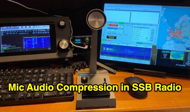 Single-sideband (SSB) radio enhances spectral efficiency but poses challenges with audio intelligibility, particularly in noisy conditions. A microphone audio compressor addresses these issues by dynamically managing the audio signal’s dynamic range. It amplifies quiet sounds and attenuates loud ones, ensuring consistent audio levels for improved clarity. Benefits include increased intelligibility, higher average power, and reduced spurious emissions. While essential for optimal SSB performance, careful parameter adjustment is crucial to balance natural sound quality and effective communication across various operating modes.
 -
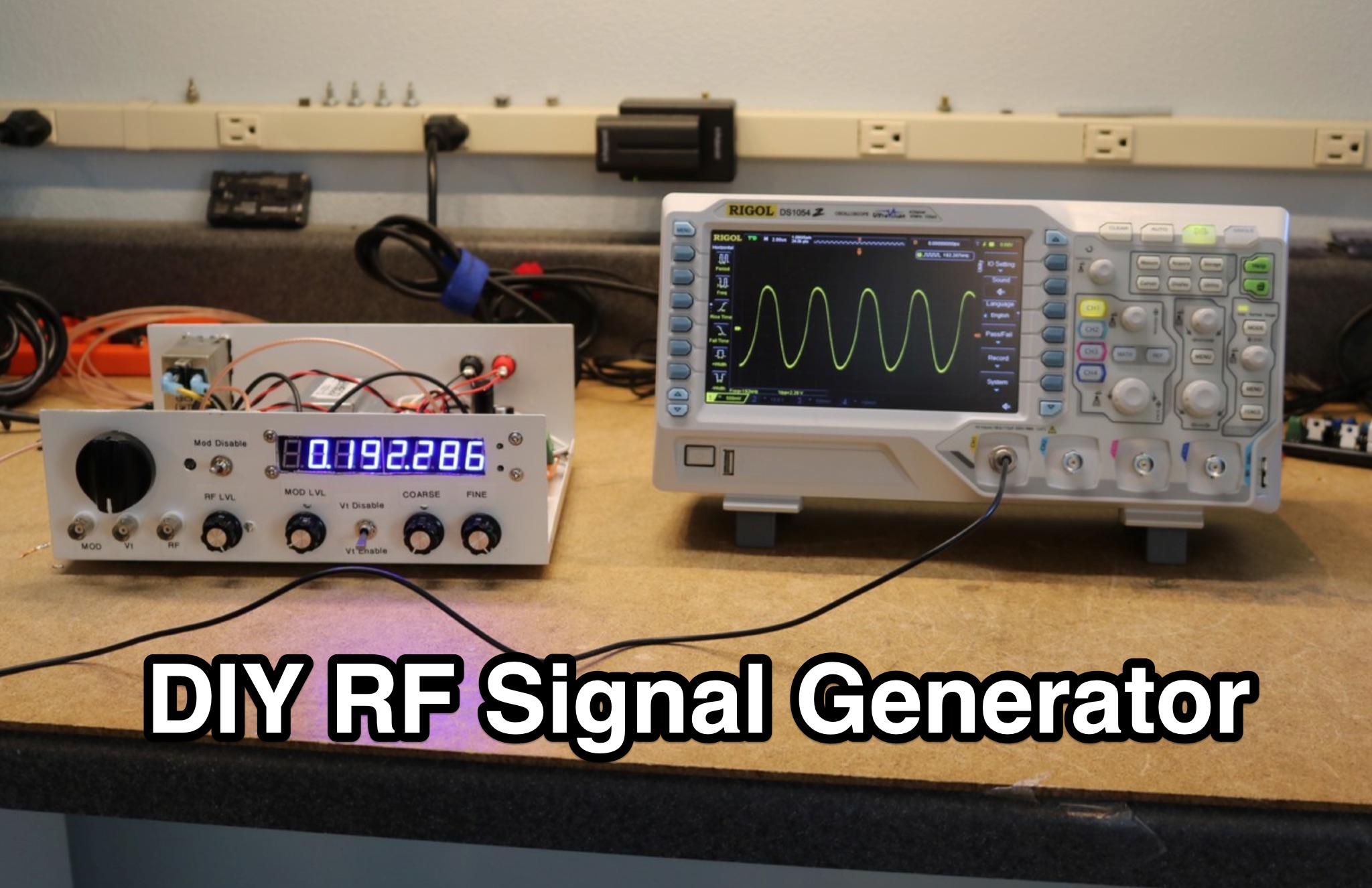 Learn how to build your own RF signal generator for aligning radios by following the modifications made to the circuit of an existing project. Explore the use of a common cathode varactor diode and a single center-tapped 24 VAC transformer to simplify the design. Discover alternative components like the MACOM 4ST079CK-287T varactor diode, which offers cost-effective solutions compared to unobtainable options. Find inspiration in modifying existing projects and gaining practical knowledge in electronics. Purchase the Nuts and Volts magazine for detailed schematics and a deeper understanding of RF signal generators.
 -
 Effective suppression of harmonics and parasitic radiation from HF transmitters is crucial, especially with the increasing sensitivity of VHF/UHF radio channels to interference. This project details a hybrid low-pass filter (LPF) designed to operate across the HF bands up to 51 MHz, making it suitable for 6-meter band operations while providing deep VHF/UHF suppression. The design addresses the challenge of modern interference landscapes, where even microvolt-level signals can disrupt wireless sensors and other simple VHF/UHF receivers. The filter utilizes a single elliptic link, combining high cutoff steepness with robust suppression in the hundreds of megahertz range. A key feature is the use of only two standard capacitor values, simplifying construction and component sourcing. The article provides a detailed schematic, performance characteristics, and _RFSim99_ model file, demonstrating a reflection coefficient S11 below 0.017 (VSWR < 1.03) across 1-51 MHz, ensuring minimal degradation to the antenna system. Construction notes include coil winding specifications and capacitor selection guidance, with recommendations for _FR-4_ assembly. Two capacitor sets are presented, with the first variant recommended for its lower RF current demands, keeping currents below 3 A at 1 kW passing power at 51 MHz. Fine-tuning involves adjusting frameless coils, with considerations for capacitor tolerance and high-frequency capacitance measurement accuracy.
 -
 Compare the efficiency of two HF (or VHF) antennas by simultaneously transmitting FT8 on nearly the same frequency and analyzing PSKReporter SNR data. Determine the effectiveness of your new antenna compared to the old one in dB, to several decimal places. Run FT8 on two transmitters with different call signs and equal power, connected to each antenna. AntennaCompare analyzes global signal reports, isolating antenna performance.
 -
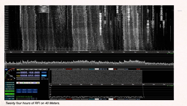 Demonstrates the application of Software-Defined Radios (SDRs) as effective tools for conducting Radio Frequency Interference (RFI) site surveys. The resource details the methodology for capturing and analyzing RFI, specifically focusing on the 80-meter band over a 24-hour period. It outlines the setup of an SDR-based survey tool, utilizing software like _S-Meter Lite_ and _Spectrum Lab_ to visualize and quantify noise sources. The article emphasizes the SDR's wideband capabilities, which allow for comprehensive identification and documentation of RFI across broad frequency ranges, crucial for effective mitigation strategies. The analysis presents practical results, illustrating how continuous monitoring can reveal intermittent RFI sources that might otherwise go undetected. For instance, the survey identified noise peaks exceeding **S9+20dB** on 80 meters during specific hours, correlating with local appliance usage. The methodology provides a repeatable process for hams to characterize their local noise floor, enabling targeted RFI suppression efforts and improving weak-signal reception, particularly for DXing and contesting.
 -
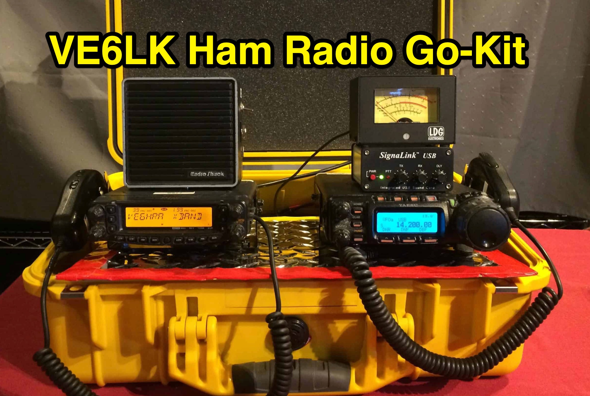 Learn how VE6LK built a comprehensive radio go-kit for emergency communication purposes. The kit includes Yaesu FT-8800, Yaesu FT-857, LDG FT-Meter, Powerwerx SS-30 power supply, SignaLink USB interface, and more. The author shares details on the equipment, organization, and practical tips for setting up the kit. Discover how to stay prepared for public service events, disaster responses, and general ham radio activities with a well-equipped go-kit.
 -
 This project details the development of a modular direct conversion (DC) receiver designed for experimental flexibility in amateur radio and HF signal listening. The mainframe integrates a diplexer, DBM, and AF amplifier, supporting interchangeable local oscillator and antenna filtering setups. A tunable passive HF preselector complements QRP Labs bandpass filters for enhanced signal reception. Utilizing a NanoVNA for precise tuning, the receiver achieves improved signal-to-noise ratios across amateur and non-amateur bands, making it a versatile platform for further RF experimentation.
 -
 Learn how to enhance your 160 meter reception by building and using a custom band pass filter. Discover how this filter can reduce interference from strong AM broadcast signals, improving the overall performance of your receiver. Find out about the challenges of creating a filter that balances signal loss and attenuation at specific frequencies, and how it can benefit hams operating near powerful transmitters. Whether you're experiencing IMD issues or looking to optimize your 160 meter setup, this article provides practical insights and solutions for ham radio operators.
 -
 Integrating a _Software Defined Radio_ (SDR) into an existing ham radio setup involves connecting it with a standard transceiver (TRX), power amplifier (PA), and antennas. The core component is a splitter box that facilitates the connection between the TRX and the SDR, allowing for simultaneous operation without modifying existing equipment. In receive mode, the splitter ties the antenna inputs of both the TRX and a direct conversion receiver (DC RX) together. During transmission, the DC RX input is grounded via a fast telecom relay controlled by the transceiver's -SEND signal, incorporating a 10ms delay for safety. The splitter box includes a 3.7 dB input attenuator for impedance matching and acts as a protective fuse for the DC RX input. Ground loops are mitigated using common mode balun transformers, while the DC RX input is insulated with a broadband transformer. An audio switch box complements the setup, enabling users to listen to either the main transceiver, the SDR output, or both simultaneously. This configuration ensures noise immunity and safety, with the splitter housed in a screened box made from PCB material. On-air tests, such as the CQ WW 160m CW DX Contest, demonstrate the system's effectiveness, showcasing the SDR's ability to handle crowded band conditions with superior selectivity and dynamic range. The SDR's narrow bandwidth filters and waterfall display provide significant advantages, allowing operators to detect weak signals amidst strong interference. The integration of SDR with conventional radios offers enhanced operational flexibility and performance in challenging environments.
 -
 The Acom 1500 HF+6M Linear Amplifier is a high-quality and user-friendly amplifier that provides excellent performance and reliability. G6NHU, who previously owned an Acom 1000, upgraded to the Acom 1500 after nine years and has been using it for about eighteen months. Key features highlighted include the ability to connect three antennas internally, straightforward tuning process, robust construction that can handle high SWR, quiet operation, fast and quiet switching for efficient CW operation, and clean output signal even when driven hard. G6NHU highly recommends the Acom 1500 and states they would not hesitate to purchase another one in the future.
 -
 The article discusses the evolution of antenna designs, specifically focusing on the upgrade from the W7IUV rotatable Flag to the Waller Flag. Author Pierluigi Mansutti IV3PRK shares insights on modeling these antennas using EZNEC software, detailing their performance in noisy environments. The W7IUV Flag proved effective for receiving signals, while the Waller Flag, developed by NX4D and N4IS, offers improved front-to-back ratios but requires careful consideration of signal levels and noise management. The article emphasizes practical modeling results and interactions between different antenna setups.
 -
 An FT-817 ceased transmission on the VHF 2m band, despite the other HF, UHF, and 50 MHz bands operating correctly. Suspecting an excess of input signal during FT-8 mode transmission, they conducted measurements with an oscilloscope, revealing a burnt-out PIN diode, identified as D3003, type HSU277, on the PA unit board. Following the replacement of this surface-mounted diode, their FT-817 resumed operation on the 144 MHz band.
 -
 This project involved designing a 7-pole Chebychev broadcast band filter to address severe interference issues caused by a new horizontal loop antenna on the KN-Q7A transceiver. The interference overwhelmed the transceiver’s front end, so a custom filter with a 3.5 MHz cutoff was built using silver mica capacitors and type 6 T130 toroidal cores. Encased in a diecast box with SO239 sockets, the filter blocks strong signals from the broadcast band, achieving over 100 dB attenuation. Tested up to 100W, it reduces interference effectively while maintaining low insertion loss across HF bands.