Search results
Query: eme antenna
Links: 878 | Categories: 9
Categories
- Antennas > 6M > 6 meter Yagi Antennas
- Antennas > Antenna Books
- Software > EME
- Radio Equipment > HF YAGI Antennas > Hy-Gain TH3JR
- Technical Reference > Lightning Protection
- Operating Modes > WiFi > Long Range WiFi
- Antennas > Maria Maluca
- Antennas > Feed Lines > Open Wire
- Technical Reference > Standing Wave Ratio
-
 Anyone attempting to work DX on Top-Band 160 Meters, soon learns of the need for a good receiving antenna. This is a 160 meter 8 element receiving array.
 -
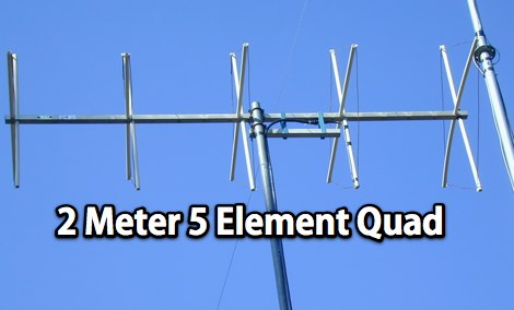 A five element quad antenna for 144 MHz DIY Project. This 2 Meter 5 Element Quad antenna was modeled using EZNEC, with a boom from a UHF TV antenna and CPVC pipe for spreaders. Constructed for 146MHz, it exhibits a gain of 10.7dB and an impedance of 75 ohms. Real-world results surpass the HT antenna, reaching over 20 repeaters up to 75 miles away. The design, costing around $10, employs simple tools for assembly.
 -
 In these slides, differences between spiderbeam antenna and hexbeam antennas are explained comparing performances and measurements.
 -
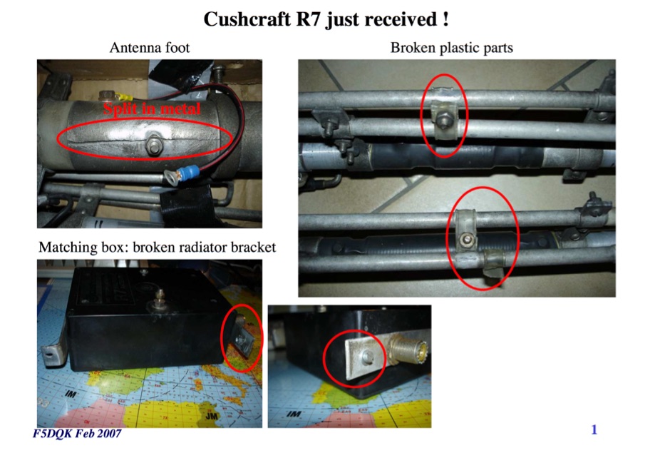 F5DQK repairing and swr measurement tests of a Cushcraft R7 Antenna
 -
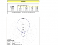
-
 The **70cm Moxon Beam** project outlines the construction and testing of a compact, directional antenna for the 432 MHz band. G3XBM recounts his early 1980s experience with a 4W FM321 transceiver and a Jaybeam 48-element TV antenna, which provided a baseline for his later UHF antenna experiments. This project focuses on a simpler, yet effective, design for local and regional contacts, emphasizing ease of construction and practical field results over complex theory. The article details the specific dimensions and materials used for the Moxon rectangle, including 6mm diameter aluminum tubing for the elements and a PVC boom. G3XBM notes that the antenna was built for portable use, making it lightweight and easily deployable for field operations. The feedpoint impedance was measured at 50 ohms, ensuring a direct match without the need for an external tuner, which simplifies setup. Performance tests included comparisons against a commercial 5-element Yagi, revealing that the Moxon provided comparable forward gain and an excellent front-to-back ratio, crucial for reducing local QRM. The author's observations confirm the Moxon's reputation as a robust performer for its size, suitable for both fixed and portable 70cm operations.
 -
 A GSM1800 Moxon Square antenna project is presented, detailing its construction using three 1.5mm copper wire pieces for the reflector and dipole elements. The design inherently offers a 50-ohm feedpoint impedance, allowing direct connection to 50-ohm coax without complex matching networks like baluns or gamma matches, which are prone to high attenuation at 1.8 GHz if not precisely built. The resource includes a construction plan, expected **SWR plots**, and **radiation patterns** for the GSM 1800 band, specifically covering the 1710-1785 MHz transmit (red zone) and 1805-1880 MHz receive (blue zone) segments. The SWR remains below 2:1 across the entire GSM 1800 band, with the main lobe consistently achieving 5-6 dBi gain. While the radiation pattern shows some changes across the band, these primarily affect the back of the antenna, maintaining consistent forward gain. Practical considerations for high-frequency operation are emphasized, such as minimizing coax length (e.g., under 1 meter for RG-174) and selecting appropriate connectors like N, SMA, or BNC to mitigate significant attenuation. The article also discusses direct connection to the phone's RF PCB for minimal loss and notes observed signal strength variations with antenna orientation despite crossed polarization at cell sites.
 -
 A Moxon rectangle antenna design for the 11-meter band is presented, offering a compact and lightweight solution for directional HF DX operation. This two-element parasitic array, popular among amateur radio enthusiasts, provides considerable directional gain and lower noise on horizontal polarization. The design is suitable for both 27 MHz Citizens Band (CB) and the lower portion of the 28 MHz amateur radio band, making it versatile for operators interested in either service. Construction can utilize materials like bamboo, squid poles with wire elements, or aluminum tubing on a central boom. The article includes a plan view diagram with specific dimensions (A-E) in centimeters and inches for building the antenna, such as a 392.09 cm (154 3/8 inch) driven element. The Moxon configuration inherently presents a 50 Ohm load to the transceiver, often eliminating the need for an external matching unit or balun. Performance data for an antenna mounted at approximately 30 feet indicates a gain of 10-11 dBi and a frequency range of 27.300 MHz to 28.300 MHz. The design is noted for its excellent front-to-back rejection, with tested signal drop-offs from S5-S7 to S2 when turned, demonstrating effective suppression of unwanted signals.
 -
 Slot antenna and complementary dipole
 -
 This article describes the 144MHz horizontally polarised antenna at VK1OD in November 2008. The antenna uses two identical four element arrays that were constructed around 1970
 -
 Demonstrates the product line of _LZ Antenna Ltd._, a Bulgarian manufacturer specializing in amateur radio antennas and custom electronic devices. The company focuses on robust, high-quality HF multiband Yagi and vertical antennas, leveraging over 20 years of experience from founder Georgi Georgiev in radio amateur development. Featured models include the LZA 8-4, LZA-10-3, and the LZA-7-3A WRTC 2022, alongside various rotary dipoles like the LZA1 40/30m. Provides specifications for several Yagi antennas, such as the LZA-9-5, LZA-13-7, and LZA-6-3 (a 6-element, 3-band design). The company emphasizes applying "leading edge technology" to high-frequency communication equipment production, with products designed for durability and performance. The LZA-10-5 Yagi offers **12.5 dBi** gain on 10m, while the LZA-13-7 provides **13.2 dBi** on 20m, showcasing competitive gain figures for DXing and contesting.
 -
 An antenna originally planned in the sixties, a two element beam antenna tunable on several band, in french
 -
 Presents a construction project for a linear-loaded 40-meter rotatable dipole, detailing the design evolution from mid-element coils to 300-ohm twinlead loading. It covers material selection, including repurposed fishing poles and EMT conduit, and outlines the assembly process for the antenna elements and mounting plate. The resource provides specific measurements for element lengths and linear loading sections, along with SWR plots demonstrating the antenna's resonance at 7.035 MHz with a 1.1:1 SWR, and bandwidth up to 7.120 MHz below 2:1 SWR. The article documents the antenna's performance during various RTTY and CW contests, including the SARTG RTTY and SCC RTTY contests in August 2006, and the ARRL DX CW and CQWW WPX RTTY contests in February 2007. It reports successful operation at 500-1000W, noting improved performance after replacing a faulty coax cable. Specific DX contacts from British Columbia, including stations in Europe and South Africa, are listed, illustrating the antenna's capability despite its shortened length and relatively low height of 55 feet. The content highlights practical considerations such as weatherproofing the connections and supporting the fiberglass elements to prevent sagging. It also includes a brief comparison to an inverted-V at similar height and a ground-mounted vertical, noting the rotatable dipole's quieter reception. The author shares insights into the iterative design process and tuning adjustments made to achieve optimal resonance.
 -
 Constructing a portable, high-gain antenna for _AO-40_ satellite operations presents unique challenges, particularly regarding mechanical stability and parabolic accuracy. This resource details the build of a 1.2-meter "brolly dish" antenna, utilizing a non-conducting fiberglass umbrella frame as its foundation. The project outlines a method for achieving a parabolic shape using stressed aluminum fly screen mesh, guided by practical geometry and a temporary dowel template. Key steps include selecting an appropriate umbrella with a suitable f/D ratio (ideally >0.25), removing the original fabric, and precisely cutting and attaching eight segments of fly screen to the struts to form the reflective surface. The construction process, which took approximately five hours for the author, _G6LVB_, resulted in a dish with an f/D of 0.27 (depth=270mm, diameter=1160mm, f=310mm). The article also describes a modification to a _TransSystem AIDC_ feed, incorporating a PCB reflector behind the dipole for easier mounting. Performance tests at a squint angle of 15 deg and a range of 50,000km yielded a signal-to-noise ratio of 33dB on the S2 beacon and 23dB for SSB signals, indicating strong reception. The author notes that the modified umbrella may not close fully without risking surface disfigurement.
 -
 Various publications through the years have shown how the SWR measured on a shorted (or open) feed line can be used to calculate feed line attenuation
 -
 A 20-meter vertical _Moxon_ antenna, designed for portable operation, is detailed with specific dimensions for its driven and reflector elements. The project outlines the construction process, including the use of PVC pipe for the frame and #14 AWG insulated wire for the elements. The antenna's compact size and directional characteristics make it suitable for field day operations or limited space environments, offering a gain of approximately 5.5 dBi and a front-to-back ratio of 20 dB. Testing revealed a 1.2:1 SWR at 14.250 MHz, demonstrating good impedance matching across the target frequency range. The _Moxon rectangle_ design provides a clean radiation pattern with minimal side lobes, which is advantageous for reducing QRM from unwanted directions. This build offers a practical solution for hams seeking a lightweight, easily deployable directional antenna for 20 meters without the complexity of a full-sized Yagi.
 -
 Investigates the gain characteristics of the **axial-mode helix antenna**, a widely used circularly-polarized antenna, by addressing conflicting claims in amateur literature regarding its performance. This article summarizes an extensive numerical modeling study using **NEC-2** to simulate approximately 10,000 different helical antenna configurations, systematically varying physical parameters like length and turn radius. The study consumed around 3,000 hours of compute cycles, with each antenna model utilizing between 600 and 1,400 segments for accuracy. The modeling data were rigorously compared against professional antenna literature, including experimental and theoretical work, revealing that the original Kraus formula for gain is often overly optimistic, predicting gains up to 4 or 5 dB higher than observed. Empirical expressions are provided for the maximum possible gain, Gmax(dB) = 10.25 + 1.22 L - 0.0726 L^2, and the optimum turn radius, Rmax = 0.2025 - 0.0079 L + 0.000515 L^2, both valid for antenna lengths (L) between 2 and 7 wavelengths. The research also notes that a half-lambda square groundplane performs nearly as well as an infinite groundplane, while radials incur a gain penalty of about 3.5 dB.
 -
-
 Review by G3TXQ and comparison to its modificated versions. SWR Measurements on inverted V setup and comparison from EZNEC model and a real one.
 -

-
 About beverage antennas, Enhanced F/B Beverages, Bandwidth of Directivity, arrays. This article describes two phasing systems for Beverage antennas that improve directivity and cancel rearward signals. These systems use lossy elements and require minimal components to achieve broadband performance.
 -
 Presents the design and performance of a 4-element wire Yagi antenna for the 40-meter band, building upon VE3VN's earlier 3-element switchable wire Yagi. The resource details the antenna's evolution, highlighting the transition from a 3-element to a 4-element configuration and the resulting improvements in gain and front-to-back ratio. It provides specific insights into the antenna's construction and expected operational characteristics. VE3VN shares insights from field results, noting the antenna's performance on 40 meters. The discussion includes the antenna's pattern and matching characteristics, crucial for any DXer or contester looking to optimize their signal on this popular HF band. The author's experience with the previous 3-element design informs the enhancements made to this 4-element iteration. The article includes a visual representation of the antenna's current view, offering a practical perspective on its physical layout. It serves as a valuable reference for hams considering a directional wire antenna for 7 MHz operations, demonstrating a practical approach to achieving enhanced directivity and gain.
 -
 The resource details the construction of a 6-meter _Moxon_ antenna, presenting two distinct versions: one horizontally polarized for 50-51 MHz CW/SSB and another vertically polarized for 52-54 MHz FM. It specifies the use of 5/8 inch OD and 1/2 inch OD aluminum tubing, with 3/8 inch OD solid aluminum for corners, and provides a comprehensive material cutting schedule. The design aims for robust, portable construction, with all materials costing under $100. Detailed drawings and EZNEC models are referenced for precise dimensions and assembly, ensuring accurate element spacing and impedance matching. The EZNEC model for the H-POL version predicts a gain of **11 dBi** and a front-to-back ratio of **25 dB** at 50.5 MHz, while the V-POL version shows a gain of **6.7 dBi** and a front-to-back ratio of **36 dB** at 53 MHz. The article includes practical SWR measurement advice, noting the impact of coax length and loss on analyzer readings. Field tests during a tropical storm demonstrated the antenna's durability and performance, yielding numerous contacts across significant distances, including California, Colorado, and Texas, on SSB and PSK.
 -
 Demonstrates the design and construction of a compact, portable multi-band mini-delta loop antenna, specifically optimized for /P (portable) operations from remote locations like Scottish islands. The resource covers the theoretical underpinnings of half-wave loops, contrasting closed and open configurations, and then details the application of a folded dipole principle to achieve a 50-ohm match for direct coax feed. It presents empirical formulas for calculating element lengths, considering the velocity factor of common wire types, and provides a detailed example for a 20m (14.175 MHz) version. The article includes a comprehensive table of dimensions and allowances for a five-band (20m, 17m, 15m, 12m, 10m) mini-delta beam, along with construction hints for the central support and balun. It specifies a 1:1 trifilar balun wound on a ferrite rod and describes the antenna adjustment process using an _MFJ-259B Antenna Analyser_. Initial test results indicate an SWR of 1:1 at resonance and a bandwidth of approximately 240 kHz on 20m, even at a low height of five feet above ground. The distinctive utility lies in its focus on a practical, easily deployable beam antenna for portable DXing, offering a viable alternative to more complex or larger arrays.
 -
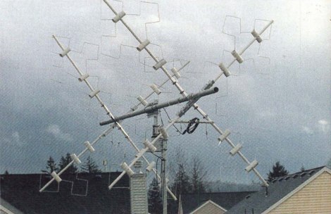 Presents the construction of a 10-meter Fractal Quad Yagi (FQY) antenna, detailing the design principles and practical build steps. The article highlights the antenna's compact size, with elements measuring just over 4 feet per side, making it suitable for easy erection and rotation with a TV rotator. It claims an impedance close to 50 ohms, allowing direct feed with 50-ohm coax, and specifies a 3 dBd gain with a front-to-back ratio exceeding 25 dB. Bandwidth is reported at 500 kHz for less than 2:1 VSWR. The resource includes a segment chart (Fig. 1) illustrating the precise lengths for each wire segment of the driven element and reflector, noting adjustments for different wire diameters. Construction utilizes readily available materials such as #9 aluminum ground wire and plastic water pipe for spreaders. The author, _KF7BS_, describes fabricating the framework, bending the fractal elements, and mounting them, including modifications like adding a small stub for reflector tuning. A materials list is provided, detailing items like 40-ft rolls of #9 Radio Shack aluminum ground wire and 1/2-inch plastic water pipe. Scaling equations for the driven element are discussed for different frequencies, such as designing for the CW band. The article references _Chip Cohen NIIRV_'s_ original _Fractenna_ website as the inspiration for the design.
 -
 The W4NFR 40-meter mobile vertical antenna project details the construction of a mobile antenna system, drawing inspiration from a July 2011 QST article by VE6AB. The design simplifies the top hat by integrating an 8-spoke top hat from Tar Heel Antenna. The resource outlines the tuning process, which involves adjusting the L1 coil for the desired band segment and then fine-tuning SWR with an L2 coil at the feed point. The author achieved a 1:1 SWR at 7.150 MHz with this configuration. The project includes specific instructions for adding anti-sway supports to ensure stable operation and reduce physical stress on the ball mount during vehicle motion. Visual aids such as drawings of the 40-meter mobile antenna, detailed views of the coil and top hat assembly, and an illustration of the ball and spring mount are provided to guide the builder through the construction and installation phases. The content focuses on practical implementation and tuning for optimal performance on the 40-meter band.
 -
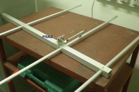 A 3 element yagi antenna project for the 144 MHz band by PY5ALZ in portuguese
 -
 Demonstrates the construction and measurement of a single-turn HF receiving loop antenna, built from common materials like electrical conduit and lamp cord. The resource details the physical dimensions, including a 4-meter circumference, and calculates the theoretical inductance at approximately _6.4 uH_. It outlines a method for determining resonant frequencies across the 4-17 MHz range using a _C Jig_ and a _VR-500 receiver_, coupling the loop with a ferrite ring. The article also discusses the impact of receiver coupling on the loop's Q factor, noting a degradation in sharpness due to the transformer's reflected impedance. Analyzes the observed resonant frequency patterns, highlighting an unexpected rise in the loop's effective inductance at higher frequencies, particularly above 13 MHz. While some increase is attributed to distributed capacitance, the rate of rise suggests further investigation. The experimental setup provides practical insights into the challenges of maintaining high Q in simple receiving loops and offers a comparative reference for other homebrew antenna projects, such as those by _VK2TPM_.
 -
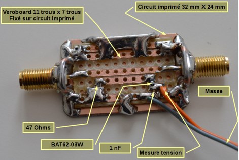 An home made SWR meter for 2.4 GHz. A DIY SWR meter that allow precise measurements and calibration of any WiFi antenna. This is test equipment everyone who build wifi antennas should have in their shack. Article is in french and include some videos.
 -
-
 GW4ALG's _136 kHz Pages_ document the evolution of vertical antennas for the 2200m band, starting with a prototype mounted on a house wall. This initial design, despite achieving the first **395 km** GM-GW QSO, suffered from significant insulation breakdown, high RF losses due to proximity to the house, and difficult tuning adjustments. The author details the challenges of maintaining resonance and matching with a variometer in the loft, noting that adding three earth spikes offered no measurable improvement over a simple water tap connection. The subsequent experimental 12m vertical, relocated away from the house, significantly reduced dielectric losses and proved far more effective. This antenna enabled GW4ALG to set a world DX record on 136 kHz with a **1916 km** QSO to OH1TN, and an intra-UK record of **703 km** to GM3YXM/P. The resource further explores the use of helium-filled balloons to extend the vertical radiator, achieving heights up to 27m, typically 20m, for enhanced low-band performance. Practical advice on balloon types, inflation, and critical insulation between the wire and balloon is provided, emphasizing safety and avoiding arcing.
 -
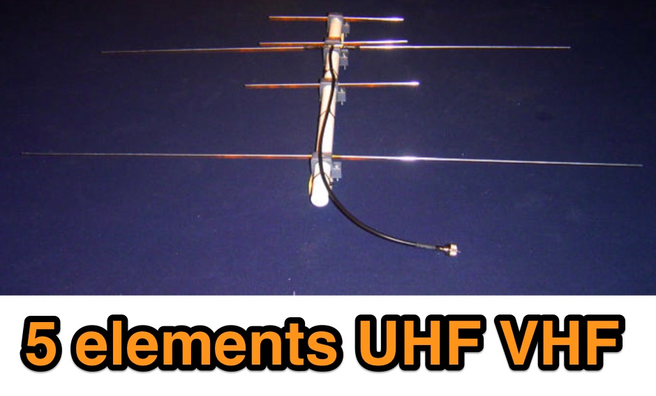 On this page is the design for Dual Band 2M / 70cm antenna with 3.2mm elements. The antenna has a 50 ohm designed driver. This Yagi has a unique element called a Open Sleeve
 -
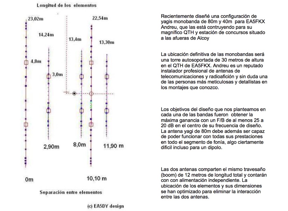 Design plan of an array of a two element yagis for 80m and a 3 element 40m antenna sharing a single 12 meters long boom by EA5DY
 -
 DK7ZB provides detailed construction plans for Moxon antennas utilizing tapered aluminum tubing, specifically outlining dimensions for 50 MHz, 28 MHz, 24 MHz, and 21 MHz bands. The resource emphasizes maintaining specific taper lengths for optimal performance and describes a tuning method involving symmetrical element shifts. It also addresses stacking considerations, noting that two Moxons can be stacked 1m apart with a 90° rotation to avoid severe detuning, unlike co-planar mounting. Performance figures for the 50-MHz Moxon include a gain of **4.1 dBd** and a front-to-back ratio of _30 dB_. The construction utilizes copper fittings for element connections, with a recommendation to varnish edges against corrosion. The page features images of built antennas by _DK8UH_ and VK2QO, illustrating practical implementations for the 6-meter and 10-meter bands, respectively.
 -
 A 2m Moxon antenna project, designed for the 145 MHz amateur radio band, provides a compact, directional solution for VHF communications. This resource details the construction process, specifying materials like PVC pipe for the frame, copper wire for elements, and a SO-239 connector for the feedpoint. The design emphasizes ease of build for hams seeking a gain antenna with good front-to-back ratio for local ragchewing or contesting. The project outlines precise element lengths and spacing, crucial for achieving the desired impedance and radiation pattern. It includes a visual representation of the antenna's dimensions and assembly, allowing for straightforward replication. The Moxon's inherent characteristics offer a practical alternative to larger Yagi arrays, particularly for portable operations or restricted spaces, while still delivering effective directivity and gain.
 -
 Christoph petermann's df9cy six element yagi antenna for six meter band
 -
 This QRZ.com callbook entry by DL6GD details the construction and performance of a **40m/80m Morgain folded dipole antenna**. The resource includes a schematic diagram, construction photos, and tuning notes. The antenna, with a total length of **20.30m**, was mounted at a height varying from 4m to 6m above ground. Construction utilizes 0.75 sq mm transparent insulated copper wire, with Plexiglas spreaders (5mm thick, 70x10mm) spaced at 25mm intervals, secured with hot glue. A waterproof junction box houses the feedpoint and balun. Tuning involved adjusting wire bridges for resonance on each band. On 80m, an SWR of **1.1:1** was achieved at 3.657 MHz, with an SWR of 2.7:1 at 3.580 MHz and 2.5:1 at 3.755 MHz, yielding a bandwidth of 175 KHz. For 40m, an SWR of **1.1:1** was measured at 7.100 MHz, with 1.5:1 at 7.000 MHz and 1.3:1 at 7.200 MHz, providing a 200 KHz bandwidth. DL6GD notes that 80m tuning exhibits slight height sensitivity, while 40m tuning is less affected by height or 80m adjustments. Long-term observations from 2014 and 2022 document SWR degradation due to environmental factors like spiderwebs and ice accumulation, which can cause HF-conductive paths between elements. DXZone Focus: Callbook Entry | 40m/80m Morgain Dipole | SWR Measurements | 20.30m Length
 -
 The document provides a detailed guide on modifying an inverted-L antenna to include the 160 meters band. This enhancement allows amateur radio operators to utilize the lower frequency effectively, which is crucial for long-distance communication, especially during the night. The inverted-L design is popular due to its compact size and ease of installation, making it suitable for various environments. By adding top band capabilities, operators can engage in DXing and contesting on 160m, expanding their operational range and opportunities. The guide includes practical tips and considerations for construction, ensuring that the antenna maintains its performance across the extended frequency range. It discusses the necessary adjustments and materials required for the modification, along with potential challenges and solutions. Whether you are a seasoned operator or a beginner, this project can enhance your station's capabilities, allowing for more versatile operations and improved signal quality on the 160m band.
 -
 A 500-watt mobile antenna project details the conversion of an old 10m hamstick into a highly efficient, multiband "bugstick" for HF operation. The core modification involves replacing the original coil with 25 turns of 6 turns-per-inch, 1.5-inch diameter coil stock, fabricated from #14 wire. This design, intended for a 3-magnet mount on a vehicle cab, achieves resonance on multiple bands by shorting out specific turns on the coil, similar to a **bugcatcher** antenna. Measurements taken with an MFJ-259 analyzer on a GMC pickup show 0 turns shorted for 20 meters (14.2 MHz), 10 turns for 17 meters, 16 turns for 15 meters, 19 turns for 12 meters, and 23 turns for 10 meters. The construction emphasizes using UV-resistant tie-wraps and #14 solid wire with crimp lugs for robust RF connections, bypassing the fiberglass rod for current flow. A bonus section details a 40-meter version, utilizing 48 turns of 8 TPI, 2-inch diameter coil stock.
 -
 Construction details and tests about a 2 elements cubical quad antenna for HF Bands (20,17,15,12 and 10m band).
 -
 The **2M Moxon antenna** design presented operates at 144 MHz, providing a compact, directional solution for VHF communications. Construction involves aluminum tubing for the elements, with specific dimensions for the driven element and reflector to achieve optimal performance. The design aims for a good front-to-back ratio and a relatively low SWR across the 2-meter band, making it suitable for portable or fixed station use where directivity is beneficial. Element lengths are critical for proper resonance and pattern. The driven element measures approximately 38.5 inches, while the reflector is slightly longer at 40.5 inches. Spacing between the elements is 12 inches, forming the characteristic Moxon rectangle. This configuration yields a gain of about 5.5 dBi and a front-to-back ratio exceeding 20 dB, which is advantageous for reducing interference from unwanted directions. Feedpoint impedance is close to 50 ohms, allowing direct connection to coaxial cable without complex matching networks. The antenna's lightweight structure, typically under 2 pounds, facilitates easy deployment and rotation, making it a practical choice for field operations or as a compact home station antenna.
 -
-
 The Moxon Beam, introduced by L. Moxon (G6XN), is a compact 2-element Yagi featuring a radiator and reflector with reduced dimensions, approximately 75% the size of a full-size beam. This design utilizes bent element ends for capacitive loading, which is superior to inductive loading with coils, resulting in greater bandwidth and lower losses. DK7ZB details that while the gain is slightly lower (0.5-0.7 dB) than a full-size beam, the _Moxon_ offers an exceptional front-to-back (F/B) ratio of 30 dB or more on its design frequency, surpassing other 2-element beams. The article provides specific dimensions for building wire _Moxon_ antennas for bands from 30m down to 10m, and also mentions a 2-m-Moxon. Construction guidance includes using fishing rods for lightweight spreaders and an aluminum tubing spider for support. The resource highlights the utility of _Moxgen_ by AC6LA, a freeware program that simplifies Moxon beam design and generates EZNEC output files for further analysis and tapering modifications. DK7ZB emphasizes that the design frequency should be set at approximately one-third from the band's beginning to optimize SWR performance, as SWR tends to rise more significantly below the design frequency. The bandwidth for SWR < 1.5 is noted as sufficient for ranges like 28.0-28.7 MHz and 21.0-21.45 MHz when constructed with aluminum tubes, though wire beams exhibit a narrower bandwidth.
 -
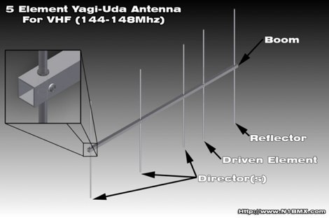 A project for a home made 5 element yagi-uda antenna for 2 meters, covering 144-148 MHz band by N1BMX
 -
 SimSmith is a highly interactive, real time Smith chart graphing program. Circuits are constructed using drag-n-drop. Load files can be imported from the EZNEC and CocoaNEC antenna simulation software and from the AIM4170 and miniVNApro antenna analyzers. Circuits and load files can be of any size. Key Features: SimSmith is one of the few Smith chart packages which models transmission line losses. SimSmith also allows the description of circuit elements using algebraic equations. SimSmith has only one screen and allows the screen to be resized to increase workspace or readability.
 -
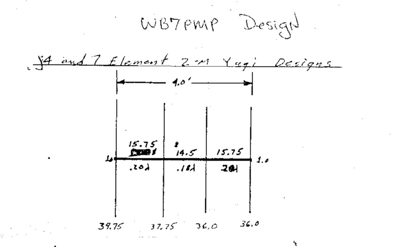 Original drawing and design of a 4 and 7 elements yagi antenna for 50 Mhz
 -
 Collection of different techniques to homebrew PVC yagi antennas, including elements assembling, baluns and chokes, radiator box tips and tricks by dk7zb
 -

-
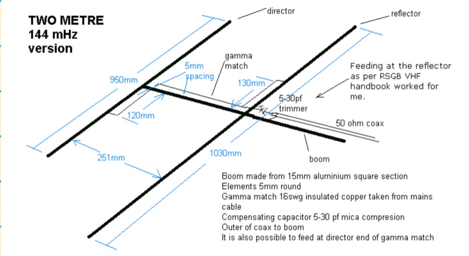 The HB9CV is a well known two element antenna of a directional beam type with a forward gain of 4 to 5 dBd. This one is for two metres but it can be scaled, from the dimensions in the diagram, for other bands I have also made them for four and six metres
 -