Search results
Query: step ir
Links: 134 | Categories: 0
-
 Operating the AO-51 amateur radio satellite with a handheld transceiver (HT) presents a practical entry point for newcomers to satellite communications. This resource details the necessary steps and considerations for making basic contacts, focusing on accessible equipment. It covers fundamental concepts such as _Keplerian elements_ for satellite tracking and the importance of understanding Doppler shift effects on both uplink and downlink frequencies. The tutorial outlines a straightforward approach to satellite passes, emphasizing the use of readily available gear. It provides insights into antenna orientation and timing for successful two-way communication. The content aims to demystify satellite operation, enabling operators to achieve their first **AO-51** contacts with minimal specialized equipment. Key aspects include frequency management and basic operational techniques.
 -
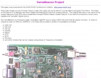 The VersaBeacon is a frequency agile, modulation agile RF source using a DDS chip and minimal support circuitry. It covers a frequency span of 1MHz to 150MHz in 1 Hz steps and provides a variety of modulations
 -
 A synthesized 2.3 GHz Amateur Television (ATV) transmitter design, conceived by Ian G6TVJ, is presented, targeting broadcast-quality video performance on the 13cm band and extending up to 2.6 GHz. The core of the design utilizes a commercial Z-comm Voltage Controlled Oscillator (VCO) that tunes from 2.2-2.7 GHz, providing a +10 dBm output and simplifying RF alignment. This VCO's stability, originally intended for narrowband applications, readily accepts high-frequency video modulation, contributing to the transmitter's robust performance. The exciter stage, incorporating a Mini Circuits VNA 25 MMIC amplifier, boosts the signal to +16dBm, while a Plessey SP4982 prescaler divides the output frequency for the synthesizer. The synthesizer employs a Motorola MC145151 CMOS parallel IC, favored over the common Plessey SP5060 for its superior video modulation characteristics and ease of programming without microprocessors. This choice addresses issues like LF tilt and distorted field syncs often seen with SP5060 designs, particularly when operating through repeaters or over long distances. The MC145151 divides the signal further, enabling precise frequency stepping, with programming handled by EPROMs for channel selection and LED display. The loop filter network, critical for video integrity, was developed through experimentation to prevent the PLL from reacting to video modulation, ensuring a clean transmitted picture. The transmitter incorporates a Down East Microwave commercial power amplifier module, delivering approximately 1.6W output, driven by the exciter through a 3dB attenuator. Construction involves surface-mount SHF components on micro-strip lines etched onto double-sided fiberglass board, housed within a tinplate box. The design boasts no AC coupling in the video path, preserving low-frequency response, a common failing in other ATV transmitters. Performance tests with a 50Hz square wave revealed no LF distortion, and a calibrated "Pulse & Bar" signal showed a near 100% HF response, demonstrating its capability for high-quality ATV transmissions.
 -
 This web article details the construction of a 4-meter band coaxial dipole antenna, designed for operation between **70.000 MHz and 70.500 MHz**. The resource provides a bill of materials and step-by-step assembly instructions for a half-wave dipole constructed from _RG-58_ coaxial cable. The design specifies a direct 50 ohm feedpoint impedance, eliminating the need for an external matching network. Construction photographs illustrate the stripping and soldering processes for the coaxial cable elements, ensuring proper electrical connection and physical integrity. The article includes specific dimensions for the radiating elements, derived from calculations for the 70 MHz band. The project outlines the physical dimensions required for resonance at 70 MHz, with the outer braid forming one half and the inner conductor forming the other. The feedline connection is directly to the coaxial dipole's center, maintaining a 50 ohm characteristic impedance. While the article does not present SWR plots or VNA sweeps, it focuses on the mechanical construction and dimensional accuracy for achieving a functional 4-meter dipole. The design is intended for fixed station use, with no specific mention of polarization or height above ground, but implies a standard horizontal orientation for dipole operation. DXZone Focus: Web Article | 4m Coaxial Dipole | Construction Guide | 50 ohm Feed
 -
 Mobile RFI, often manifesting as persistent noise in the receiver even with the antenna disconnected, frequently originates from the vehicle's power supply system. This guide details systematic troubleshooting steps, beginning with isolating the radio from the car's 12-volt supply to confirm the power system as the noise source. It emphasizes the critical importance of drawing power directly from the battery using **heavy gauge wire**, bypassing the fuse block to leverage the battery's natural capacitance for RFI suppression and ensuring a solid RF ground. Proper routing of power lines through the firewall is also covered, advocating for dedicated grommeted holes to prevent inductive coupling from other wiring harnesses. The article stresses the necessity of fusing both positive and negative leads from the battery, a crucial safety measure to prevent damage to the rig and mitigate high-current risks should the battery's engine block ground become compromised during service. Addressing **alternator whine**, a common high-pitched noise that varies with engine speed, the resource suggests checking battery connections and the alternator-to-battery harness for looseness or corrosion. It also mentions the utility of adding an external RF noise suppression capacitor in parallel with the alternator's internal capacitor for enhanced filtering, and the effectiveness of commercially available in-line power supply filters.
 -
 Demonstrates the complete design and development process for a **Low Noise Microwave Amplifier** (LNA), beginning with conceptual design and progressing through prototyping. The tutorial series covers the initial stages of a single-ended first gain stage, focusing on critical parameters such as noise figure, gain, and stability. It systematically details the theoretical underpinnings and practical considerations for achieving optimal performance in microwave frequency applications. This resource provides a structured approach to LNA construction, enabling radio amateurs and RF engineers to understand the iterative steps involved in realizing high-performance receive-side amplification. It offers insights into component selection, impedance matching networks, and the measurement techniques required to validate design specifications, particularly for **microwave** band operation where noise performance is paramount.
 -
 The AT-AUTO automatic antenna tuner handles 1.5kW CW operation, employing stepper motors under microprocessor control to precisely position a roller inductor and air-dielectric variable capacitor, avoiding relay-switched discrete components. This design choice prevents loud relay clacking and burning contacts, a common issue with competing products. The tuner features auto-retuning capabilities and receives periodic firmware updates, ensuring continuous improvement and added user-requested features. Its companion product, the _CX-AUTO_ coaxial switch, also features an embedded microprocessor controller. It enables selection of 1-of-8 coaxial outputs via a serial data interface. When integrated with the _AT-AUTO_, the tuner can associate specific coaxial outputs with amateur radio bands, automatically commanding the _CX-AUTO_ to select the correct antenna when the operator QSYs to a different band. Don Kessler began designing the AT-AUTO in 2005, with its debut at the 2006 Dayton Hamvention. Kessler Engineering also offers custom RF product design and electrical engineering consulting, specializing in Class-E RF amplifiers.
 -
 Installing a mobile rig in a vehicle requires careful planning and execution to ensure optimal performance and safety. The process begins with selecting the right equipment, such as the ICOM IC706MKII for low bands and the ALINCO DR-610 for VHF/UHF operations. Proper mounting is crucial; both radios are strategically placed under the back seat of the Silverado, allowing for a clean installation while maintaining passenger comfort. The Hustler antenna, equipped with various resonators, ensures coverage across multiple bands, while the LDG automatic antenna tuner fine-tunes the match for efficient operation. A remote head for the tuner enhances accessibility, making adjustments easier while driving. Each step of the installation is documented to provide insights and tips for fellow operators looking to enhance their mobile setup. The experience shared here reflects practical knowledge gained through hands-on work, aiming to inspire others in the ham community to undertake similar projects.
 -
 Constructing a high-performance RF spectrum analyzer up to 1000 MHz requires careful attention to component selection, shielding, and circuit isolation. This resource details a project that improves upon the _Spectrum Analyzer for the Radio Amateur_ design by Wes Hayward (W7ZOI) and Terry White (K7TAU), incorporating ideas from Scotty Sprowls' project, particularly his 1013.3 MHz IF bandpass cavity filter. The analyzer utilizes a Mini-Circuits SRA-11 mixer with a sweeping local oscillator from 1013 to 2013 MHz, feeding into a 4-pole copper pipe cavity filter. The design employs a second SRA-11 mixer with a fixed 1024 MHz LO to produce a 10.7 MHz final IF. This signal then passes through narrowband resolution filters and is processed by Analog Devices AD603 and AD8307 ICs for IF amplification and logarithmic detection, driving an oscilloscope in X/Y mode. The project emphasizes modular construction, using salvaged components and double-sided FR4 material for PCBs, with critical notes on minimizing spurious images through effective shielding and proper voltage regulation for each module. Key components include a Z-Communications V585ME48 VCO for the first LO and a Z-Comm V583ME01 VCO controlled by a Motorola MC145151 PLL for the second LO. An optional Hittite HMC307 step attenuator and K&L 5L121-1000/T5000-O/O low-pass filter manage RF input. Tuning procedures for the 10.7 MHz IF resolution filter are also detailed, showing before-and-after spectrum views.
 -
 This resource is an online tutorial focused on setting up the Raspberry Pi for amateur radio applications. It covers the installation and configuration of various software packages tailored for digital communications and protocols, including _Packet Radio_ with Hamlib and Direwolf, as well as data modes like FLDigi and WSJT-X. The guide also details the integration of hardware components such as GPS clocks for time synchronization and real-time clocks for enhanced functionality. Users will find instructions for installing software like GPredict for satellite tracking and GQRX for software-defined radio (SDR) applications. The tutorial emphasizes practical steps, including the use of command-line inputs in the Raspberry Pi OS terminal, and provides troubleshooting tips for common issues such as faulty SD cards or insufficient power supplies. Operators are encouraged to explore various applications, including APRS iGates and WSPR beacons, to enhance their ham radio experience. The material is designed for licensed amateur radio operators with basic knowledge of electronics and computing.
 -
 An Google Maps interactive layer showing Australian amateur radio repeaters. You can navigate and zoom as required and click on a repeater-site icon to display frequency, ctcss and other details and notes for that repeater.
 -
 Presents _Beam Quest_, the official Japanese distributor for _SteppIR_ antennas, detailing their product lineup and services. The site showcases various _SteppIR_ Yagi models, including the _Dream Beam_ series (DB42, DB36, DB18E, DB11) with configurations from two to four elements, alongside the _Big IR_ and _Small IR_ vertical antennas. It also lists accessories such as TX/RX and PC interfaces, essential for integrating these advanced antenna systems into a ham shack. Operators often seek out _SteppIR_ antennas for their dynamically adjustable element lengths, which allow for optimization across multiple bands, a significant advantage for DXing and contesting. This adaptability contrasts sharply with fixed-element Yagis, providing a distinct edge in varying band conditions. The resource provides contact information, including email and phone numbers, for inquiries and support regarding _SteppIR_ products within Japan, serving as a direct point of contact for sales and technical assistance.
 -
 Presents the full owner's manual for the _Drake R-4C_ communications receiver, specifically a late version edition. This resource outlines the comprehensive operational instructions, covering everything from initial setup and tuning to advanced features and controls. Hams can reference detailed diagrams and explanations for proper signal reception across various amateur bands. The manual includes critical information for alignment procedures, ensuring the receiver performs to its optimal specifications. It details the steps required for calibrating the internal circuitry, which is essential for maintaining sensitivity and selectivity over time. My experience with vintage Drake gear confirms the value of these original documents for accurate adjustments. Furthermore, the document provides insights into troubleshooting common issues and performing routine maintenance. It serves as an authoritative guide for anyone operating or servicing this classic piece of amateur radio equipment, helping to preserve its functionality for years of DXing and ragchewing.
 -
 Italian ham radio dealer for major brands like Icom Kenwood Yaesu HY-GAIN Heil Sound Rigexpert Palstar GAP antennas Diamond SteppIR and others
 -
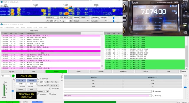 The _Icom IC-7300_ transceiver, a popular SDR rig, can be readily configured for digital modes like FT8 using _WSJT-X_ software. This guide details the necessary steps, from downloading the correct version of WSJT-X to configuring the radio's USB audio and CAT control settings. It emphasizes a straightforward approach, aiming to simplify the often complex initial setup for new digital mode operators. K0PIR shares his practical experience, outlining the specific menu settings on the IC-7300, such as USB SEND/DPT and USB MOD LEVEL, which are crucial for proper signal modulation and transmission. The resource also covers the integration of WSJT-X's built-in logging capabilities, streamlining the process of recording digital contacts without needing external logging software immediately. This setup allows for efficient operation on various HF bands. Two embedded videos further illustrate the configuration process, providing visual aids for each step, from initial software installation to making the first FT8 contact. The author's method focuses on minimizing common setup hurdles.
 -
 Sell quality electronic components, equipment, and accessories. Test equipment, RF Modules, Power supplies, PCB, Stepper motors.
 -
 A 0-30 MHz step attenuator, constructed from switchable Pi attenuation pads, provides a practical tool for evaluating receiver sensitivity and calibrating S-meters. The design utilizes readily available 5% tolerance resistors, with values derived from paralleled components to achieve specific attenuation steps. A schematic (Fig 1) illustrates the circuit, including PCB pad shielding, while a table details required and actual resistor values, along with percentage differences. Measurements of voltage input versus output at various frequencies are used to calculate dB attenuation, presented in a graph (Fig 4). The resource includes formulas for determining output voltage from a known input and a comprehensive 0-40 dB voltage multiplier table, which is crucial for precise signal level management. The project also references external attenuator calculators and equations for further study. Photos (1-3) provide visual guidance for the assembled unit, showing bottom, top, and front views. The project emphasizes the use of **Pi attenuation pads** and **receiver sensitivity** evaluation, offering a hands-on approach to RF signal management.
 -
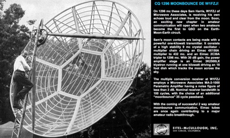 The first EME history was written in 1944 when first EME echoes were received on 564 MHz by German Wurzmann radar according to the article by Dr. Ing. W. Stepp.
 -
 A 20-meter window frame stealth antenna, based on a design by _PD7MAA_, utilizes a single 620cm wire loop for discreet installation. The feeding mechanism employs a _4C65_ toroidal core, where the antenna loop functions as a single-turn secondary, and the feedline wraps twice. Tuning is achieved via a 30cm twisted wire stub, allowing for SWR adjustment within the 20m band. This design is specified for QRP operation, with a maximum power limit of **25 Watts** to prevent core saturation or arcing. Wire selection recommendations include thin, insulated copper wire (0.75mm to 1mm) for blending with architectural elements. The guide focuses on practical construction steps for a low-profile 14MHz antenna.
 -
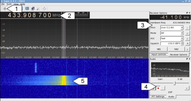 Analyzing 433 MHz radio signals from common wireless devices, such as temperature sensors and remote controls, involves understanding **On-Off Keying (OOK)** modulation. This resource details the process of capturing these signals using a Software Defined Radio (SDR) like Gqrx and then visually inspecting the captured audio data in a sound editor such as Audacity. It differentiates between **Pulse Width Modulation (PWM)** and Pulse Position Modulation (PPM) encoding schemes, illustrating how to identify and decode binary data by eye based on pulse and gap durations. The article provides a step-by-step walkthrough for decoding a wireless thermometer's data, correlating bit patterns with known temperature, humidity, and channel values. It also demonstrates decoding an RF remote control's button presses, highlighting the constant and varying parts of the transmitted packets. The content further introduces automated decoding using tools like RTL_433, explaining its capabilities in parsing various device protocols and showing how to interpret its output, including modulation type and decoded data. Specific examples include analyzing Prologue sensor protocol specifications from RTL_433's source code and noting common operating frequencies like 433.92 MHz in Europe and 915 MHz in the US.
 -
 The DIY 137 MHz WX SAT V-dipole antenna project details the construction of a specialized antenna for receiving weather satellite transmissions. It provides specific dimensions for the dipole elements, designed for optimal reception around the 137 MHz band, which is commonly used by NOAA and Meteor weather satellites. The resource outlines the materials required, such as aluminum tubing for elements and PVC for the support structure, along with the necessary coaxial cable and connectors. The article presents a clear, step-by-step assembly process, including how to form the V-shape and connect the feedline. It emphasizes practical considerations for mounting and weatherproofing the antenna for outdoor deployment. The design focuses on simplicity and effectiveness for amateur radio operators interested in satellite imagery. Key aspects include the precise angle of the V-dipole and the lengths of the radiating elements, which are critical for achieving the desired circular polarization response for satellite signals. The resource includes photographic documentation of the construction phases and the final mounted antenna.
 -
 Clarifies the intricate process of calibrating the _Elecraft K2_ dial, addressing common user challenges and lively discussions on the Elecraft reflector. Wilhelm, W3FPR, dissects the K2's PLL synthesizer design, chosen for its low phase noise, kit-friendly duplication, and cost-effective components. The resource emphasizes the critical role of the 4000.000 kHz reference oscillator's accuracy during CAL PLL, CAL FIL, and CAL FCTR functions, noting its dependence on temperature and crystal stability for optimal performance. Explaining the K2's frequency display, the document reveals it relies on microprocessor-driven look-up tables generated by CAL PLL for VFO values and CAL FIL for BFO values. In SSB and RTTY, these combine, while CW and CWr modes also factor in the sidetone pitch. The author details inherent limitations, such as the 10 Hz increment resolution of the dial and varying PLL step sizes—from 3 Hz on 160 meters to 10 Hz on 10 meters. BFO increments range from 20 to 35 Hz, collectively limiting practical dial accuracy to within **20 Hz** with diligent effort, or **30 Hz** for a slightly less demanding task. The guide outlines a four-step calibration procedure: setting the reference oscillator, running CAL PLL, running CAL FIL, and setting all BFOs. It highlights the _N6KR Method_ as a particularly easy and accurate approach, requiring only the K2 and a known frequency source like WWV for zero-beating, eliminating the need for external test equipment.
 -
 Tysonpower details a DIY AZ/EL antenna rotator project designed for under €150, inspired by the Satnogs Tracker. Constructed with 2020 aluminum extrusion and NEMA23 stepper motors, the rotator is controlled via an Arduino Nano. It effectively tracks smaller antennas like Yagi, though struggles with heavier dishes. STL files are available on Thingiverse.
 -
 A review of the SteppIR UrbanBeam antenna a two element Yagi antenna working 40-6 meters. The UrbanBeam is a good choice for those thare are limited by lot size, regulations, city regulations.
 -
 This PDF guide provides detailed instructions and diagrams for constructing a fan dipole antenna, a popular choice among hams for multiband operations. The guide covers the design, materials needed, and installation process, offering step-by-step guidance to help hams set up an effective antenna system for their radio operations.
 -
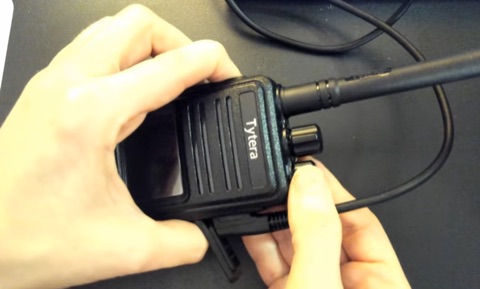 A step by step instruction on how to upgrade firmware on the Tytera MD-380 DMR
 -
 Enables operators to search the XR0ZRC DXpedition log online, a service facilitated by **Club Log**. This tool allows for rapid **QSO verification**, confirming contacts made with the XR0ZRC entity. Users can input their callsign and other contact details to ascertain if their signal report and time match the DXpedition's records, a critical step for award applications like DXCC. The platform offers a straightforward interface for checking log entries, which is particularly useful for those chasing new entities or band slots. It integrates seamlessly with the broader Club Log ecosystem, providing a reliable method for operators worldwide to confirm their DX contacts without requiring a login, reflecting the utility of real-time log updates in the amateur radio community.
 -
 Learn how to easily build a 10-meter vertical antenna, perfect for DX contacts on the amateur radio bands. This flowerpot or T2LT design is portable, efficient, and ideal for ham radio operators looking to improve their DX performance. With just a few basic tools and materials, you can construct this antenna for portable operations or as a home station setup. Discover how to set up the antenna, improve its performance by raising it higher, and start making contacts with stations around the world. Watch a step-by-step guide on YouTube for building and testing this DIY ham radio antenna.
 -
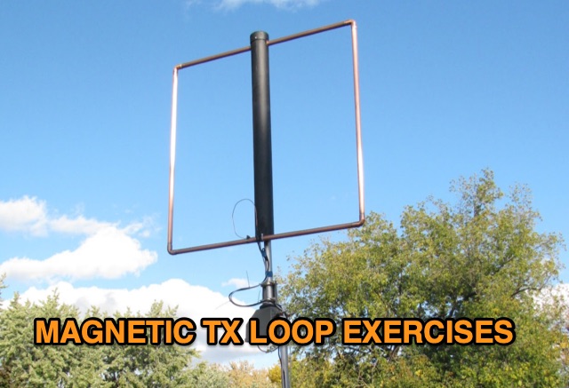 Explore two magnetic loop antenna constructions, utilizing a 6-foot and a 12-foot square loop. Accompanied by a detailed description, the 6-foot loop features a built-in stepper motor control circuit, while the 12-foot loop incorporates a separate loop controller. Efficiency, tuning ranges, and the innovative autotuning solution using a microcontroller are discussed, offering insights into overcoming the antenna's narrowband limitations.
 -
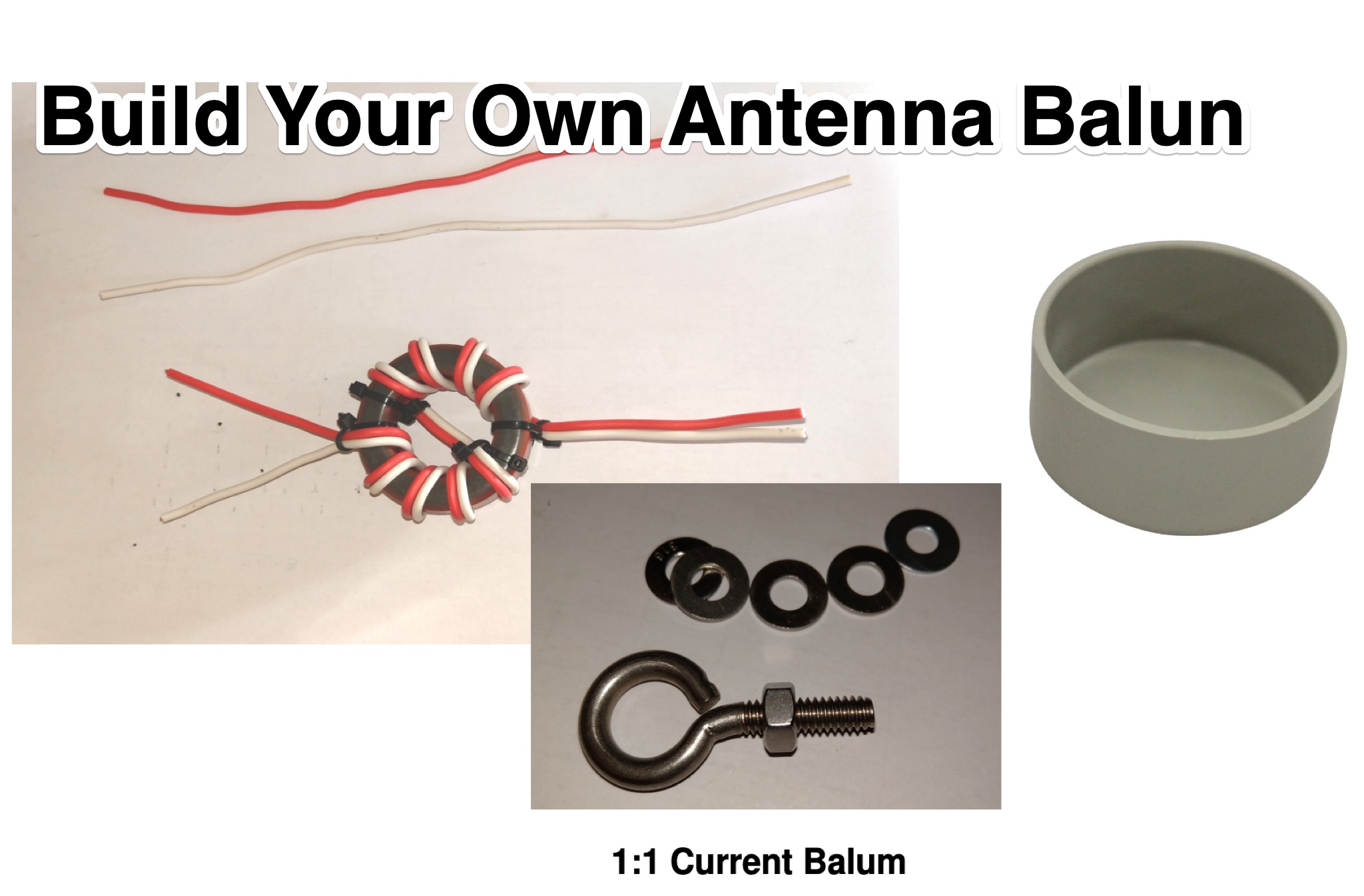 This PDF guide provides step-by-step instructions on how to build a Bunnings Balun for your ham radio antenna. A balun is essential for matching the impedance between your antenna and radio, improving signal transmission. The guide is perfect for hams looking to enhance their radio setup on a budget. Follow the detailed instructions to create your own balun using easily accessible materials from Bunnings or any hardware store.
 -
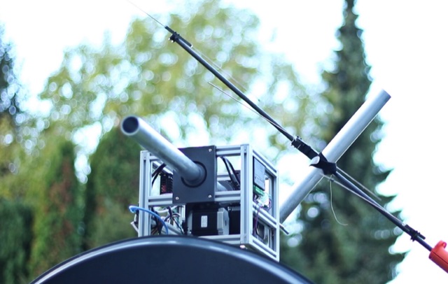
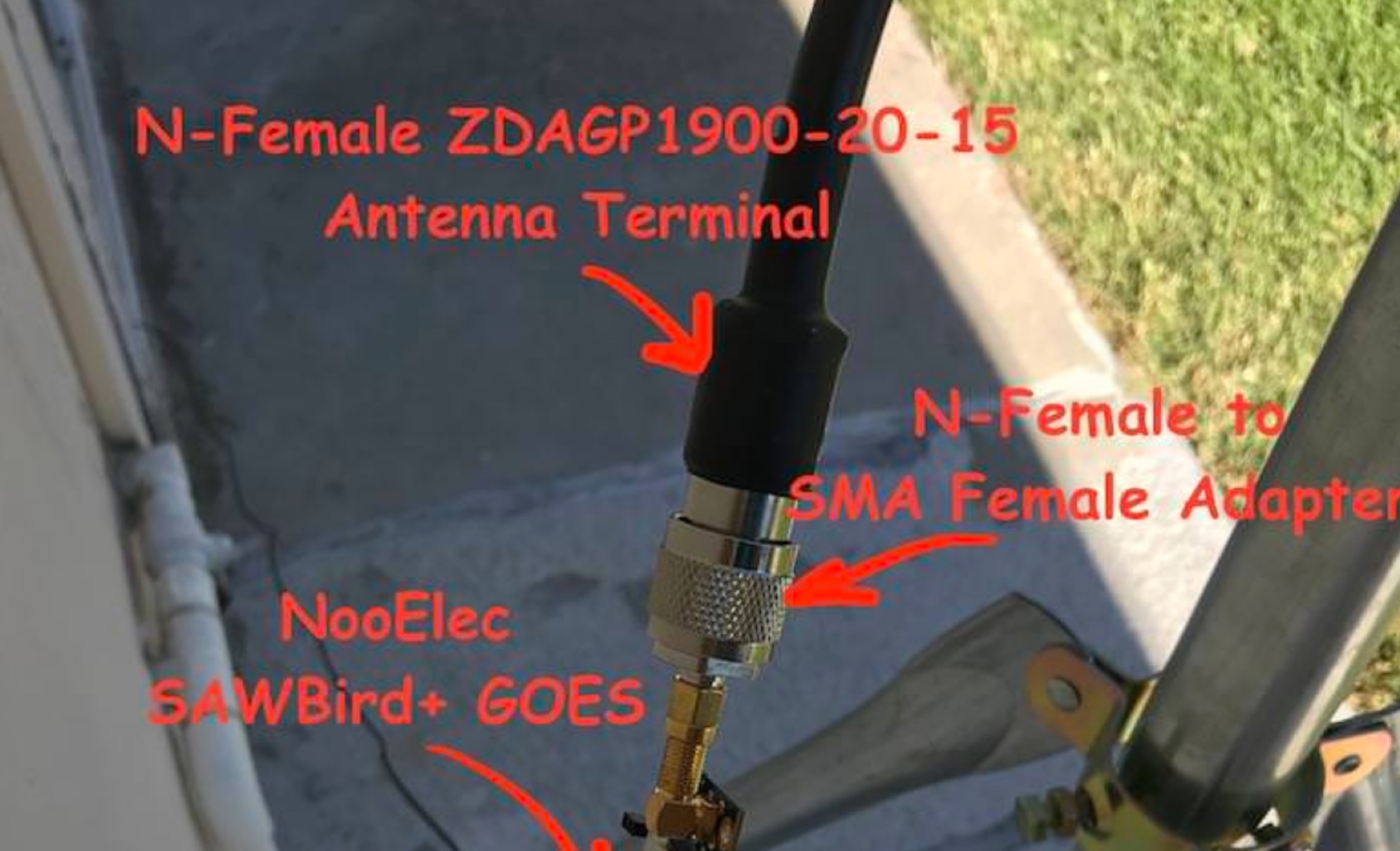 Receiving **GOES-16** and **GOES-17** weather satellite imagery requires a specific hardware and software configuration, detailed in this practical guide. The author outlines the necessary components, including a Raspberry Pi, an RTL-SDR dongle, a suitable LNA with SAW filter for 1.69 GHz, and a parabolic grid antenna. This setup enables direct reception of high-resolution weather data, a fascinating aspect of amateur radio satellite operations. The installation process begins with preparing the Raspberry Pi, followed by updating the system and installing essential dependencies like `git`, `build-essential`, and `cmake`. A critical step involves compiling and installing `librtlsdr` from source, ensuring proper driver setup and blacklisting conflicting DVB drivers. The guide then walks through testing the RTL-SDR dongle to confirm device recognition and troubleshoot common issues like USB power or driver installation problems. Finally, the instructions cover cloning and building `goestools`, a software suite essential for processing the satellite signals. This compilation, while time-consuming on a Raspberry Pi, is crucial for decoding the raw data into usable imagery. The guide concludes with the initial steps for creating the `goesrecv.conf` configuration file, preparing the system for active satellite reception.
 -
 This page by Keith Greiner describes a magnetic loop antenna project, providing step-by-step instructions to create two versions of a system with one large loop and one small loop. It includes details on how to construct the loops using different materials, along with the necessary equipment like antenna analyzers, tuners, and software. The page is divided into five sections covering project discussion, design summary, an improved small loop, construction steps, and radiation pattern analysis. Aimed at hams interested in building their own magnetic loop antennas, the page offers practical guidance and insights into impedance matching for improved performance.
 -
 Building an End-Fed Half-Wave (EFHW) antenna from a kit, as detailed by Frank Bontenbal, PA2DKW, with process photos by Bob Inderbitzen, NQ1R, offers a practical approach for hams. This specific kit, a collaboration between ARRL and HF Kits, targets 10, 15, 20, and 40 meters, making it a versatile option for HF operations. Unlike a center-fed dipole, the EFHW is a half-wavelength antenna fed at one end, which simplifies deployment, particularly for portable use. The construction guide meticulously outlines the assembly of the 49:1 impedance matching network, crucial for transforming the antenna's high impedance (around 2,500 Ohms) to a transceiver-friendly 50 Ohms. Steps include preparing the enclosure by drilling holes for the coaxial connector and antenna connections, followed by the precise winding of enameled copper wire onto a toroid to create the transformer. The guide emphasizes careful insulation removal and soldering for reliable connections. Final assembly involves integrating a 100 pF capacitor for higher band compensation, soldering the transformer's primary and secondary sides, and conducting SWR tests with a 2K7 resistor or a half-wavelength wire. The document also provides examples of wire lengths for different bands, such as 16 feet for 10 meters or 66 feet for 40 meters, demonstrating the transformer's adaptability for various half-wavelength configurations.
 -
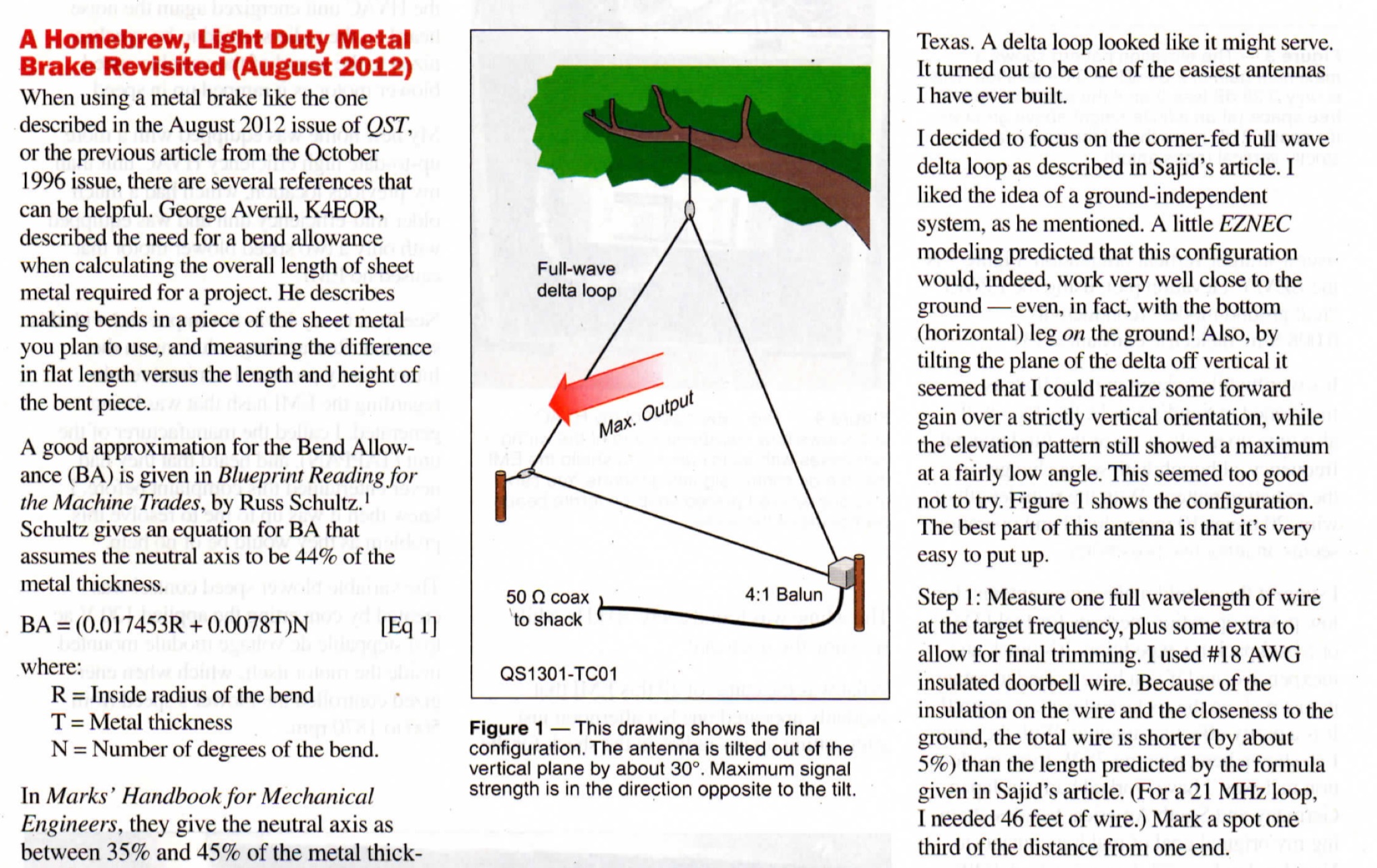 This guide provides step-by-step instructions on how to install a delta loop antenna for hams. It covers the necessary materials, tools, and installation process in a clear and concise manner. Whether you're a beginner looking to set up your first antenna or an experienced ham radio operator wanting to try a new antenna design, this guide is a valuable resource to enhance your radio communication setup.
 -
 LZ1AQ describes a versatile QRP antenna tuner that switches between Pi and Tee configurations with a single toggle. Using two variable capacitors and a seven-switch stepped inductor providing 128 increments (0.16 to 18.7 uH), this compact design handles 3.5 to 28 MHz with excellent matching range. The Pi mode works best for certain impedances while Tee mode proves more universal, matching loads the Pi cannot. Built in a plastic enclosure using salvaged radio capacitors, the tuner operates reliably up to 100 watts with proper antennas, though it's optimized for QRP service with random wires.
 -
 This practical, hands-on article offers a valuable journey through balun construction for portable antenna systems. The author skillfully navigates from theoretical debates to practical implementation, providing a well-documented DIY process using RG316 micro coax and an FT114-43 toroid core. The step-by-step instructions, complemented by photographs, make this complex technical project accessible to hobbyists. Particularly impressive is the author's focus on lightweight design (just 173 grams) for SOTA field operations. While the final antenna requires minor tuning adjustments, the successful field test during the Pirate Contest demonstrates the effectiveness of this approach. An excellent resource that transforms theory into practical application for ham radio operators.
 -
 A coaxial cable trap is a fundamental component in multiband antenna design, enabling a single radiator to resonate efficiently on multiple frequencies by electrically shortening or lengthening the antenna element. This project focuses on constructing such a trap for a vertical antenna operating on the 10 MHz (30m) and 14 MHz (20m) amateur bands, providing practical insights into its fabrication and integration. The article outlines the specific dimensions and winding techniques for the coaxial trap, emphasizing the use of readily available materials. It details the physical construction of the vertical element, including the mast and radiating sections, to achieve optimal performance across both target bands. The author shares personal experiences with similar trap designs, noting their effectiveness in previous horizontal dipole configurations. Key construction steps are illustrated with _original photos_, showing the assembly of the trap and its incorporation into the overall antenna structure. The design aims for a compact footprint, making it suitable for limited space installations while still delivering effective DX capabilities on the **30-meter** and **20-meter** bands.
 -
 Learn how to design and analyze a folded trifilar antenna for the 80-meter band. Based on a description from RAF antennas between 1940 and 1970, this article provides step-by-step guidance on modeling the antenna, calculating resonance frequency, adjusting dimensions, and verifying performance. Perfect for hams looking to improve their antenna setup for better transmission and reception on the 80M band.
 -
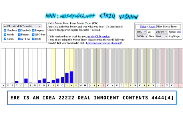 The **Nilex Morse Tutor** is an HTML5 web application designed to teach Morse code reception, adapting to user proficiency by adding new characters as readiness is detected. It prioritizes practice on less familiar letters, numbers, symbols, words, and phrases, while minimizing repetition of already mastered elements. The program offers multiple learning orders, including "Q7ZG..." (Ward/Jim's), "KMRS..." (PU5EPX/Koch), "KMUR..." (lcwo.net), "AENT..." (CWops CW Academy), "TEAN..." (Stephen C Phillips), "ANET..." (Vic VE3YT), and "ETI5..." (Ham Whisperer), alongside an alphabetical option. Users can customize the learning experience by enabling or disabling automatic progression, and selecting specific content categories such as numbers, symbols, words, phrases, QSO bits, Ham Radio Bands, X+Y=Z math, and units. Audio settings are adjustable for volume, speed (WPM), tone frequency, and keyshape/keying envelope, allowing for a personalized auditory environment. The interface provides visual feedback with blue bars indicating practice emphasis and gray bars for reserved characters, with clickable bars for manual character selection. Developed by "Nosey" Nick Waterman, VA3NNW, this tutor is based on earlier versions by Jim Wilson and a 1977 QST article. A significant October 2019 rewrite incorporated a new WebAudio sound library by AwesomeAidenW, improving offline functionality and mobile support. The content library was expanded to include 3000 top Google words, 2284+ General Service List words, ISO country codes, capital cities, US states, Canadian provinces, UK counties, common names, periodic table elements, quotes, Q-codes, electronic components, ham abbreviations, and example call signs. The software is distributed under the GNU GPL V2 license.
 -
 The Squirrel Cannon article humorously recounts the author's struggle with troublesome squirrels and his creative efforts to deal with them. Frustrated by failed attempts using bamboo spears and slingshots, the author ultimately constructs a spud gun—originally intended for launching antennas into trees, but humorously rebranded by his wife as a "squirrel cannon." The article provides step-by-step instructions, a parts list, and a line drawing for building this practical spud gun, making it a useful tool for antenna enthusiasts while serving as an amusing anecdote.
 -
 Presents a detailed construction guide for a 9 dB, 70cm collinear antenna, utilizing readily available _RG58/U_ coaxial cable and PVC pipe for housing. The resource outlines the critical calculations for ½ wavelength sections at 444 MHz, incorporating the coaxial cable's velocity factor of 0.66, which yields a section length of 223 millimeters. It specifies the preparation and soldering of eight such half-wavelength sections, each cut to 231mm to allow for trimming, forming the core of the array. Further instructions detail the integration of a ¼ wave element (169mm #16 solid wire) at the top and a ¼ wave aluminum tube (160mm, 5/16 inch) at the bottom, crimped to the feed point's braid. The guide also addresses RF common mode current suppression by suggesting the use of _FT50-43_ toroids on the feedline. Final assembly steps cover mounting the antenna within ¾" PVC pipe using a wooden dowel, waterproofing connections, and initial SWR checks. The article also discusses scaling the design for different element counts and other VHF/UHF bands.
 -
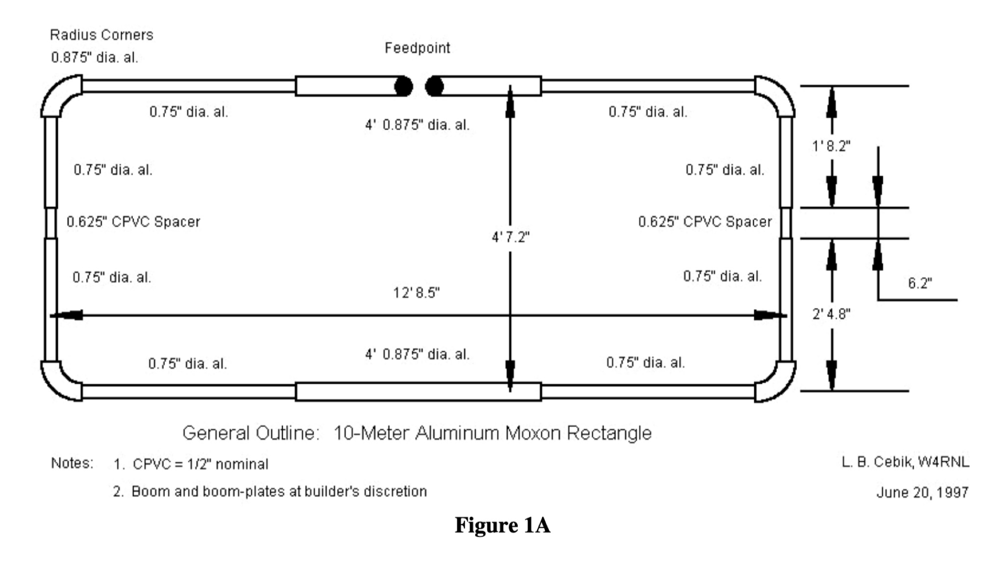 This PDF document provides a comprehensive guide on building and using the Moxon Rectangle antenna design for hams. It covers the construction, setup, and tuning of this directional antenna, offering practical advice and tips for amateur radio operators looking to improve their signal reception and transmission capabilities. The guide includes diagrams, measurements, and step-by-step instructions to help hams successfully implement the Moxon Rectangle design for their radio communication needs.
 -
 Presents two distinct hardware modifications for the Icom IC-7300 transceiver, detailing the necessary steps for each. The first modification, a _MARS_ transmit expansion, involves the physical removal of specific surface-mount diodes (D422) from the main board, enabling transmit capabilities across a broader frequency range, including out-of-band frequencies. It specifies the diode location on US versions of the IC-7300 and suggests using small diagonal cutters if a soldering iron is not preferred or available. The second modification focuses on the internal antenna tuner, aiming to provide wider impedance matching capabilities. This involves adding a **100k ohm** resistor to a designated point within the tuner circuit. The resource also briefly mentions a microphone modification for the _HM219_ and a general power increase, though without specific instructions for the latter two. It emphasizes safety precautions, such as disconnecting power and inspecting the work area.
 -
 A Magnetic Loop Controller project details the construction and operation of an automatic tuning system for magnetic loop antennas, which are resonant circuits using an oversized inductor and an adjustable capacitor. The system employs a stepper motor to precisely adjust the variable capacitor, maintaining optimal resonance across the HF bands. It integrates with various transceivers, including _Icom_, _Kenwood_, and _Yaesu_ models, by monitoring the VFO frequency and adjusting the loop's tuning accordingly. The project provides comprehensive building instructions, a PowerPoint-style presentation, and the full source code for the controller's firmware, enabling hams to replicate and customize the design. The controller's firmware offers diverse functionality, including automatic frequency tracking, manual tuning, and SWR monitoring, significantly enhancing the operational efficiency of magnetic loop antennas, particularly for QRP and portable operations. The design emphasizes accurate capacitor positioning, crucial for achieving low SWR and maximum radiated power. Comparisons with manual tuning methods highlight the benefits of real-time adjustment, especially when operating across different bands or making frequent QSYs. The project's detailed documentation and available source code facilitate experimentation and modification by advanced builders, allowing for tailored performance characteristics.
 -
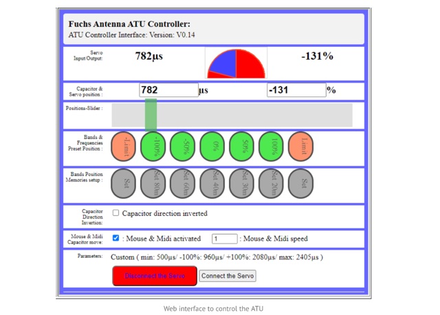 The Fuchs Antenna tuner with a resonant circuit as a coupler. The Fuch Antenna Tuner is providing a high-efficiency compare to a 49:1 transformer using ferrite . The Fuchs tuner is a resonating L/C circuit to step-up the impedance from 50 Ohm to the required 3k. The ATU is able to perform automatic tuning with the addition of a tiny Aduino Nano and a SWR bridge.
 -
 Notes, hints and tips on starting with morse code, how to approach learning the code, how and when to get on the air, learning and using abreviations, common Q-Codes and a sample morse code QSO.
 -
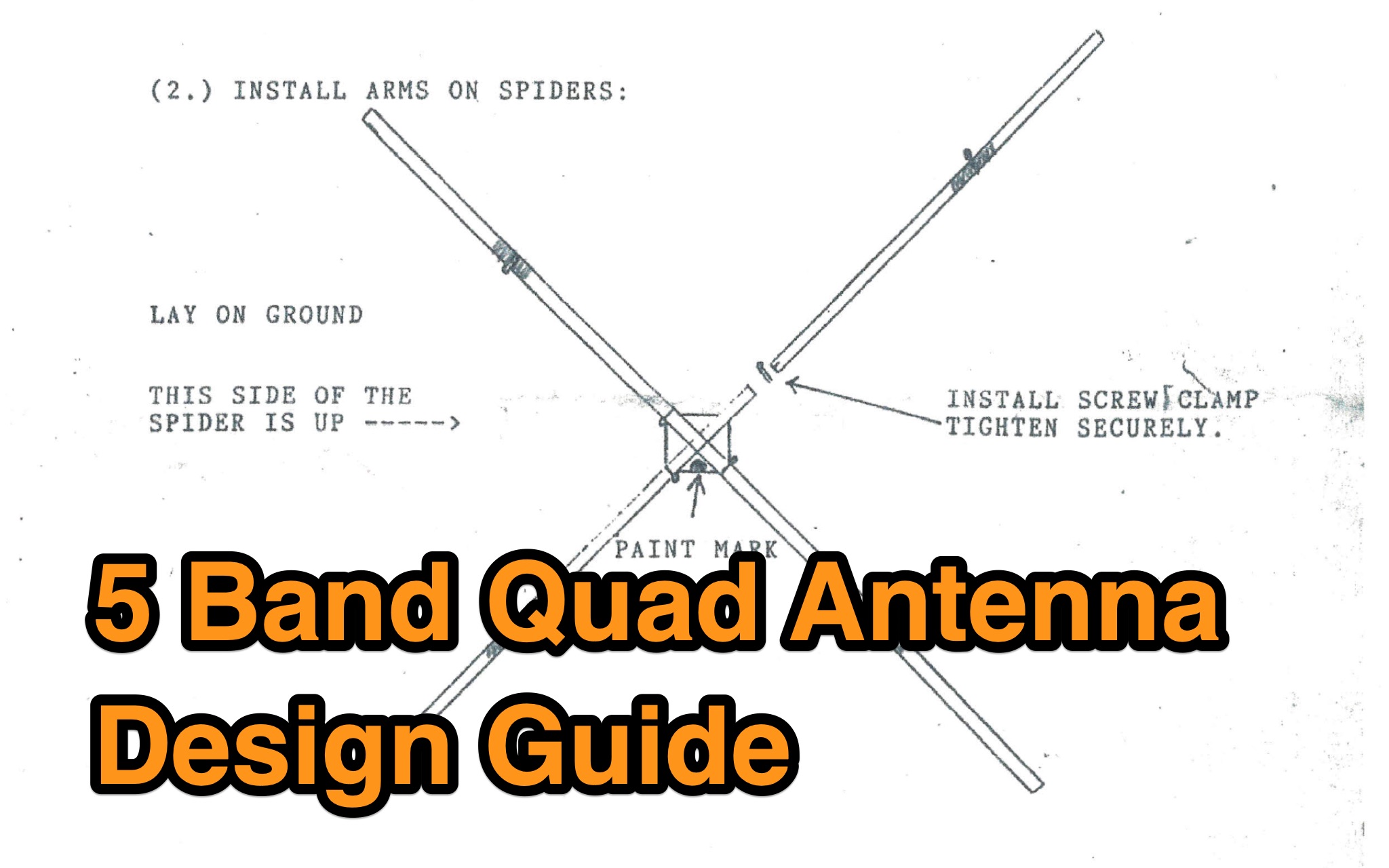 This guide provides detailed information on designing a 5 Band Quad Antenna for ham radio operators. It covers the necessary materials, dimensions, and construction steps required to build the antenna. The guide aims to help hams optimize their antenna setup for maximum performance on five different bands. Whether you are a beginner or an experienced operator, this resource can assist you in creating an effective antenna system for your station.
 -
 This project details the construction of a compact, circularly polarized Quadrifilar Helix Antenna (QHA) designed for 146 MHz operation. The antenna features a 1/2λ1/2λ helical design with a 2.6:1 aspect ratio, providing 4.5 dB gain and a spheroid radiation pattern. It is ground plane independent and compatible with both vertical and horizontal polarizations, making it ideal for terrestrial and space communications. The design includes step-by-step instructions for building the antenna using readily available materials like aluminum rods, PVC pipes, and RG-58 coaxial cable. The antenna's performance has been validated through comparisons with commercial omnidirectional antennas, showing superior results.
 -
 Constructing an effective antenna support system often involves safely elevating wire antennas into trees or over obstacles. This resource details the build process for the WT8WV "Colossus" air cannon antenna launcher, a pneumatic device designed to project a pilot line over elevated structures. It specifies the use of readily available PVC pipe components and standard hardware, outlining the exact materials required and providing step-by-step assembly instructions for a robust, low-cost solution. The article presents a practical alternative to traditional methods like slingshots, emphasizing the launcher's utility for Field Day operations and general antenna deployment. It includes a comprehensive list of parts, such as 2-inch and 1-inch PVC pipe, various fittings, a sprinkler valve, and a bicycle pump valve, detailing their integration into the final assembly. The total cost for materials is estimated at around $40 per unit, making it an accessible project for many radio amateurs. Crucially, the guide incorporates essential safety precautions for operating a pneumatic launcher, covering aspects like pressure management and projectile selection. It also features multiple photographs illustrating the construction phases and the completed device, offering visual clarity to aid builders in replicating the design.
 -
 Learn how to build a simple tuned loop antenna for the AM broadcast band to improve the performance of your radio receiver. Discover how to construct a loop antenna with readily available materials, such as balsa and basswood, without the need for specialized woodworking tools. Follow step-by-step instructions to create a portable loop antenna that offers good gain and directivity, ideal for pulling in weak stations. Enhance your Ultralight DX'ing experience and explore the world of FSL antennas through this practical DIY project.