Search results
Query: antenna project
Links: 563 | Categories: 26
Categories
- Antennas > 40M > 40 meter Delta Loop Antennas
- Antennas > 40M > 40 meter Yagi Antennas
- Antennas > 12M
- Antennas > 20M
- Antennas > 2M
- Technical Reference > Arduino
- Antennas > Bazooka
- Software > Circuit Design
- Antennas > Feed Lines
- Antennas > Horn
- Antennas > Log Periodic
- Technical Reference > LoRa and LoRaWan
- Antennas > Feed Lines > Open Wire
- Ham Radio > Personal Pages
- Operating Modes > QRP
- Antennas > Quadrifilar Helix
- Antennas > Receiving
- Antennas > Resonant Feedline Dipole
- Antennas > Satellite
- Antennas > Slim Jim
- Antennas > Spiral
- Technical Reference
- Antennas > Towers
- Antennas > Traps
- Antennas > Vertical
- Antennas > VHF UHF
-
-
-
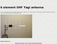 A standard 6 elements design scaled for UHF application. All material used in this project are easily obtainable tubes and rods which is limited within a total budget of $18.
 -
 Well documented Amateur Radio HF/VHF antenna projects, high power Russian GS35B RF amplifiers, mobile RFI solutions, related accessories, vintage radios, Six meter equipment, and useful techniques by K8CU are inside.
 -
 A 5-band (20m-10m) HF antenna - Just 7ft square and great for a small garden. Build it yourself for around 60 GBP.
 -
 The document discusses a two-element parasitic Delta-Loop array for the 40 meters band, aimed at radio amateurs interested in antenna projects. It provides detailed plans and instructions for building a homemade Delta-Loop antenna.
 -
 G8ODE antenna project, where the 40m & Short 80m antenna was deployed as a sloping wire antenna using the 10M fibre glass fishing pole and a hook on the house's gutter-board
 -
-
 A slightly different 6M antenna project by N1GY, an Off center fed antenna for the 50 MHz.
 -
-
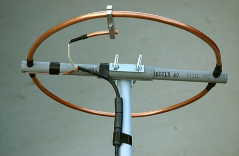
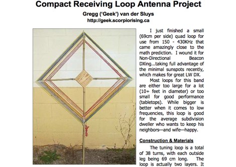 A receiving loop antenna project suitable for 150-430 KHz reception by Gregg van der Sluys
 -
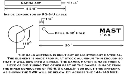
 2 Meter Halo Antenna project by Mike Fedler with many detailed pictues and detailes homebrewing instructions so you can build your own
 -
 An homebrew project for a 3 elements yagi monoband antenna for the 20 meters by 9M2MSO
 -
 The Windom antenna was widely used in the 1930s and is named after the amateur that wrote a comprehensive article about it
 -
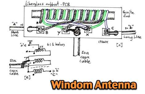 A windom multiband antenna project with pictures and diagram for the 6:1 balun
 -

-
 A homebrew project for a multiband end-fed antenna made with a single FT140-43 and 50pf capacitor and 20 meters of wire.
 -
 The 6 Band Inverted L Antenna MK3 is a versatile multiband antenna designed for amateur radio operators. This antenna covers 160m, 80m, 40m, 20m, 15m, and 10m bands, making it suitable for a wide range of HF communications. The design is based on a W3DZZ configuration, incorporating traps for optimal performance. The MK3 version features a sturdy 5/8th CB mast, replacing the original timber mast, which enhances durability against harsh weather conditions. The antenna's construction allows for effective operation, particularly on the 40m band, where it has been successfully used to contact distant locations including ZL, VK, and Antarctica. Constructing this antenna requires careful attention to detail, especially regarding the radials and grounding. The traps resonate at specific frequencies, and additional resources are available for building coaxial traps. The antenna is designed to work efficiently without an ATU on the lower bands, while higher bands may require tuning. This project is ideal for both beginner and intermediate operators looking to enhance their station with a reliable multiband antenna.
 -
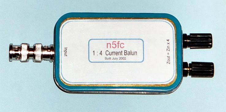 This project is intended to aid in tuning a balanced antenna or feedline that has a high impedance 100-600 ohms
 -
 Constructing a linear focus parabolic antenna for WiFi operation involves precise metalwork, as detailed in this project. The author, AB9IL, shares a build that can be completed in a few hours, emphasizing the hands-on process of shaping and assembling metal components. This design aims to provide enhanced signal range for 2.4 GHz wireless networks, a common challenge in many ham shacks and home setups. The project outlines the practical steps required, from initial measurements to the final assembly, including cutting, bending, and bolting various metal parts. While specific gain figures are not provided, the parabolic design inherently offers significant _directional gain_ compared to omnidirectional antennas, making it suitable for point-to-point links or extending network coverage over distances. The construction process focuses on readily available materials and basic shop tools, aligning with the DIY spirit prevalent in amateur radio. This antenna project is presented as a straightforward build, requiring attention to detail in fabrication to achieve optimal performance.
 -
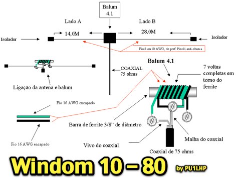 Project of a windom multiband antenna for 10 to 80 meters in portuguese
 -
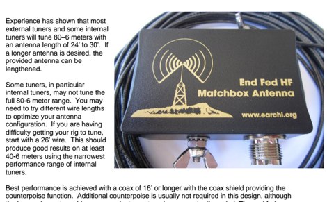 6m to 40m EndFed Half Wave Antenna project produces an inexpensive, multiband, end fed HF antenna matchbox that is quick and easy to setup and use.
 -
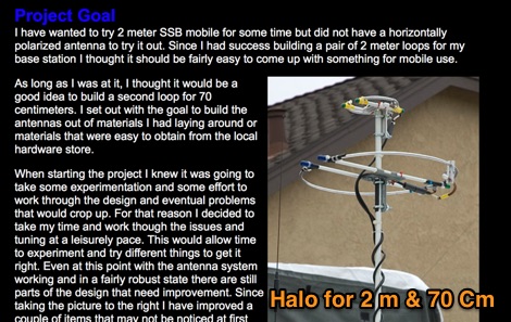 2 meter & 70 centimeter mobile halo antenna project, by N6TWW Mike Fedler
 -
 The article "Exploring the World of 10 Meter Beacons" by Ken Reitz, KS4ZR, provides an in-depth look at 10-meter beacon operations, focusing on their utility for propagation analysis. It details FCC Rules part 97.203 governing beacon stations, including license requirements, power limits (under 100 watts), and the specified band segment of 28.200-28.300 MHz for U.S. operations. The content highlights the diversity in beacon construction, from converted CB radios to home-brew QRP transmitters, and discusses the robust operating conditions these 24/7 stations endure. The resource presents several case studies of active 10-meter beacon operators like Ron Anderson KA0PSE/B, Domenic Bianco KC9GNK/B, and Bill Hays WJ5O/B, detailing their equipment, antenna setups, and typical signal report volumes. It also introduces the NCDXF/IARU International Beacon Project, which features 18 synchronized beacons worldwide transmitting on 28.200 MHz at varying power levels (100W, 10W, 1W, 100mW) to facilitate propagation testing. The article also covers the PropNet Project utilizing PSK31 on 28.131 MHz and the 250 Synchronized Propagation Beacon Project on 28.250 MHz. Practical advice for monitoring includes using the RST reporting method, understanding the impact of the solar cycle on 10-meter propagation, and tips for setting up a personal beacon, such as frequency selection and power output considerations. The IY4M Guglielmo Marconi Memorial Beacon Robot on 28.195 MHz is also mentioned for its automatic QSO mode. The article concludes with a list of other resources for 10-meter beacon information.
 -
 Yo5ofh j-pole antenna plans for 2 and 6 meters
 -
 An experimental fractal Quad antenna for 10 meter band project by AG1LE
 -
 A quarter-wave vertical antenna design for HF operation offers a practical solution for radio amateurs seeking a compact and efficient multi-band radiator. This project details the construction of a 5-band HF vertical, drawing inspiration from established commercial products such as the _DX COMMANDER_ and the MV6. The design emphasizes ease of assembly and disassembly, making it suitable for portable operations or installations with limited space. The article provides insights into various construction methods and offers practical tips for building a robust yet lightweight antenna. It highlights the benefits of a vertical configuration for DX contacts, particularly on the lower HF bands, and discusses real-world performance observations. The antenna is designed to cover multiple HF bands, providing versatility for various operating scenarios. Operators can achieve significant DX results with this type of antenna, often comparable to more complex arrays, especially when deployed with an effective ground system. The project aims to empower hams to build a capable antenna without significant financial outlay.
 -
 An Antenna Rotator Project. The rotor design is based on sandwiching the gears and gear supports between two 5/16 inch 6061 T-6 aluminum plates
 -
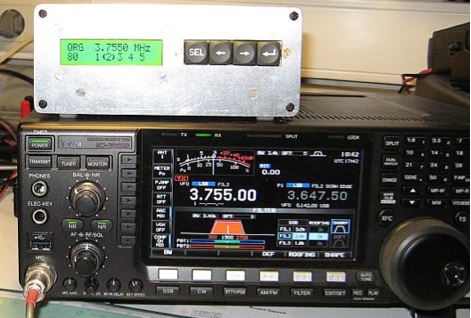 This Arduino project decode ICOM CAT frequency information and switch antennas according to preset values. RX and TX antennas can even be different, a project by ON7EQ
 -

-
 The page describes the construction of a simple omnidirectional, vertically-polarised dipole antenna for two metres using coaxial cable. It can be used indoors or outdoors, with no extravagant gain claims. The project is low-cost and can be completed in about 20 minutes.
 -
 Don't buy or build a semi-vertical trap antenna until you read this article! If you can use a drill, saw and screwdriver this is a simple project.
 -
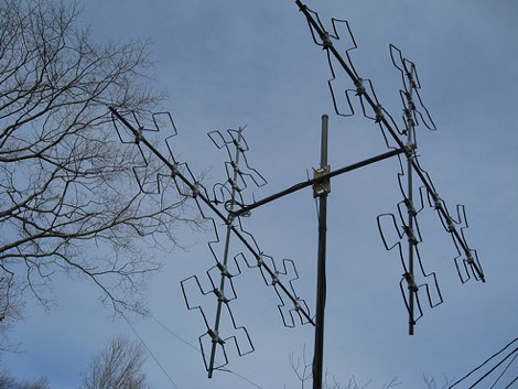
 A project for a portable antenna for amateur radio satellite reception, for 2 meters and 70 centimeters bands
 -
 Ham Radio Tower Project at N0HR. Includes site plan, escavation, tower construction, HF antennas, grounding and lightning protection, coax and more.
 -
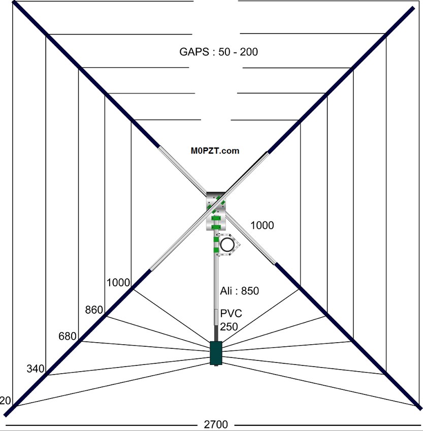
 JJ0DRC's HF multi-band delta loop antenna project, initially conceived during the waning peak of Cycle 23, addresses the common challenge of achieving effective DX operation from a small residential lot in Japan. Dissatisfied with a ground plane antenna's performance in SSB pile-ups, the author sought a beam-like solution without a tower, drawing inspiration from a JJ1VKL article in CQ Ham Radio Sep. 2000. The antenna, constructed in October 2000, employs two 7.2-meter fishing rods (37% carbon fiber, reinforced with cyano-acrylate glue and aluminum tape) and 1mm enameled wire, fed by an Icom AH-4 external antenna tuner. While the exact beam pattern remains unmeasured, JJ0DRC observed a significantly higher callback rate compared to dipole antennas, particularly on higher bands. The system's circumference length of 15-20m is crucial for maintaining a good beam pattern across HF bands, though performance on lower bands like 80m, 40m, and 30m becomes less directional as the length deviates from a full wavelength. Ongoing maintenance addressed degradation issues, including aluminum tape cracking and wire breakage at connection points due to strong winds (often exceeding 10-15m/s in winter). The author reinforced rod connections with IRECTOR PIPE SYSTEM components and INSU-ROCK ties, and improved wire attachment methods using Cremona rope and epoxy bond to enhance durability.
 -
 This resource details the computer-optimized design of the _ZS6BKW_ multiband dipole, an evolution of the classic _G5RV_ antenna. It begins by referencing the original 1958 RSGB Bulletin article by Louis Varney G5RV, explaining the operational principles of the G5RV's flat-top and open-wire feedline on 20m and 40m, noting its impedance transformation characteristics for valve amplifiers of that era. The article then transitions to the rationale for optimizing the design for contemporary solid-state transceivers requiring a 50 Ohm match. The core of the project involves using computer modeling to determine optimal lengths for the flat-top and matching section, aiming for a VSWR of less than 2:1 on multiple HF bands. It discusses the process of calculating feedpoint impedance based on antenna length and frequency, referencing professional literature from Professor R.W.P. King at Harvard University. The analysis also considers the characteristic impedance (Z(O)) of the open-wire line, identifying a broad peak of adequate values between 275 and 400 Ohms. Specific design parameters for the improved ZS6BKW are presented, including a shorter flat-top and a longer matching section compared to the original G5RV, with a velocity factor of 0.85 for the 300 Ohm tape. The article confirms acceptable matches on 7, 14, 18, 24, and 28 MHz bands when erected horizontally at 13m, and also discusses performance in an inverted-V configuration, noting frequency shifts. The author, Brian Austin ZS6BKW, emphasizes the antenna's suitability for modern 50 Ohm coaxial cable without a balun.
 -
 The I0JXX is an italian company that offers market their projects, also sells electronic products of high quality, both for Ham, both Broadcast and their accessories. VHF Antennas, mosfet power amplifiers, filters, insulators, power dividers, telescopic poles, antenna masts
 -
 A quarter wave vertical end-fed antenna for the 40 meters band. As all vertical antennas, also this aerial requires a good earthing system. In this project the ground is composed by twelve 4, wires buried in the lawn by using a spade to create a slit to drop the wire into.
 -
 Presents a comprehensive guide for constructing a broadband Hex Beam antenna, a popular directional array for HF operation. This design offers a compact footprint and excellent gain characteristics, making it suitable for limited space installations while providing significant performance advantages over omnidirectional antennas. The resource details the specific dimensions for a five-band Hex Beam covering 20, 17, 15, 12, 10, and 6 meters, emphasizing the critical element spacing and wire lengths required for proper resonance and pattern. It outlines the construction of the center post, spreaders, and wire elements, along with the feed point assembly, ensuring proper impedance matching. The project aims for a forward gain of approximately **5.5 dBi** on most bands, with a front-to-back ratio often exceeding _20 dB_. Building this antenna requires careful measurement and assembly, but the resulting performance provides a substantial upgrade for DXing and contesting.
 -
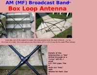
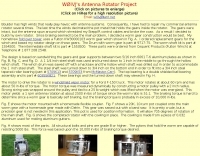
 The W1TAG LF Receiving Loop is a specialized antenna project for LF reception, designed to mitigate local noise and enhance weak signal pickup on the lower frequencies. This square loop, measuring 6 feet per side, utilizes 14 turns of #12 THHN wire wound on a PVC frame, offering a robust mechanical structure. The design incorporates a series-tuned circuit with a coupling transformer, allowing for tuning from over 400 kHz down to _45 kHz_ using a switched capacitor bank. Construction details include the use of 1.5-inch PVC pipe for the frame, with specific measurements for spreaders and drilled holes for wire threading. The two 7-turn sections of wire are connected at the center, providing an option for a center tap. The loop rotates on a 1-inch steel pipe, enabling directional nulling of noise sources. The tuning unit, housed in a box clamped to the PVC, employs a 1:2 step-up transformer wound on an _FT-82-77 core_ and uses relays to switch capacitance values from 50 pF to 6400 pF, providing precise frequency adjustment. The current setup connects to the shack via 100 feet of RG-58, feeding into a W1VD-designed preamp, with plans for a balanced, shielded twisted pair cable upgrade.
 -
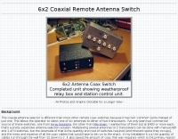 6x2 coaxial remote antenna switch, completed unit showing weatherproof relay box and station control unit.
 -
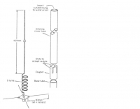
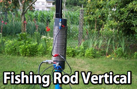 A homebrew fishing-rod vertical using a very nice design from EB5EKT. This antenna works 20, 30, and 40M bands by selecting the tap points using alligator clips
 -
 A 2.4 GHz WiFi antenna that can boost your WiFi signals for many miles. It\'s an easy to build Yagi antenna project done with some popsicle sticks, paper clips and glue.
 -
-
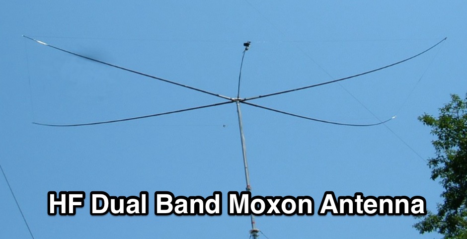
 A Mini Moxon antenna for 40 meters band project in a well done PDF document
 -
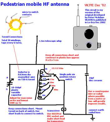 This antenna allow transmission and reception on all bands between 7Mhz and 28 Mhz. Similar in concept to the Miracle Whip by VK3YE
 -
 This project outlines the construction of a 3-element reversible quad antenna specifically designed for the 40-meter band. The materials required include pushup towers, pressure-treated posts, insulated wire, and various electrical components such as relays and a balun. The construction process is straightforward, beginning with the installation of the posts in a straight line, followed by the assembly of the antenna elements and their elevation to the desired height. The antenna's design allows for directional signal reception, making it ideal for operators looking to enhance their communication capabilities on the 40-meter band. The project includes detailed instructions on tuning the antenna for optimal performance, ensuring that operators can achieve the lowest SWR possible. Additionally, the design can be adapted for other bands by extrapolating dimensions, providing versatility for amateur radio enthusiasts. Overall, this reversible quad antenna project is suitable for both beginners and experienced operators, offering a practical solution for improving signal strength and directionality in 40-meter communications.
 -
 A schematic design of the W3DZZ antenna in portugues with description of trap building
 -
 This resource details the construction of a versatile CW/QRSS beacon, designed around a Microchip _PIC16F84_ microcontroller. The project provides a flexible platform for transmitting either standard CW or very slow QRSS signals, making it suitable for LF, VHF, UHF, and SHF applications. It supports two distinct messages, each configurable for speed (from 0 to **127** WPM for CW, or up to **127** seconds per dot for QRSS) and repetition within a six-phase sequence. The core functionality relies on the PIC's EEPROM, which stores all operational parameters, including message content, transmission speeds, phase configurations, and relay control settings. This design allows for parameter modification directly via programming software like _ICProg_ without altering the main program code. The project includes a detailed schematic, a component list, and an explanation of the EEPROM memory mapping for messages, speeds, phase settings, and inter-phase delays. General-purpose outputs (OUT1, OUT2, OUT3) provide dry relay contacts for external control, enabling functions such as power switching, antenna selection, or frequency changes. A 'TRIGGER' input facilitates controlled starts or continuous free-run operation. Sample EEPROM configurations illustrate how to program specific beacon sequences, including message content and relay states.
 -
 YF1AR 80 to 40 meter vertical antenna project